Project 1
Assembly Preparation
- Define the mechanical components electrically and prepare the catalogue for the same
- Create new product file and name it Main Context Assembly.
- Create new product inside main assembly and name it Wiring Harness Assembly.
- Add Engine Lite file and L clip for interconnection connector in main context assembly.
- In Wiring harness assembly add required connector, P clamp, Furr Tree clamp by defining each electrically.
- Open channel bottom and save as channel_bottom _right.
- Modify new created channel according to position of injector pins location.
- Create curve/straight line in channel for bundle.
- Define both right and left side channel electrically.
- Place all connector at proper place using smart move and manipulation tool.
- Place P clamp and furr tree at tentative location.
- Place channel at proper location.
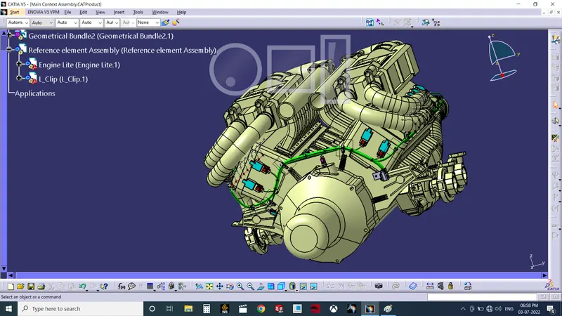
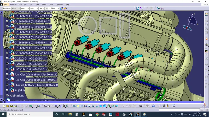
Routing
- Activate Wiring harness Assembly.
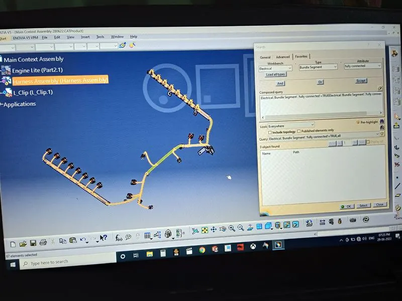
- Click Geometrical bundle and select assembly.
- Using multibranchable, start routing from main connector.
- Enter required diameter, slack, start point, end point, tangent direction and complete routing.
- Using add branch point create branch point at desire location.
- In channel use curve for routing purpose.
- Check continuity of bundle.
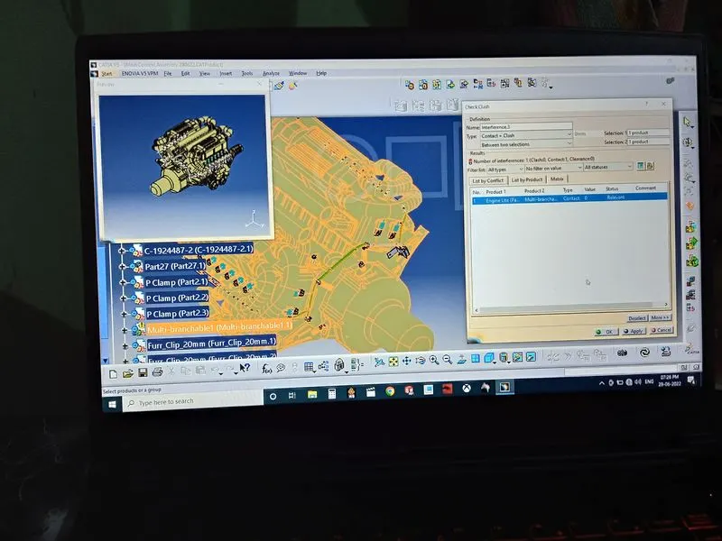
- Check clash/contact between engine and multibranchable and adjust slack accordingly.
- Save main context assembly.
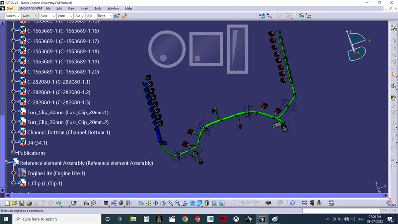
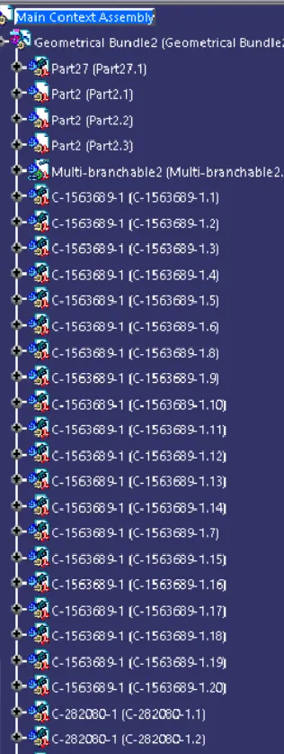
Flattening
- Activate Wiring harness Assembly.
- Create new Cat Product File and name it flattening assembly save in same location.
- Switch to electrical harness flattening environment.
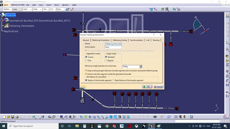
- Using Harness Flattening Parameter select plane, keep tangent option.
- In drawing tab select for bundle segment single and for protective covering double line so that bundles with protective coverings show different visual in drawing view.
- Graphic representation select 3D.
- Save the parameters.
- In window tile horizontally both product file.
- Select extract option and select require assembly to flatten.
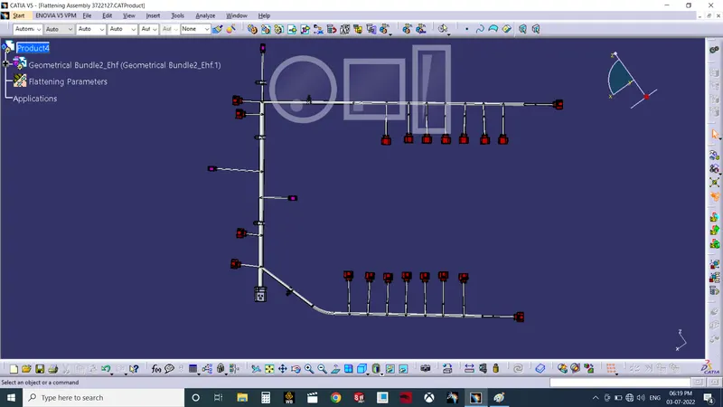
- Select flatten command and select appropriate plane.
- According to requirement use Rotate, bend, roll command.
- Save the file.
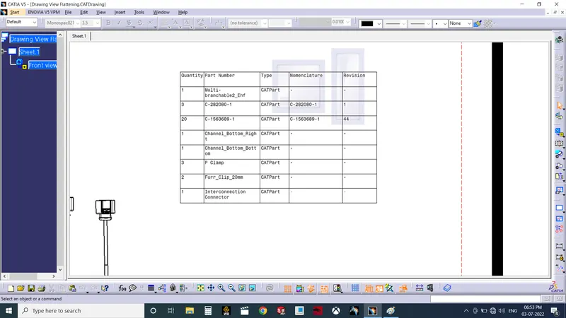
Preparation of Drawing sheet and BOM
- Activate Wiring harness Assembly.
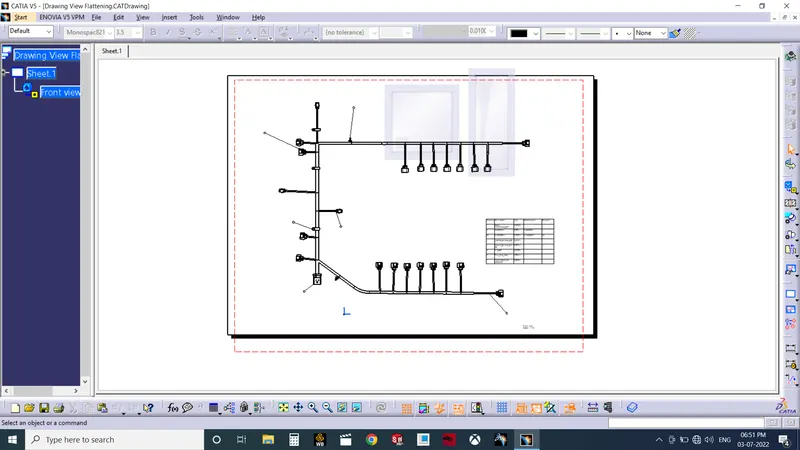
- Create new drawing file and select required drawing sheet size and orientation.
- In properties 3D wireframe select always visible option.
- Tile both product files vertically.
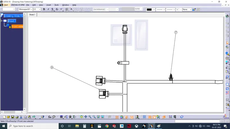
- Select Front view and select connector face.
- Using manipulation tool orient in required direction.
- In properties select wireframe always visible.
- Save File.