Project 1
AIM:
- To route the wiring harness on given engine and flatten view drawing in CATIA V5.
INDROUCTION:
- Wiring harness forms the backbone of the electrical architecture in any vehicle electrical system design.Wire harness is the interconnecting wiring in the vehicle for the transmitting electrical power and signals in the electical system.The increase in the electrical and electronic content in the automobiles has resulted in the wire harness design becoming more and more complex.From the simple function of electrical power distribution and transmitting signals,it has become a networking of multiple controllers with a vast range of sensors,actuators and their interfaces.Many CAD tools and design software have evolved to virtually develop the harness.
- An Engine wiring harness is a an organized set of wires,cables,connectors and terminals that control a vehicle's electrical system.Engine wire harnesses relay electical power and control information to outlaying components such as;
- Alternators
- Audio systems
- Batteries
- Blower motors
- computers
- Fuel Injectors
- Fuses
- Windshield Wipers
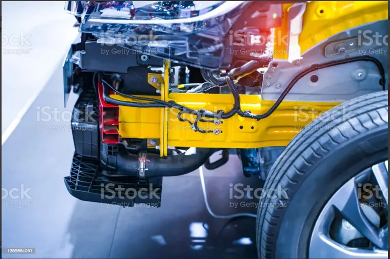
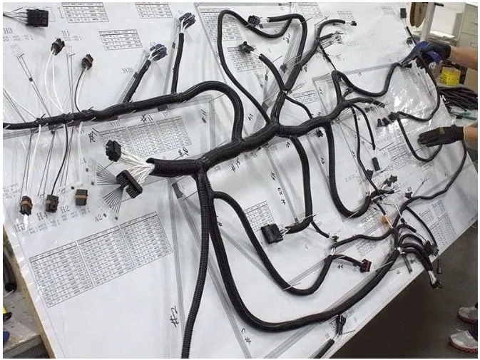
Imges below shows typical wiring harness system designed for vehicle
ENGINE HARNESS DESIGN CRITERIA AND PACKAGING RULES
- Wiring harness should be routed in such a way that it is easy to assemble on vehicle .Wiring harness topology plays important role to meet this criteria.
- Wiring harness should be routed in such a way that it is easy to access in case of service or failure analysis.
- Wiring harness roting shall provides easy in manufacturing,accessibility,easy removal and easy maintenance of attached equipments and wiring harness.
- Routing through small structural holes and openings shall be avoided to minimize chaffing and handling of the wiring harness during installation.
- Provided additional slack to the harness according to the surrounding and harness bending requirements.
- Ensure that worst case envelope dimension are considered for dynamic assemblies to meet the desired clearance requirements with wiring harness bundles.
- Avoid routing over the bolts,near the bolted joints or screwed joints.It may damage harness or may puncture the harness.
- Avoid the harness routing near the sharp edges or over the sharp edges like thin sheet metal brackets,panel joints.
- Ensure that harness is routed at least 100 mm away from ABC pedals,clutch lever and cables,engine timing belt or any other dynamic components.
- Enough clamps shall be provided to ensure the positive clearance with surrounding and saftey of wiring harness.Distance between two clamps on a straight branch should be maximum 200mm.
- If the harness is routed between dynamic and stationary assemblies,then ensure that fixed positive clamping is provided immediately at the both end of assemblies.This is required to avoid harness damage in rocking conditions.
- Harness should be kept away from engine lifing hooks.
- Use of rubber grommets is recommended if harness is passing through sheet metal panels.Rubber grommets must be used if harness is subjected to vibrations or mechanical fatigue loads/movements.Rubber grommets must eb used if harness is passing through wet zone of the vehicle .
- Telescopic grommets are recommended to use for harness passing through closures .
Ensure that harness branching is in line following requirements.
- Branch length should be minimum 50 mm.
- Minimum distance between clip and nearest branching point should be 25mm.
- Minimum distance betwwen two breakouts should be 50 mm.
- Limit the number of branches from single branching point to 4.
- Ensure that harness protection is provided according to surrounding temperature,manufacturability and expected reliability.
ENGINE HARNESS DESIGN PROCEDURE
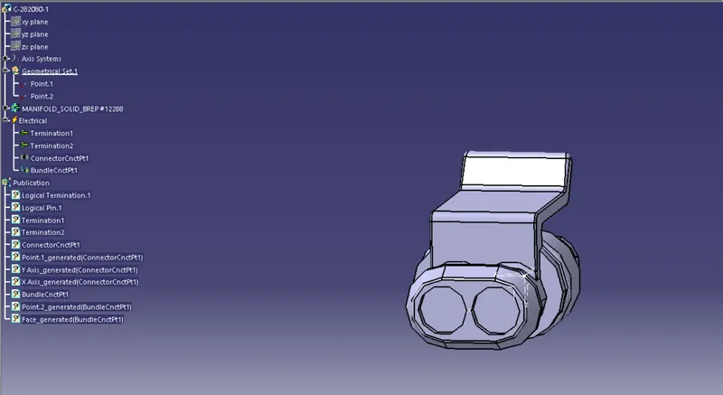
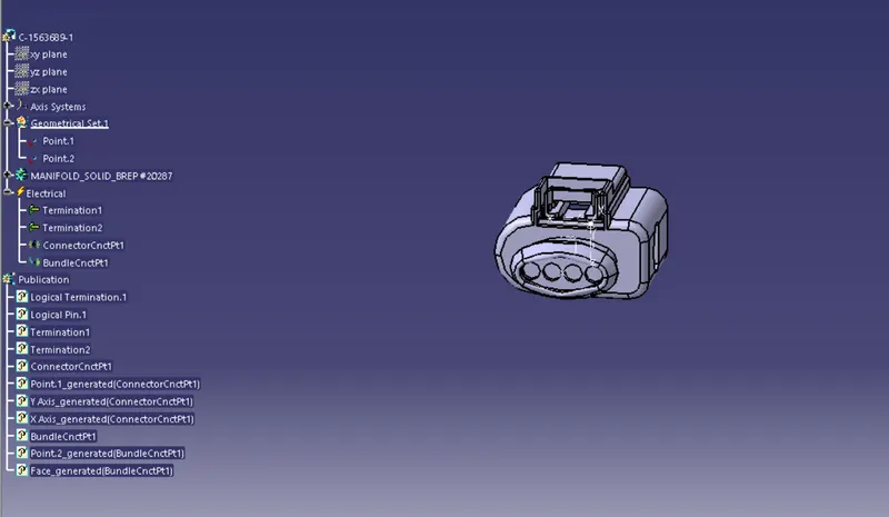
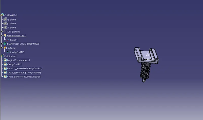
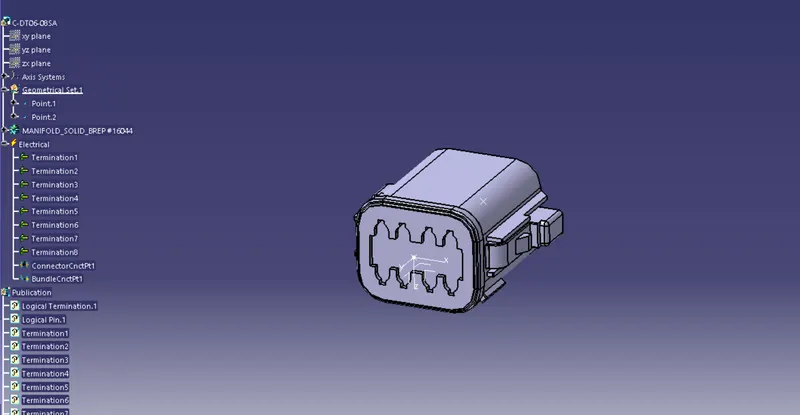
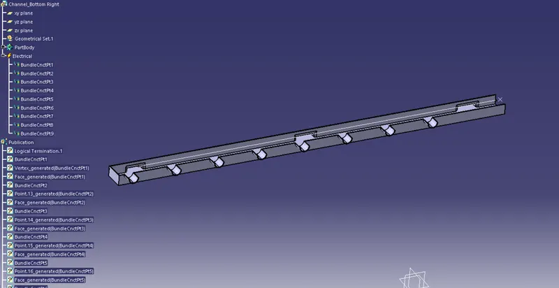
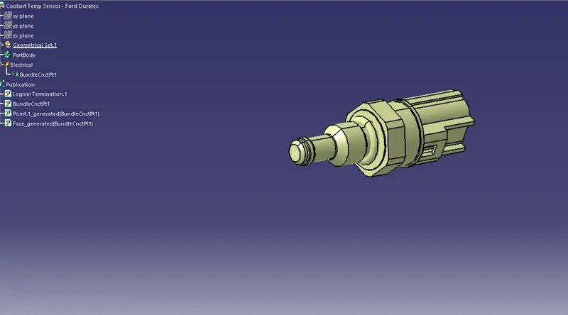
Define all the connectors,clippings and clamping.Image below shows the connectors,clips and clamps used in the harness routing.
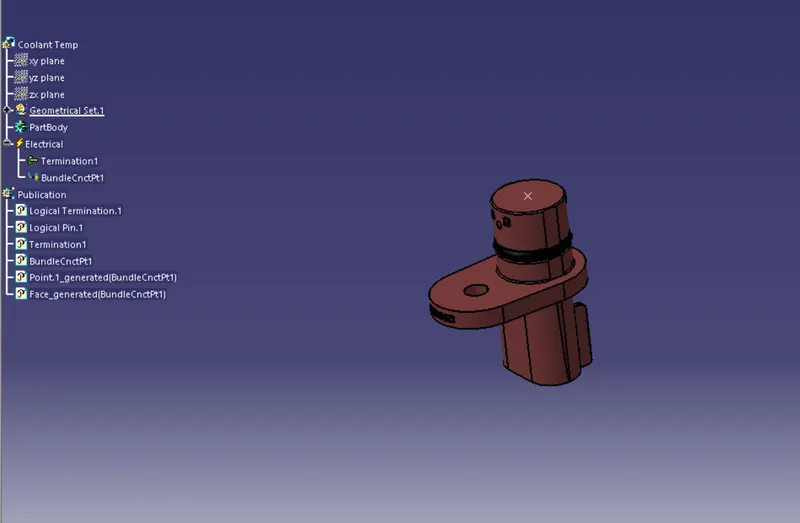
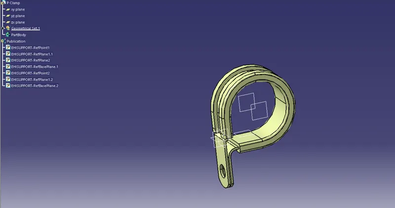
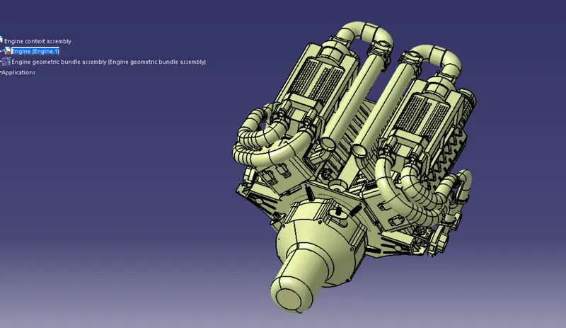
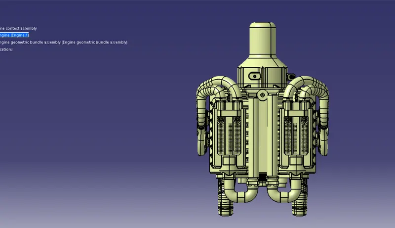
STEP 1: CHECK FOR ALL THE CONNECTORS POSITIONS,CLIPPING AND CLAMPING POSITIONS IN THE GIVEN ENGINE DATA.
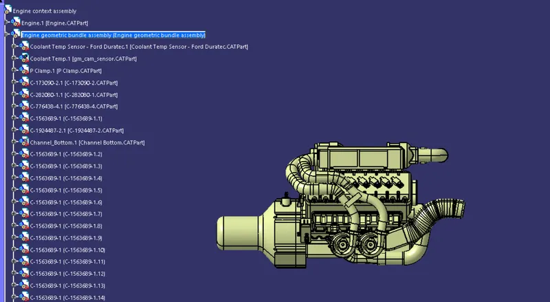
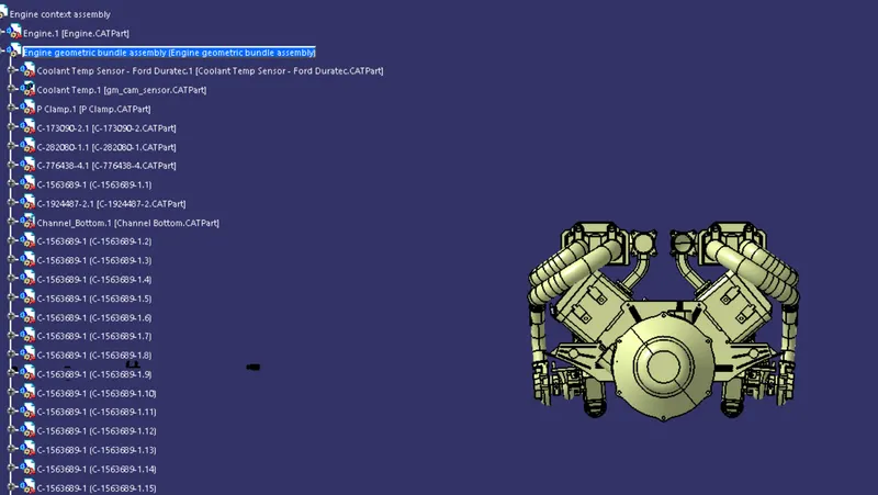
STEP 2: CREATING CONTEXT ASSEMBLY:
- A context assembly has to be created which will serve as the main assembly for engine harness.The context assembly will contain the 3d-CAD data V16 engine harness geometrical bundle.If any sheet metal brackets are required then they added in this "ASSY ENGINE HARNESS CONTEXT".
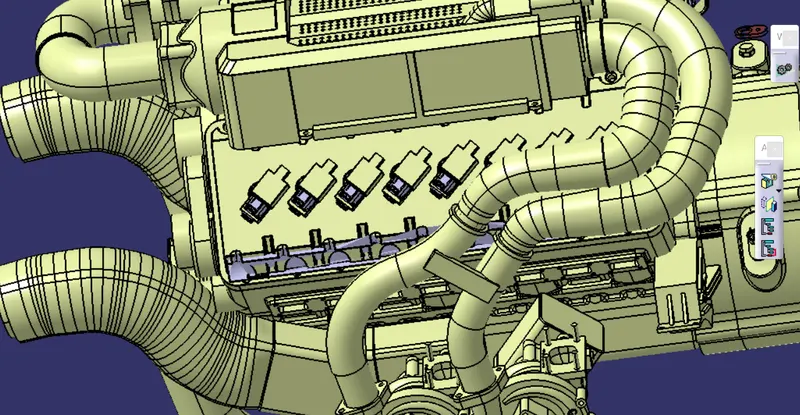
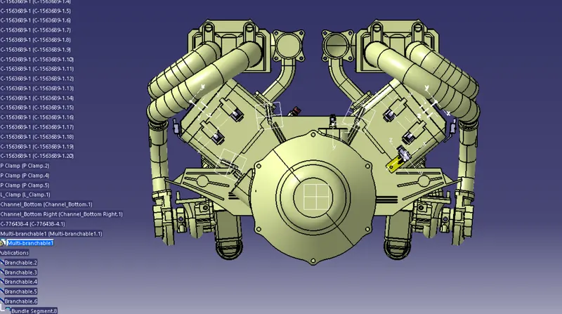
STEP 3: ADDING CONNECTORS TO ALL 16 FUEL INJECTORS SENSORS AND 4 CAM-SHAFT SENSORS:
- In this step,we are placing connectors to fuel injectors sensors and cam-shaft sensors.So we will require total 20 connectors which have to be added in the engine harness geometrical bundle assembly.We have to use manipulation tools along with compass,snap and smart move feature to locate all the 20 connectors at their desired locations.
STEP 4: ADDING SHEEET METAL BRACKET & MOUNTING THE INTERCONNECTION CONNECTOR ON THE SHEET METAL BRACKET AND MOUNTING THE P CLAMPS FOR WIRE HARNESS
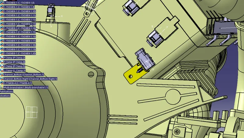
- Now,we have to add sheet metal bracket in order to provide mounting for the interconnection connector.Also,we have to make sure that the bracket is placed inside the context assembly and outside of engine and geometrical bundle assembly.
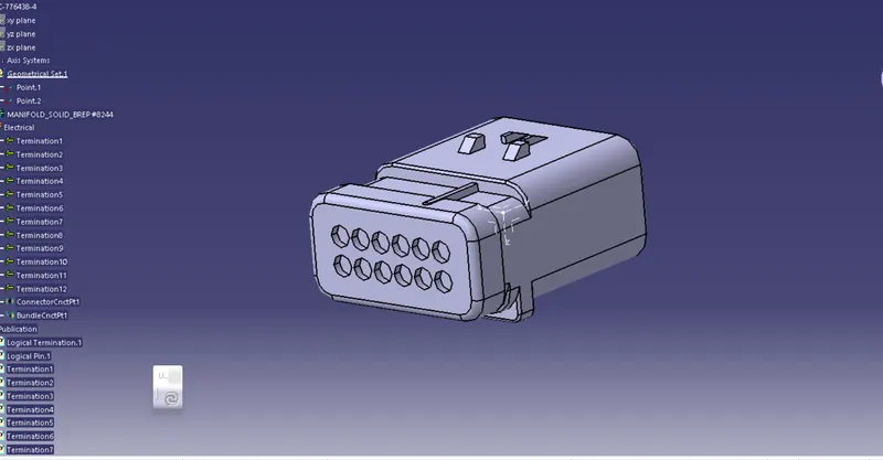
- Here the 12 pole connector "c-776438-4" and the mounting cavity "c-1924487-2" is together used as interconnection connector.The required data is downloaded from te.com.First,we have to define 12 pole connector and mounting cavity electrically as above the image.
- A mounting cavity "c-1924487-2" is electrically defined as show in above figure.
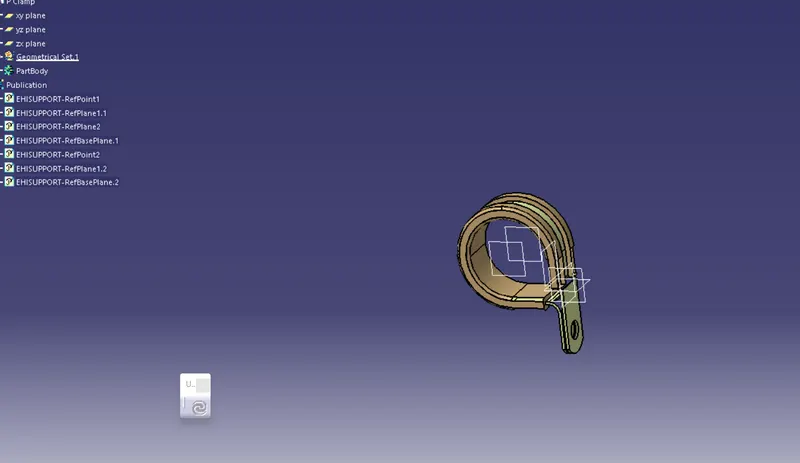
- We have to mount 3p-clamps and before that we have to define p-clamp electrically with geometrical parameters,entry and exit point on both left and right side of the p-clamp as show in below image.
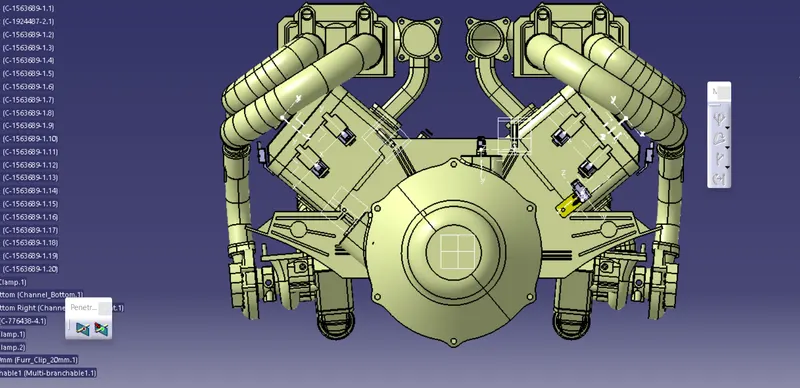
STEP 5: MOUNTING OF PLASTIC GUIDING CHANNEL:
- We have to add now plastic guiding channel because V16 engine has 8 injectors on right side and 8 injectors on left side which are very close to each other.Hence plastic guiding channel is best option for proper and easy routing of the wiring harness.It will reduce the complex wiring harness routing.We will now,before placing guiding channel,we have to define geometrical parameters of guiding channel as below.
- In above figure,we have created point 1 at entry face and another point at endpoint at 560mm distance.
- Now,join that both points and create a line which will be later used for routing the wire harness bundle inside the guiding channel.
- Above figure shows for the left side guiding channel and same process will be repeated for the right side channel.
- We have created bundle entry points for the eight connectors, one bundle entry point at channel entry face defined guiding channel electrically as equipment.
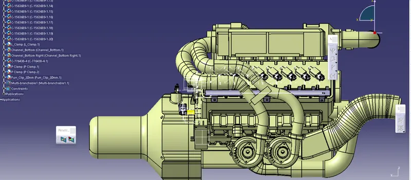
- After electrically define of guiding channel,we have located guiding channel at desired place as show in above figure.
- Here we have used different coomands like manipulation,snap,smart move, compass etc.for placing of guiding channel.
- Now at this stage ,we have just located bottom of the guiding channel.
- All 20 connectors ,3p-clamps, 1 interconnection,1 furr tree clips and 2 plastic guiding channels are mounted.
STEP 6: BUNDLE ROUTING FROM INTERCONNECTION CONNECTOR TO 3P-CLAMPS:
- Here,we are routing the bundle segment from interconnection connector to 3 p-clamps .The diameter for this routing path is 15mm and bend radius ratio is assumed to be 1.4.
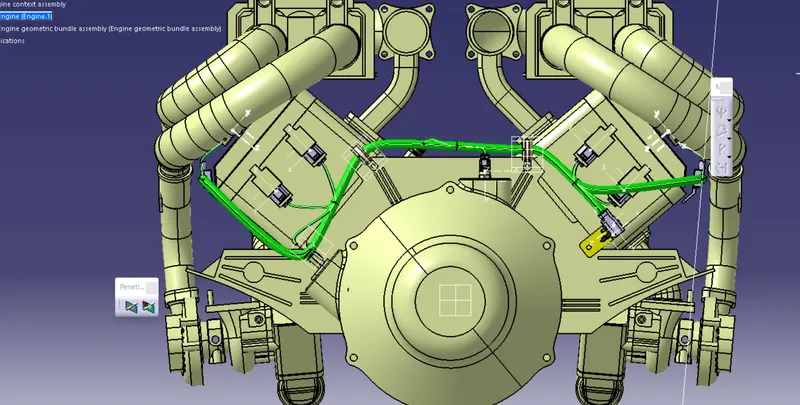
- Adding branch point to the bundle segment at distance of 55mm from p-clamp as show in below figure.
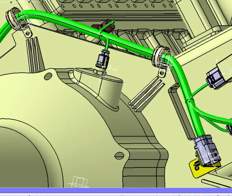
STEP 7: ADDING BRANCH POINTS TO BUNDLE SEGMENT INSIDE THE GUIDING CHANNEL:
Here,from entry side of the guiding channel,we have created first branch point at 130mm and then subsequently created six branch at 65mm.
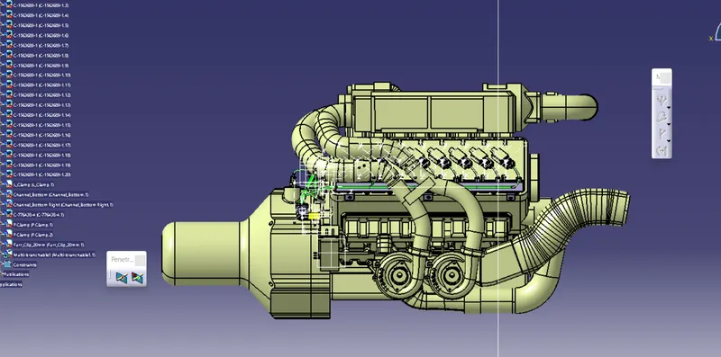
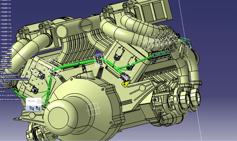
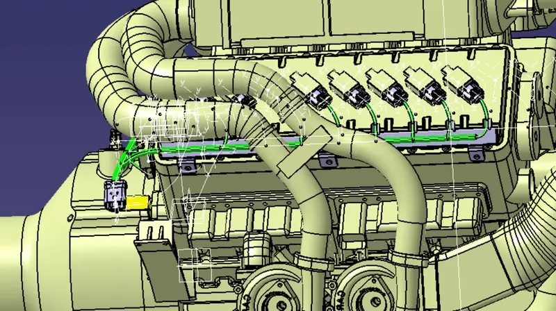
- In above the figure,we are routed bundle segment from the newly created branch points to the 8 fuel-injectors connectors.The bundle diameter is assumed to be 5mm.
- Similarly,we have done routing for the left side guiding channel.
STEP 8: ADDING PROTECTIVE COVERINGS AND GUIDING CHANNELS TOP SHELL TO HARNESS BUNDLE:
Here in below figure,we have done with whole wiring harness routing for the engine.Now,we have to add protective coverings to all bundle segments and top shell of the guiding channel.
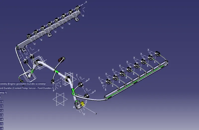
- In above figure,we have added 15mm slit cot tubes on top of the bundle segments as a protective covering.We have asssumed start and end extremity for the COT tubes approxmimately.
- we have added 7mm cotton tape on all the bundle segments connecting to the all 20 connectors.
- We have added all the slit cot tubes and cotton tapes on bundle segments as a protective coverings.Also,we have added top of the both left and right side plastic guiding channel.
STEP 9: CHECKING BUNDLE CONTINUITY:
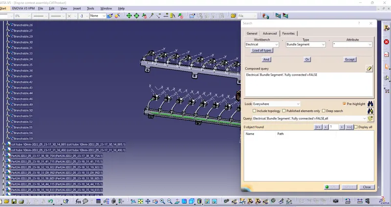
- In this step,first we have to make sure that multi-branchable is selected then we have to go in Edit>Search>Advanced>Workbench-Electrical>Type-Bundle segments>Attribute-Fully connected.
- By selecting 'True option will show all the connected bundle segments while selecting'False'option will show all the non-connected bundle segments.
- Here,we have selected for the 'True' option and searched for results.All the bundle segments are highlighted found showing that all the bundle segments are electrically connected as show in below figure.
STEP 10: CREATING FLATTEN VIEW OF THE ENGINE HARNESS GEOMETRICAL BUNDLE ASSEMBLY:
- In this step,For creating flatten view we have to work in electrical harness flattening workbench of Catia V5.We should also make sure that the flattening file saved in the same folder where other files of harness assembly are saved.
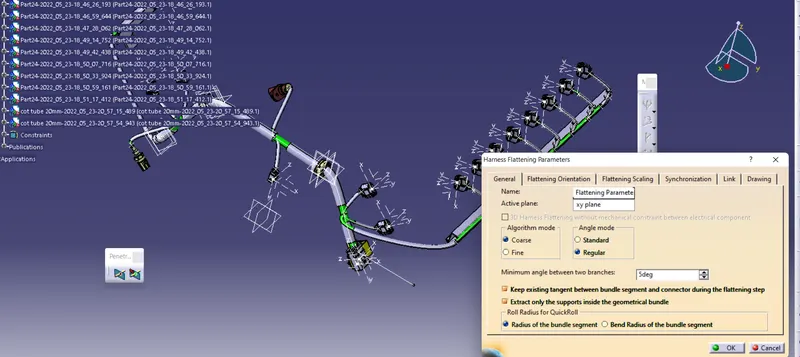
- Before creating flatten view,first we have to define flattening parameters.Make sure that selecting 'Single line " for bundle segment and 'Double line' for protective covering.
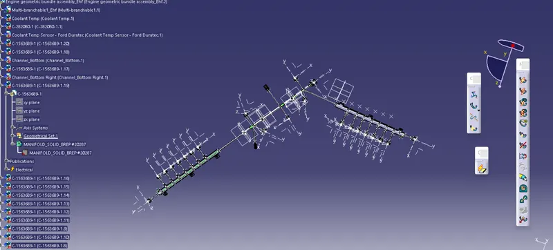
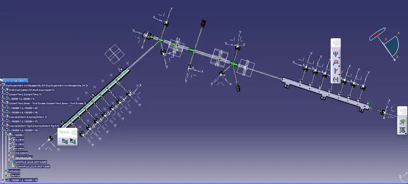
- We have extracted the bundle assembly into engine harness flattening product file and then flattened the file along face of interconnection connector as show in above figure.
- At this stage,for clarity,we have been hidden the flattening diagram of the plastic guiding channels from the drawing view.
STEP 11: CREATING A FLATTEN VIEW DRAWING FOR THE WIRING ASSEMBLY:
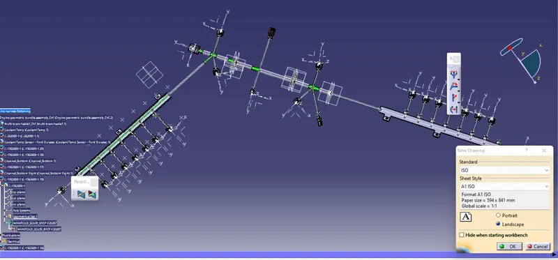
- In above figure created.we are creating new drawing file and defined all the necessary drawing parameters.We have to insert the front view of the engine harness flattening product file into the drawing file
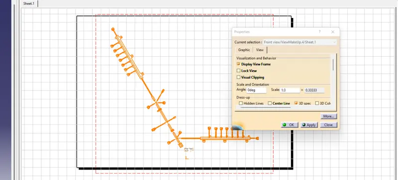
- We have to define drawing properties as shown in above figure.It should be noted that in 'Dress up' setting 3d wireframe is always On.If this setting is not selected then the bundle segments won't be visible on drawing view.
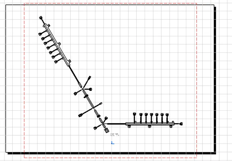
- Above figure shows,the final drawing view of the engine harness flatten view.
CONCLUSION
In this way,we have routed wiring harness for the V16 Engine.Also,prepared flatten view drawing with proper sheet in CATIA V5.