Project 1
AIM AND INTRODUCTION:
* To calculate the dead load , IRS live loads , Earth pressure load , wind load and seismic loads for the bridge structure at Ahmedabad Metro rail project shown in the figure. Assume the unit weight of soil as 18 kN/m3 . Use IS 875 code book for finding the Basic wind speed at the site location. Use IS 1893 code book for determining the seismic zone. Assume suitable data.
*Model the bridge structure in Staad Pro and Apply all the calculated loads.
PROCEDURE:
To calculate wind pressure;
Wind Speed=Vz=Vb*K1*K2*K3*K4
Basic Wind Speed,Vb=39m/s(From IS 875 PART III 2015)for the region in Ahmedabad.
- FACTOR K1;
Referring Table 1 of IS 875 PART III 2015, For important structure and wind speed 44m/s, the K1=1.06.
- FACTOR K2;
Referring Table 2 of IS 875 PART III 2015, For height less than 1.5m and category 1 structure K2=1.12.
- FACTOR K3;
As per Cl 6.3.3 IS 875 PART III 2015 for upward wind slope less than 3 Degree Factor, K3=1.00.
- FACTOR K4;
When the location is not within 60KM radius of the ocean, the cyclone factor is taken in to account K4=1.0
DESIGN WIND SPEED Vz=Vb*K1*K2*K3*K4
=39*1.06*1.12*1.00*1.0
=46.3008m/s
WIND PRESSURE=0.6*Vz^2
=0.6*(46.3008)^2
WIND PRESSURE =1.286.25KN/m^2.
Since the Staad file is mentioned in the above problem we are going to apply the dead load,IRS live loads,Earth pressure load,wind load and seismic loads for the bridge structure.
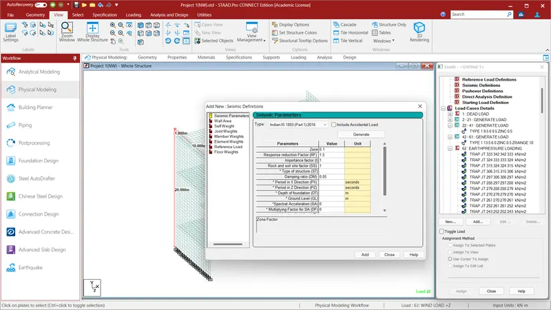
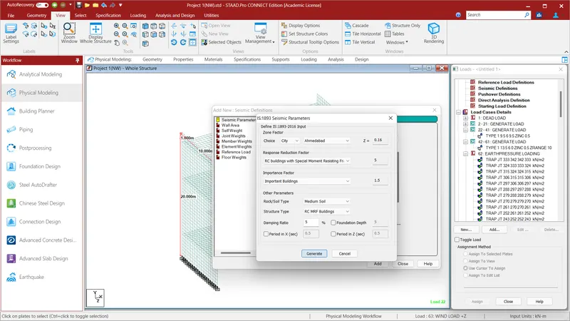
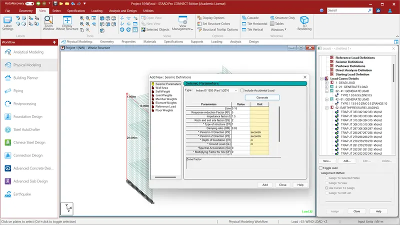
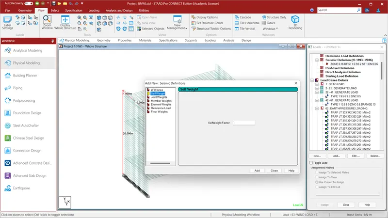
We have to assign the seismic definitions and the load case in order to to run the Staad file. To do so go to the Loading menu and select Definitions and click Seismic Definitions . In Seismic Parameters select the Type as Indain IS 1893(Part I)2016 and click Generate. Since the given project is located at Ahmedabad given in the above problem select the City as Ahmedabad where the assigned zone factor for the city is Z=0.16.Give the Response Reduction Factor as RC Buildings with Special Moment Resisting Force as 5. For Importance Factor select the Important Building in which the Factor is 1.5. Give the Rock/Soil Type as Medium Soil and Structure Type as RC MRF Buildings.Give Damping Ratio as 5 and click GENERATE and click ADD. Then select the Seismic Zone and select the Self Weight and give the SelfWeight Factor as 1 and ADD.
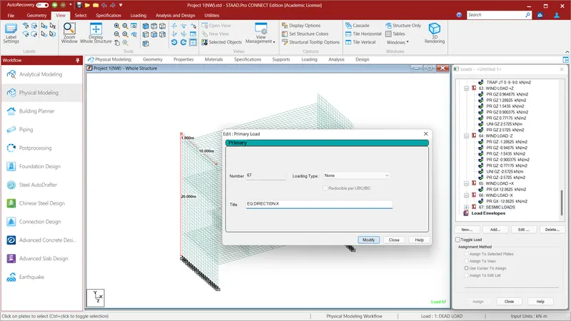
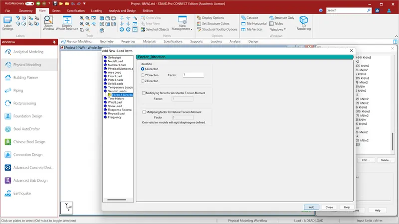
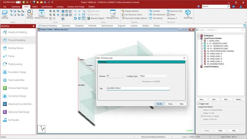
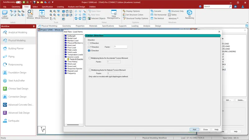
Go to the Load Case Details and give the name EQ DIRECTION X and click ADD. Select the EQ DIRECTION X and click ADD Load Beams column will appear . In that select Seismic Loads and in Factor & Direction give the Direction as X and factor as 1 and click ADD. Again go to the Load Case Details and give the name EQ DIRECTION Z and click ADD. Select the EQ DIRECTION Z and click ADD Load Beams column will appear . In that select Seismic Loads and in Factor & Direction give the Direction as X and factor as 1 and click ADD. For the given Staad File we have assigned the Seismic Loads. Now we shall assign the Dead Loads to the Staad File.
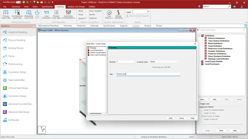
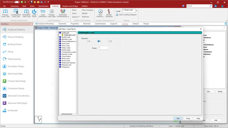
Select the Load Case Details and give the Title as Dead Load and click ADD. Again select the Dead Load and click Add . In that select the SelfWeight Load in Self Weight and give the Direction as Y and Factor as -1 because selfweight always acts vertical direction and in the opposite to the structure. Now go to Select option and select the Geometry node and select all the structure and select Assign to Selected Beams/Plates and clcik Assign and click YES. Self Weight to the whole structure i.e., Dead Load is applied. We have assigned the Seismic Load and Dead Load to the given model. Now we shall assign the Metro Live Load to the given Staad File.
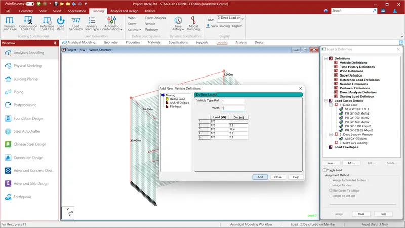
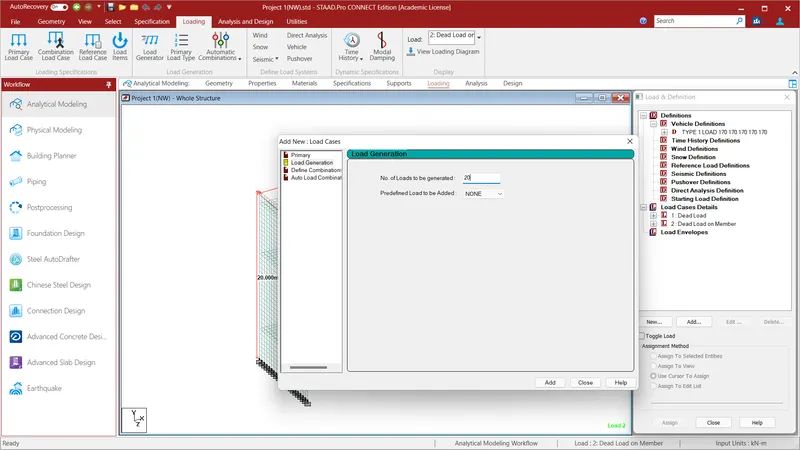
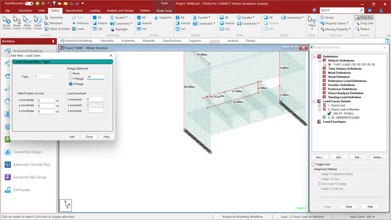
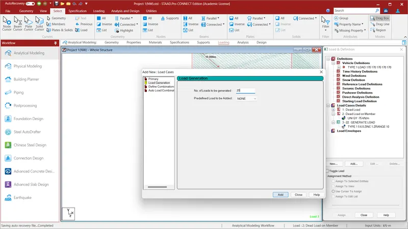
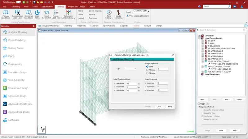
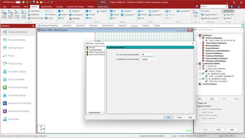
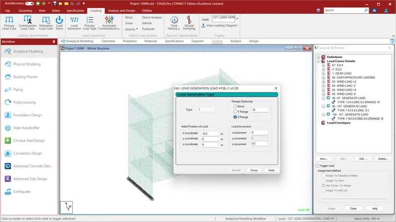
Since it is 3 Lane Metro Track we have to apply the Live Load to all the three tracks. To do so go to Definitions option and select Vehicle Definitions and Define the Load . Assign the following Values Vehicle Type Ref as 1 and Width as 1.Mention the Load in KN and Dist in m. followed by the values 170KN load the distance is 2.2m. For 170KN load the distance is 12.4m .170KN load the distance is 2.2m and click ADD. Now go to the Load Case Details and select the Load Generation . In that give No.of Loads to be Generated=20 and Predefined Load to be Added as None and click ADD. Go to select option and select the node cursor and select the node on the 1st track and define the coordinates as X Coordinate=5;Y Coordinate=6;Z coordinate=0 and give the range as Z=10. The Load Increment is 0.5 and click ADD.Again go to the Load Case Details and select the Load Generation . In that give No.of Loads to be Generated=20 and Predefined Load to be Added as None and click ADD. Go to select option and select the node cursor and select the node on the 2nd track and define the coordinates as X Coordinate=9.5;Y Coordinate=6;Z coordinate=9.5 and give the range as None. The Load Increment is -0.5 and click ADD. Again go to the Load Case Details and select the Load Generation . In that give No.of Loads to be Generated=20 and Predefined Load to be Added as None and click ADD. Go to select option and select the node cursor and select the node on the 3rd track and define the coordinates as X Coordinate=16.5;Y Coordinate=6;Z coordinate=0 and give the range as Z=10. The Load Increment is 0.5 and click ADD. Now all the Load cases are applied . We shall have completed IRS Live Loads.
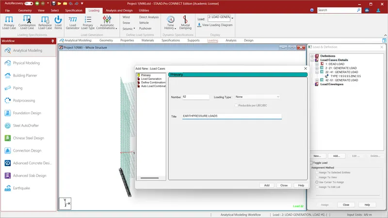
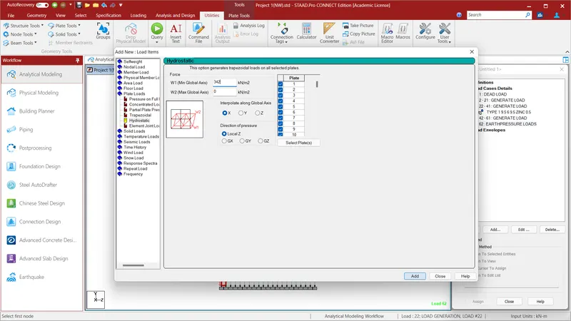
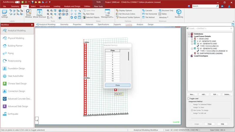
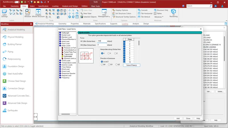
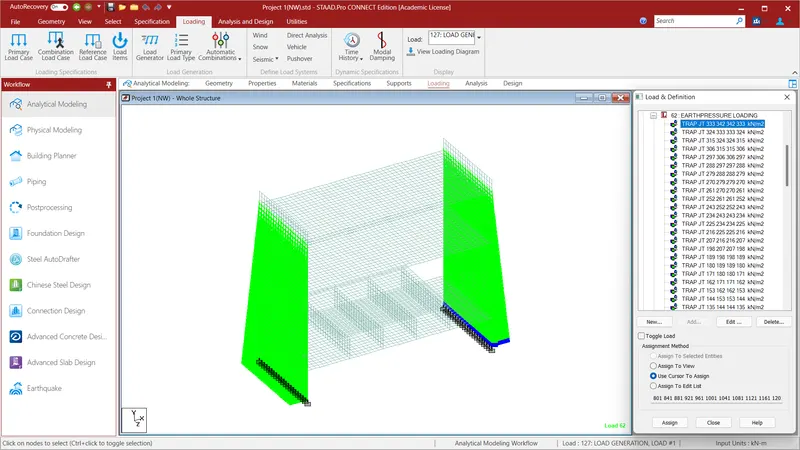
Now we will apply the Earth Pressure Load to the given Structure. To do that go to Load Case Details and give the title as EARTH PRESSURE LOADS and click ADD. Go to the EARTH PRESUURE LOADS and click Add and select the Plate Load. In the Plate Load select the Hydrostatic Load and give the Force W1(Min.Global Axis)=342KN/m^2.{In the given problem the Unit Weight of Soil is 18KN/m^3 and load acting on the wall is upto 19m i.e., 18*19=342KN/m^2} and W2(Max.Global Axis)=0KN/m^2. After assigning the loads we have to select the plates to apply the given loads . To do so select the Select Plate(s) option and select the 1 vertical column plates upto 19m from the fixed support and click Add. Go the Direction of Pressure as Local Z and Interpolate in the x Direction and click Add. We shall have assigned loads to the sinle vertical plates . To assign to all the plates go to the view option and select the side view option and select each horizontal plates and click Assign to Selected Plates and click assign and click YES. We shall have assinged loads to all the vertical plates upto 19m from the fixed supports.Again go to the EARTH PRESUURE LOADS and click Add and select the Plate Load. In the Plate Load select the Hydrostatic Load and give the Force W1(Min.Global Axis)=-342KN//m^2.{In the given problem the Unit Weight of Soil is 18KN/m^3 and load acting on the wall is upto 19m i.e., 18*19=342KN/m^2} and W2(Max.Global Axis)=0KN/m^2. After assigning the loads we have to select the plates to apply the given loads . To do so select the Select Plate(s) option and select the 1 vertical column plates upto 19m from the fixed support and click Add. Go the Direction of Pressure as Local Z and Interpolate in the x Direction and click Add. We shall have assigned loads to the sinle vertical plates . To assign to all the plates go to the view option and select the side view option and select each horizontal plates and click Assign to Selected Plates and click assign and click YES. We shall have assinged loads to all the vertical plates upto 19m from the fixed supports.We would have applied the Dead Loads, IRS Live Loads, Earth pressure loads and Seismic Loads to the given Staad File. Now the remaining load to be applied is the Wind load.
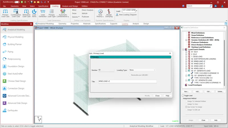
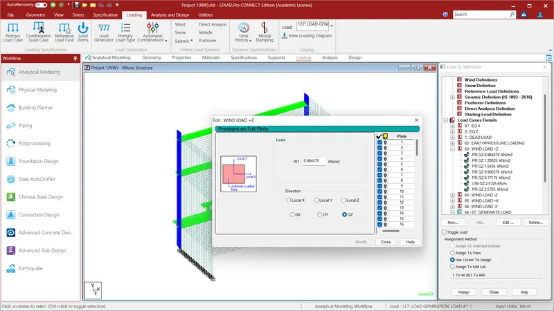
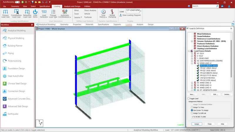
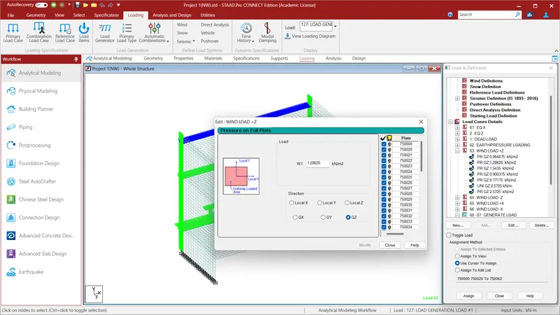
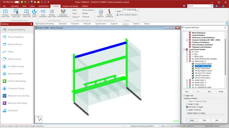
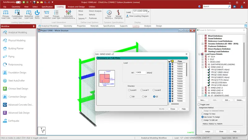
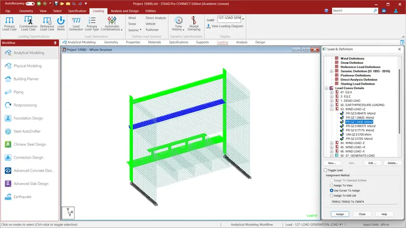
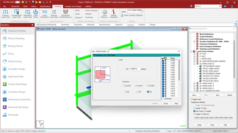
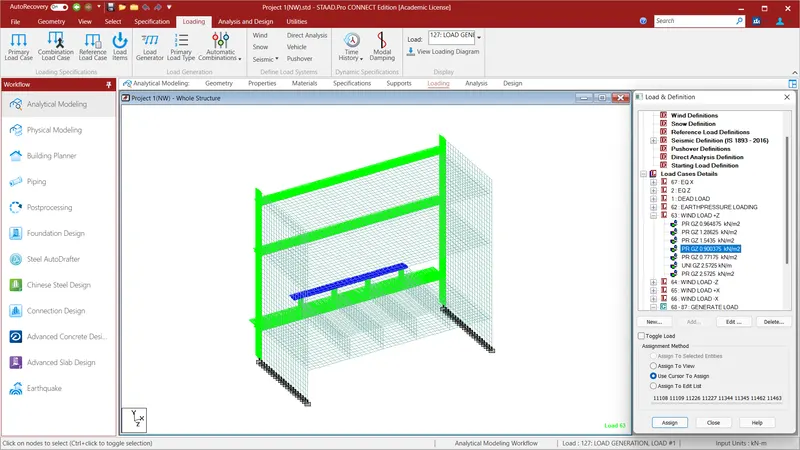
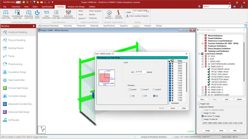
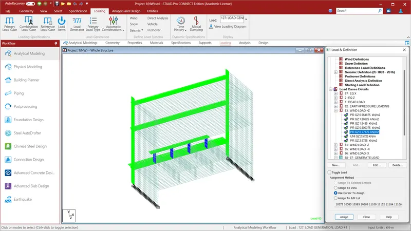
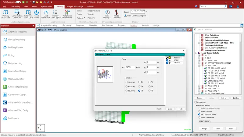
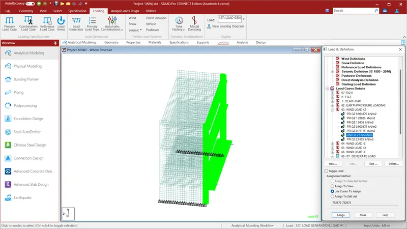
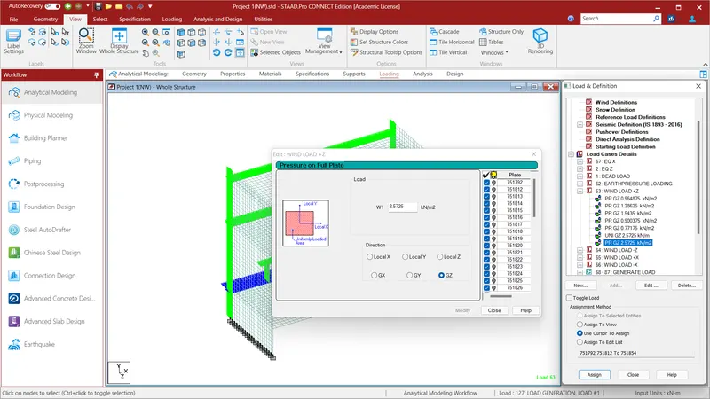
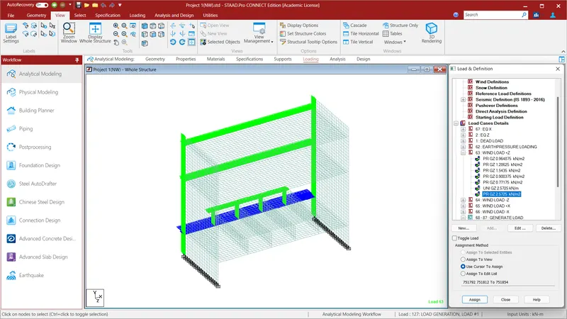
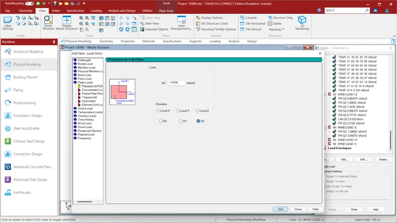
We have to aplly wind load in +X & -X Direction and +Z & -Z Direction. To do that go to Load Case Details and give the name as Wind Load +Z . Select the Wind Load +Z and click Add and go to the plate Loads and click Pressure on Full Plate and give the value as W1=0.964875KN/m^2 in Local Z Direction and click Add. Select the vertical plate in the Z direction or the plates facing toward Z Direction and select the plates . Since the thickness of those plates is 0.75m and wind pressure is 1.286.25KN/m^2 the load acting will be 0.75*1.286.25=0.964875KN/m^2. Select the Vertical Plates and Assign to Selected Plates and Assign and click Yes. Again Select the Wind Load +Z and click Add and go to the plate Loads and click Pressure on Full Plate and give the value as W1=1.28625KN/m^2 in Local Z Direction and click Add. Select the vertical plate in the Z direction or the plates facing toward Z Direction and select the plates . Since the thickness of those plates is 1m and wind pressure is 1.286.25KN/m^2 the load acting will be 1*1.286.25=1.28625KN/m^2. Select the top deckslab and Assign to Selected Plates and Assign and click Yes. Again Select the Wind Load +Z and click Add and go to the plate Loads and click Pressure on Full Plate and give the value as W1=1.5435KN/m^2 in Local Z Direction and click Add. Select the vertical plate in the Z direction or the plates facing toward Z Direction and select the plates . Since the thickness of those plates is 1.2m and wind pressure is 1.286.25KN/m^2 the load acting will be 1.2*1.286.25=1.28625KN/m^2. Select the top deckslab and Assign to Selected Plates and Assign and click Yes. Again Select the Wind Load +Z and click Add and go to the plate Loads and click Pressure on Full Plate and give the value as W1=0.900375KN/m^2 in Local Z Direction and click Add. Select the vertical plate in the Z direction or the plates facing toward Z Direction and select the plates . Since the thickness of those plates is 0.7m and wind pressure is 0.900375KN/m^2 the load acting will be 0.7*1.286.25=0.900375KN/m^2. Select the Metro deckslab and Assign to Selected Plates and Assign and click Yes. Again Select the Wind Load +Z and click Add and go to the plate Loads and click Pressure on Full Plate and give the value as W1=0.77175KN/m^2 in Local Z Direction and click Add. Select the vertical plate in the Z direction or the plates facing toward Z Direction and select the plates . Since the thickness of those plates is 0.6m and wind pressure is 1.286.25KN/m^2 the load acting will be 0.6*1.286.25=0.77175KN/m^2. Select the Metro Wall and Assign to Selected Plates and Assign and click Yes. Again Select the Wind Load +Z and click Add and go to the plate Loads and click Pressure on Full Plate and give the value as W1=1.28625KN/m^2 in Local Z Direction and click Add. Select the vertical plate in the Z direction or the plates facing toward Z Direction and select the plates . Since the thickness of those plates is 2m and wind pressure is 1.286.25KN/m^2 the load acting will be 2*1.286.25=2.5725KN/m^2. Select the rectangular beams and Assign to Selected Plates and Assign and click Yes.Again Select the Wind Load +Z and click Add and go to the plate Loads and click Pressure on Full Plate and give the value as W1=1.28625KN/m^2 in Local Z Direction and click Add. Select the vertical plate in the Z direction or the plates facing toward Z Direction and select the plates . Since the thickness of those plates is 2m and wind pressure is 1.286.25KN/m^2 the load acting will be 2*1.286.25=2.5725KN/m^2. Select the top deckslab and Assign to Selected Plates and Assign and click Yes.
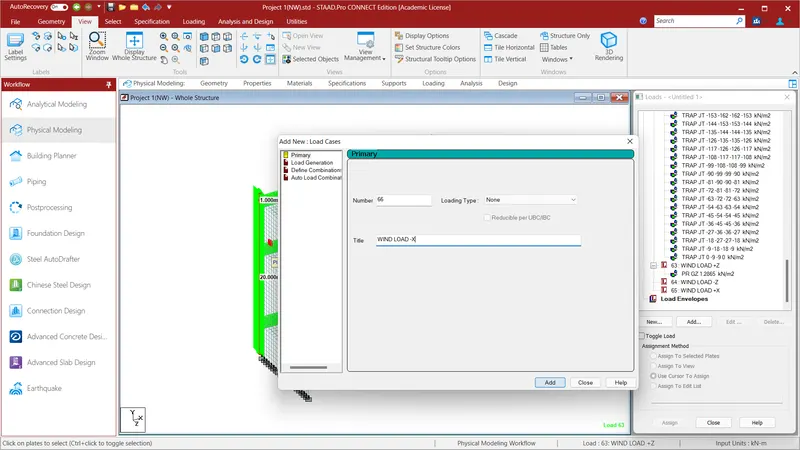
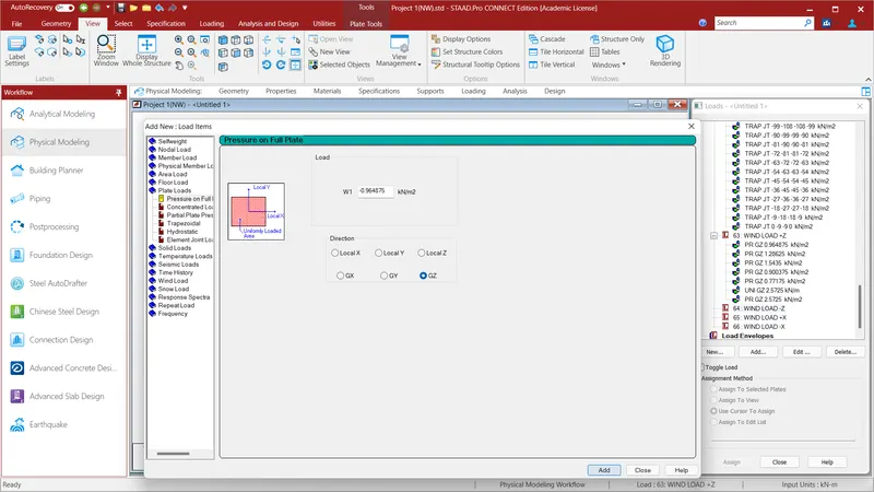
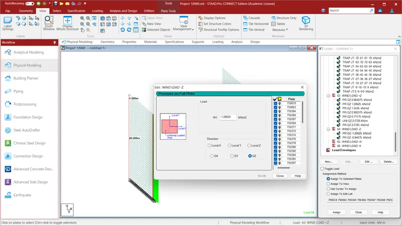
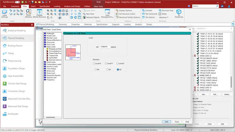
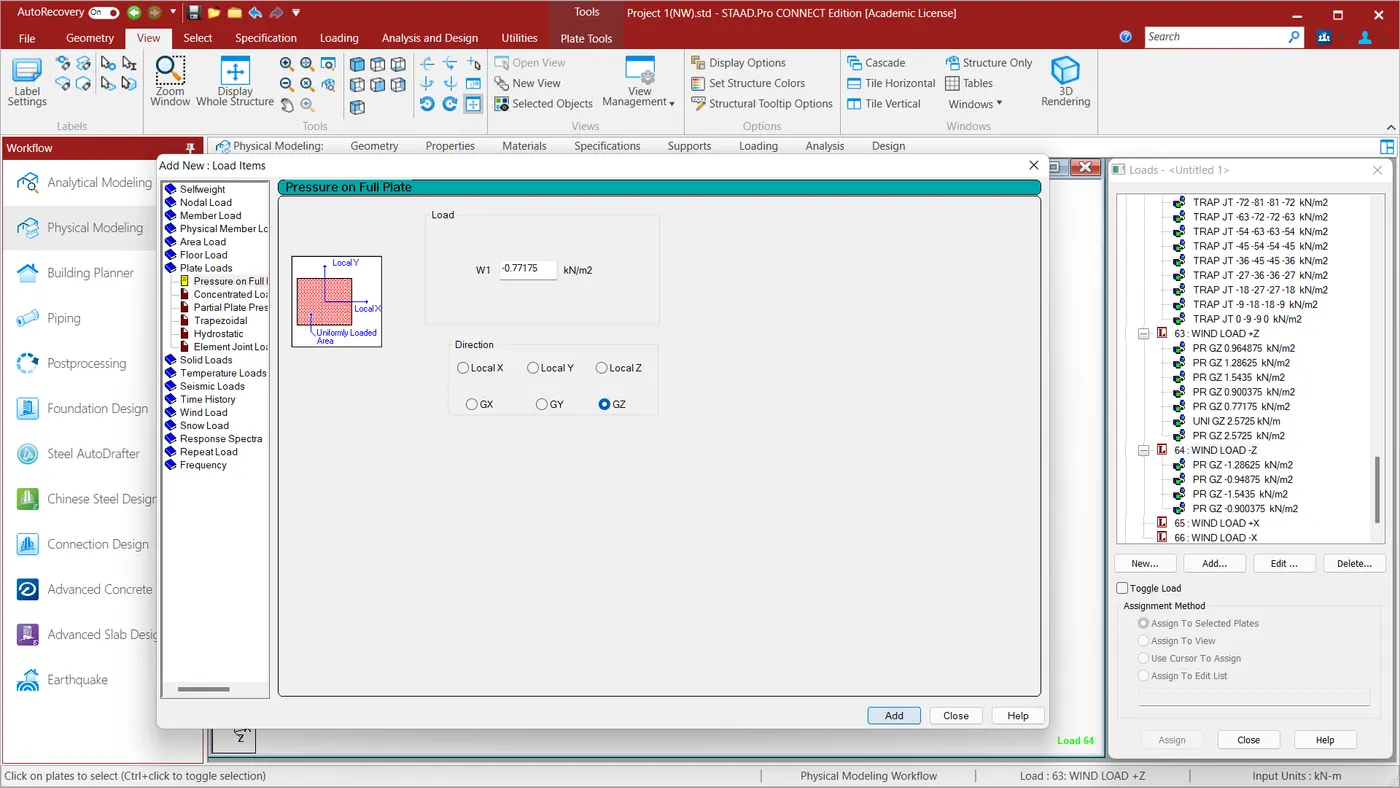
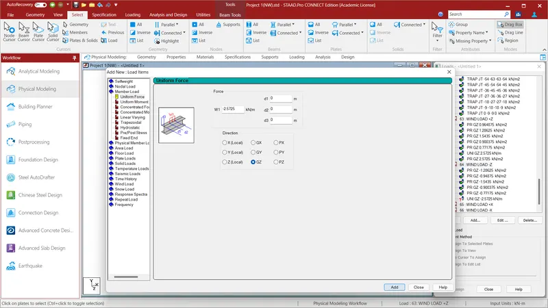
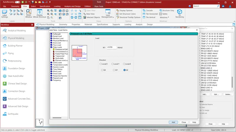
Go to Load Case Details and give the name as Wind Load -Z . Select the Wind Load -Z and click Add and go to the plate Loads and click Pressure on Full Plate and give the value as W1=-0.964875KN/m^2 in Local Z Direction and click Add. Select the vertical plate in the Z direction or the plates facing toward Z Direction and select the plates . Since the thickness of those plates is 0.75m and wind pressure is 1.286.25KN/m^2 the load acting will be 0.75*1.286.25=0.964875KN/m^2. Select the Vertical Plates and Assign to Selected Plates and Assign and click Yes. Again Select the Wind Load -Z and click Add and go to the plate Loads and click Pressure on Full Plate and give the value as W1=-1.28625KN/m^2 in Local Z Direction and click Add. Select the vertical plate in the Z direction or the plates facing toward Z Direction and select the plates . Since the thickness of those plates is 1m and wind pressure is 1.286.25KN/m^2 the load acting will be 1*1.286.25=1.28625KN/m^2. Select the top deckslab and Assign to Selected Plates and Assign and click Yes. Again Select the Wind Load -Z and click Add and go to the plate Loads and click Pressure on Full Plate and give the value as W1=-1.5435KN/m^2 in Local Z Direction and click Add. Select the vertical plate in the Z direction or the plates facing toward Z Direction and select the plates . Since the thickness of those plates is 1.2m and wind pressure is 1.286.25KN/m^2 the load acting will be 1.2*1.286.25=1.28625KN/m^2. Select the top deckslab and Assign to Selected Plates and Assign and click Yes. Again Select the Wind Load -Z and click Add and go to the plate Loads and click Pressure on Full Plate and give the value as W1=-0.900375KN/m^2 in Local Z Direction and click Add. Select the vertical plate in the Z direction or the plates facing toward Z Direction and select the plates . Since the thickness of those plates is 0.7m and wind pressure is 0.900375KN/m^2 the load acting will be 0.7*1.286.25=0.900375KN/m^2. Select the Metro deckslab and Assign to Selected Plates and Assign and click Yes. Again Select the Wind Load -Z and click Add and go to the plate Loads and click Pressure on Full Plate and give the value as W1=-0.77175KN/m^2 in Local Z Direction and click Add. Select the vertical plate in the Z direction or the plates facing toward Z Direction and select the plates . Since the thickness of those plates is 0.6m and wind pressure is 1.286.25KN/m^2 the load acting will be 0.6*1.286.25=0.77175KN/m^2. Select the Metro Wall and Assign to Selected Plates and Assign and click Yes. Again Select the Wind Load -Z and click Add and go to the plate Loads and click Pressure on Full Plate and give the value as W1=-1.28625KN/m^2 in Local Z Direction and click Add. Select the vertical plate in the Z direction or the plates facing toward Z Direction and select the plates . Since the thickness of those plates is 2m and wind pressure is 1.286.25KN/m^2 the load acting will be 2*1.286.25=2.5725KN/m^2. Select the rectangular beams and Assign to Selected Plates and Assign and click Yes.Again Select the Wind Load -Z and click Add and go to the plate Loads and click Pressure on Full Plate and give the value as W1=-1.28625KN/m^2 in Local Z Direction and click Add. Select the vertical plate in the Z direction or the plates facing toward Z Direction and select the plates . Since the thickness of those plates is 2m and wind pressure is 1.286.25KN/m^2 the load acting will be 2*1.286.25=2.5725KN/m^2. Select the top deckslab and Assign to Selected Plates and Assign and click Yes.
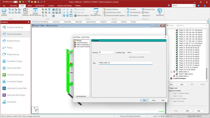
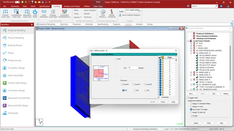
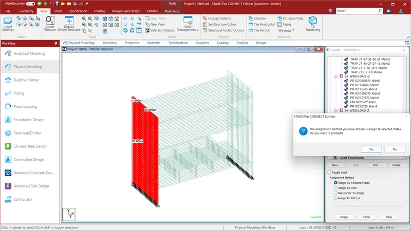
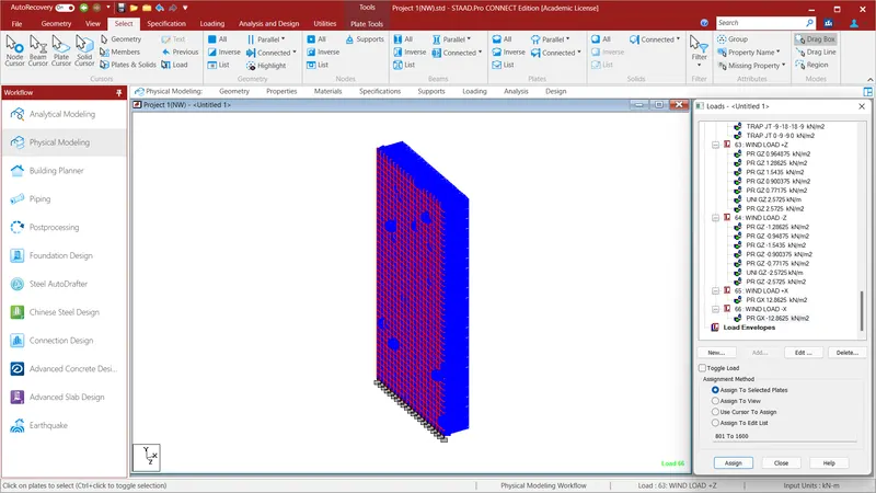
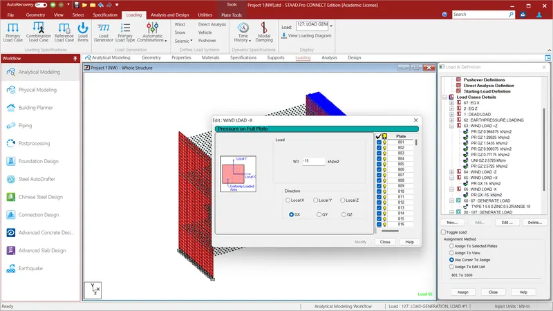
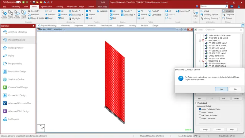
Go to Load Case Details and give the name as Wind Load +X . Select the Wind Load +X and click Add and go to the plate Loads and click Pressure on Full Plate and give the value as W1=15KN/m^2 {Plate thickness is 0.75m and height of the vertical wall is 20m}.and click Add. Select the Assign to Selected Plates and Assign and click YES.Go to Load Case Details and give the name as Wind Load -X . Select the Wind Load -X and click Add and go to the plate Loads and click Pressure on Full Plate and give the value as W1=-15KN/m^2 {Plate thickness is 0.75m and height of the vertical wall is 20m}.and click Add. Select the Assign to Selected Plates and Assign and click YES.We have Assign loading to the Dead Load, IRS Live Load,Earth pressure load , wind load and seismic loads for the bridge structure.
RESULT:
After Loading go to the loading and Analysis option and select the analysis Command and click ADD and run the analysis to get the required results for the Staad File.
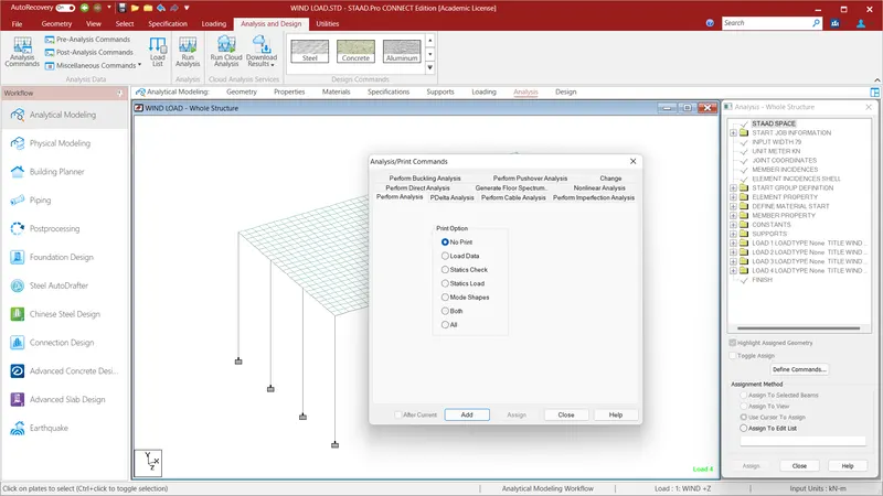
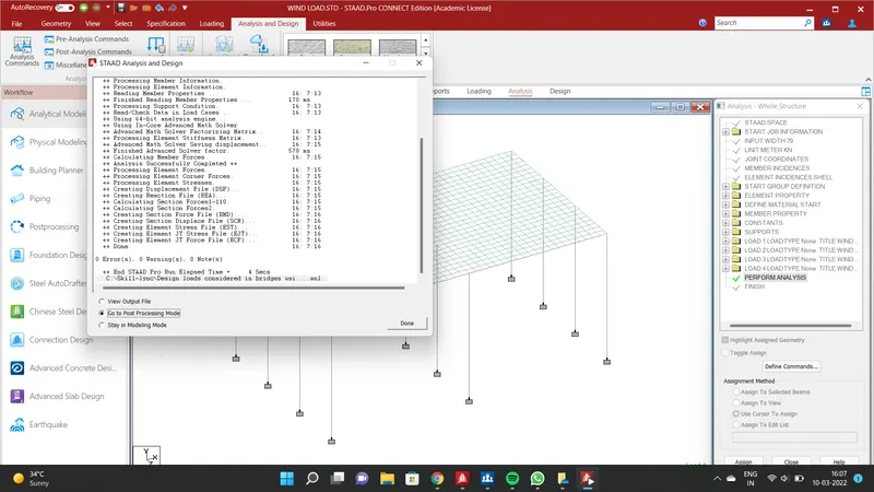
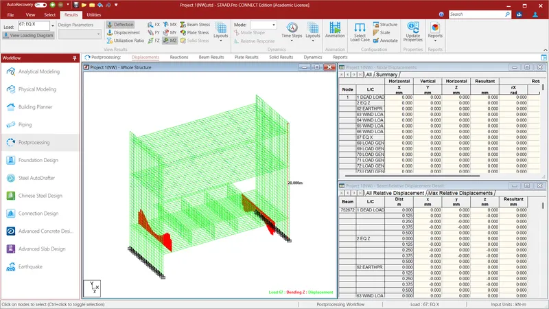
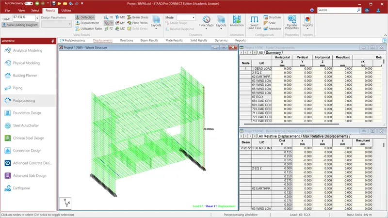
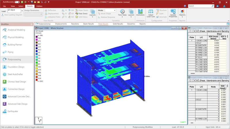
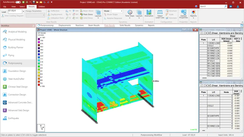
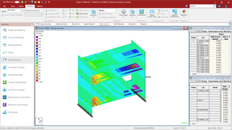
These are the results obtained due to the stresses acting on the plates and beams.
REPORT:
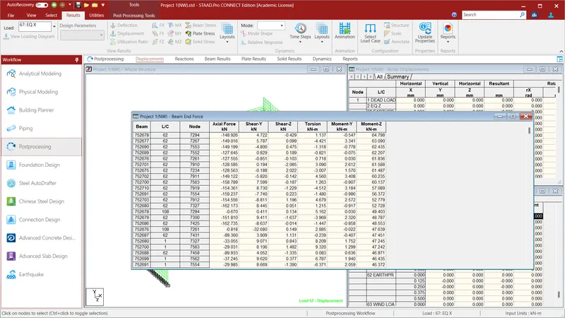
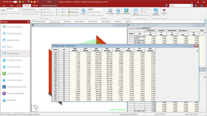
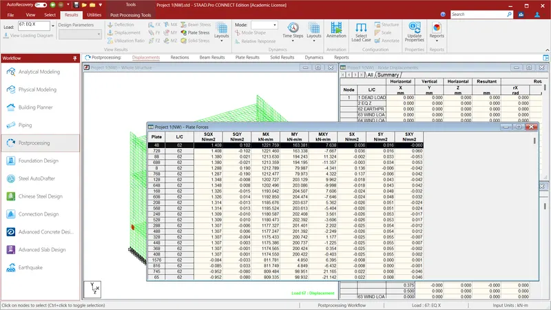
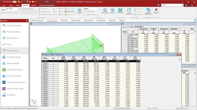
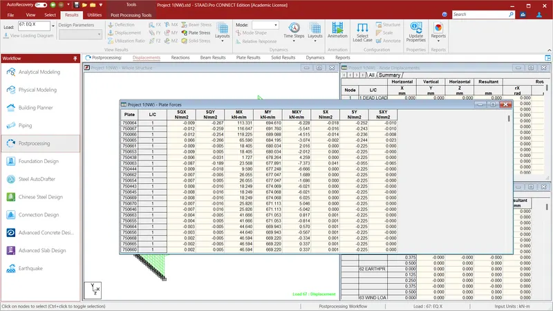
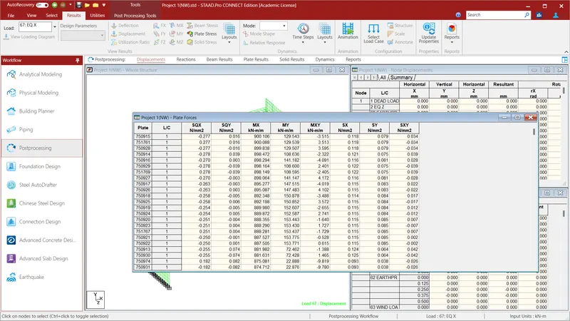
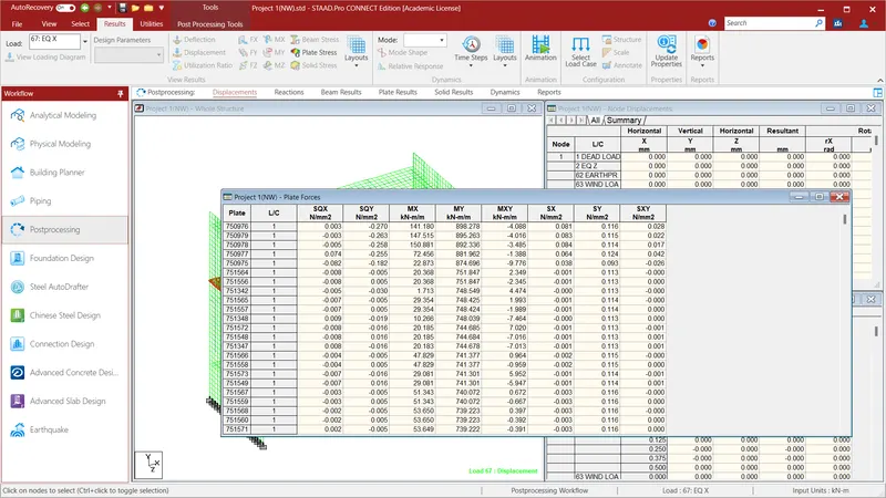
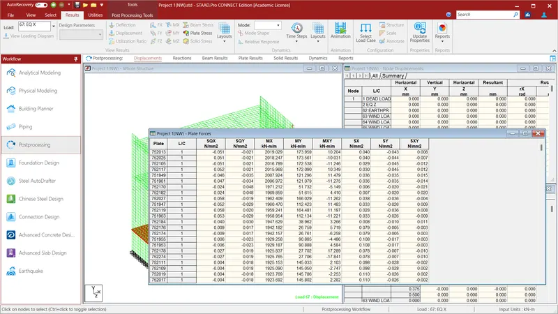
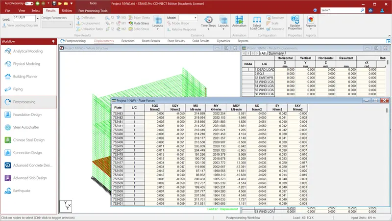
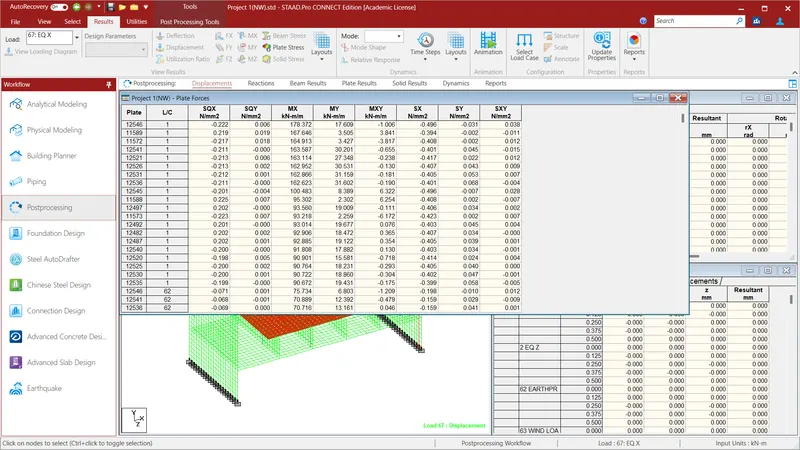
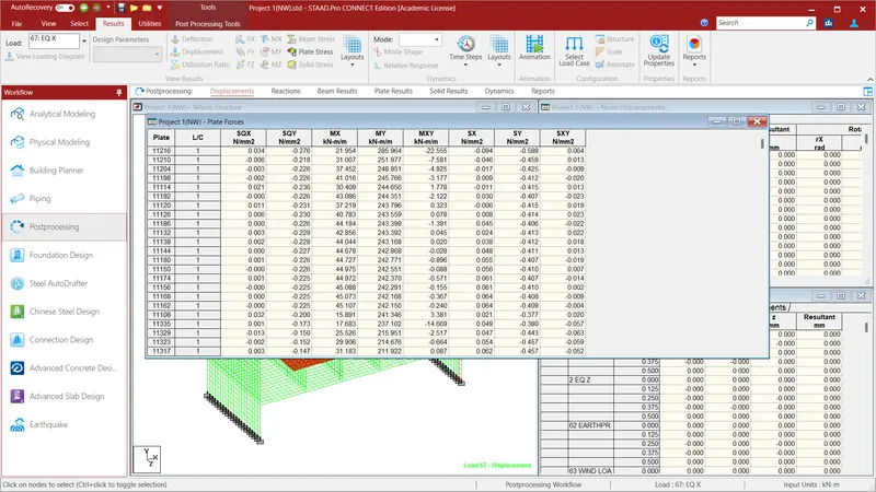
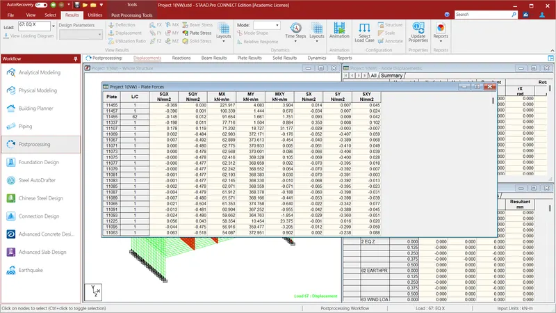
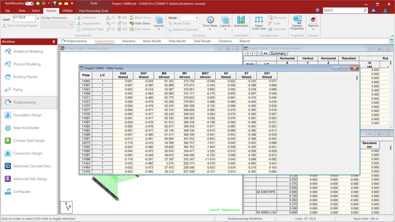
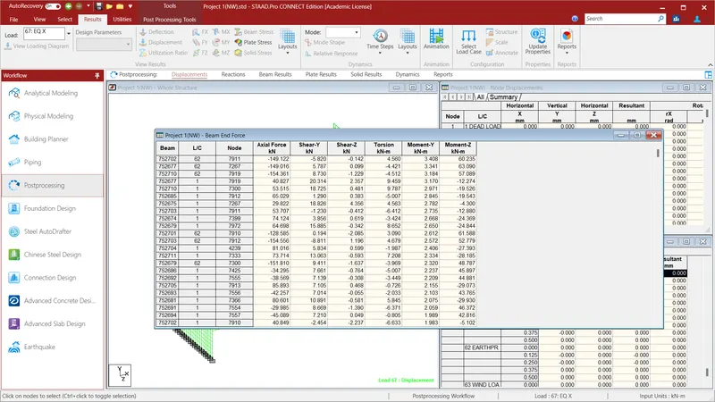
The report is obtained in the Staad File and are mentioned above in the above pictures.