Project 1
Model
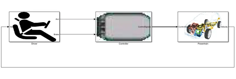
Powertrain
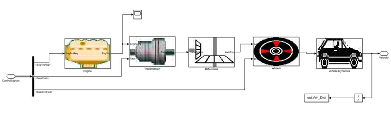
Vehicle Dynamics
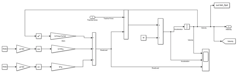
Engine
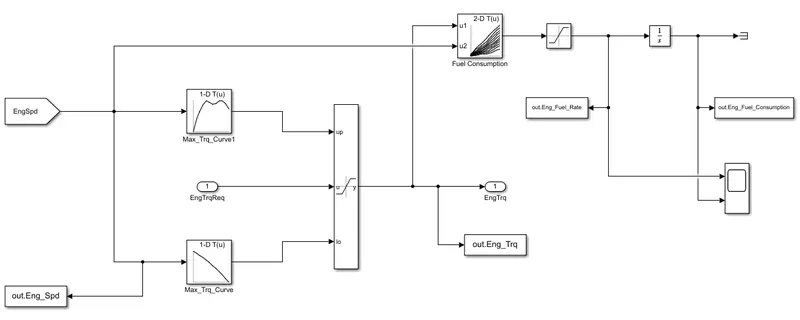
Parameters
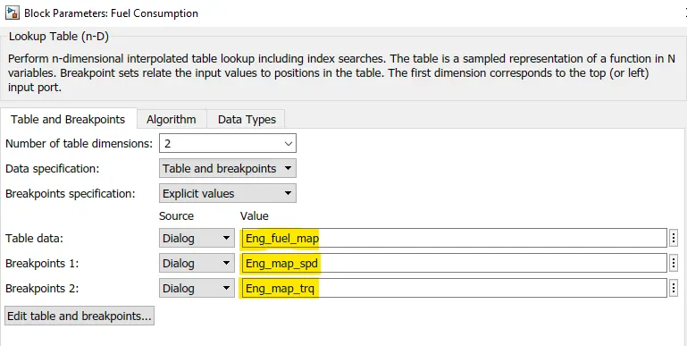
a) Fuel consumption
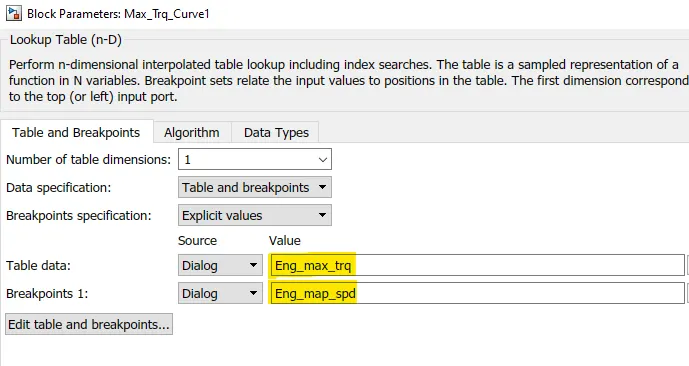
b) Maximum Torque Curve
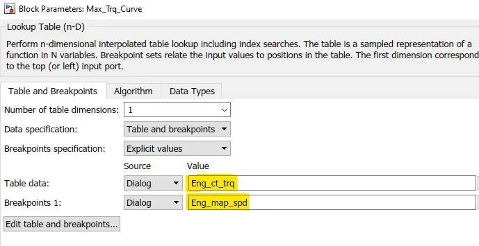
c) Minimum Torque Curve
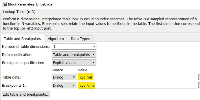
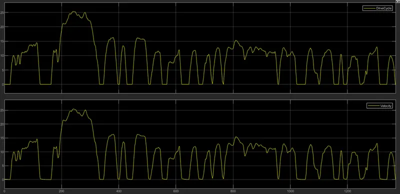
d) Drive Cycle
Result
1) After give UDDS drive cycle as input we get the following result.
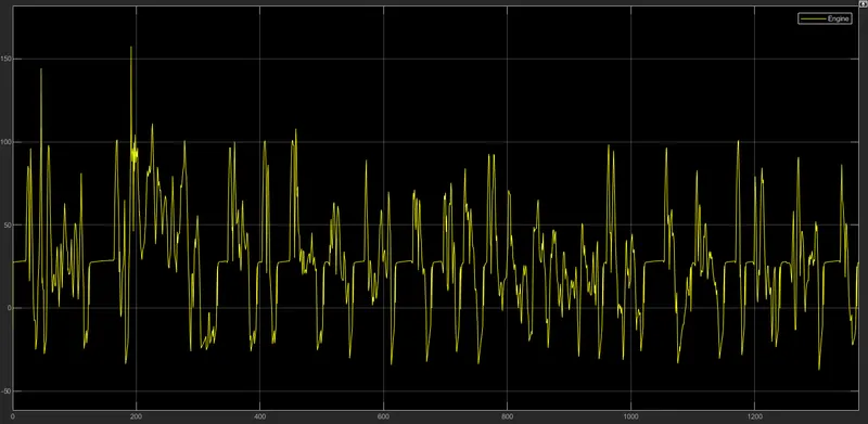
Engine
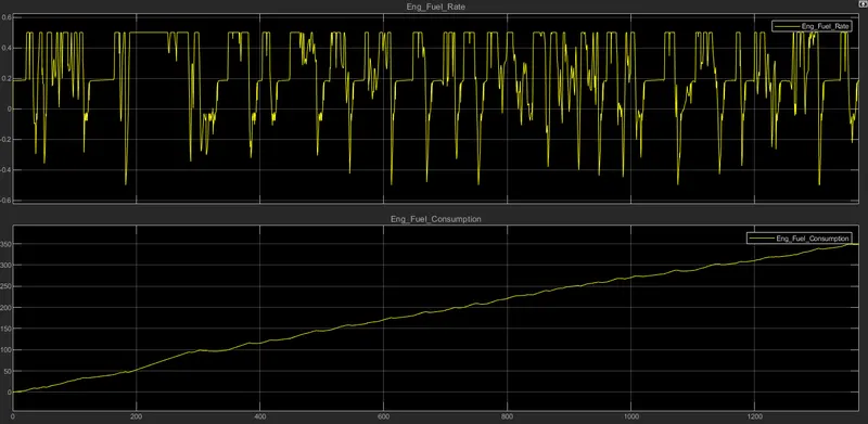
Engine Fuel rate and Fuel Consumption
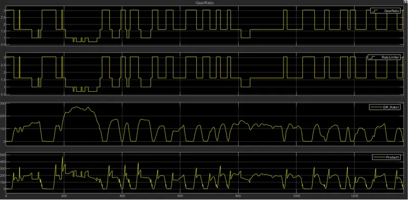
Gear ratio, Gear ratio(Rate limiter), Transmission output speed, Transmission input speed
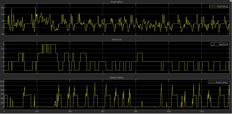
Engine Torque required, Transmission gear, Brake torque required
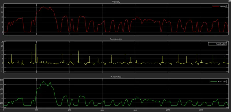
Velocity, Acceleration and Road load
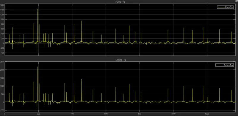
Pump Torque and Turbine Torque
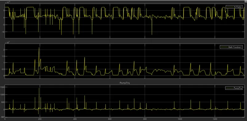
K-factor, Square of pump speed, Pump Torque
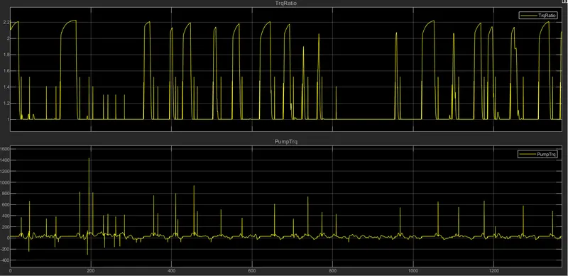
Torque ratio and Pump Torque
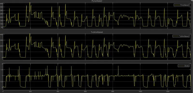
Pump Speed, Turbine Speed, Turbine Speed/Pump speed
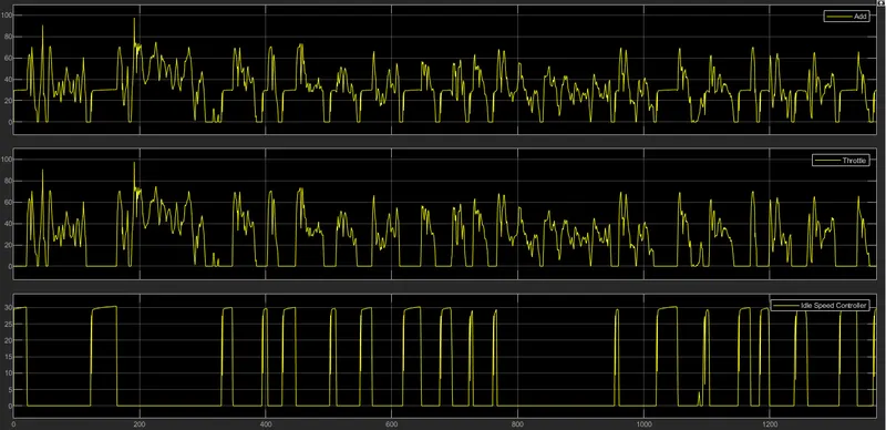
Add(Throttle Speed+Ideal Speed), Throttle Speed, Ideal Speed
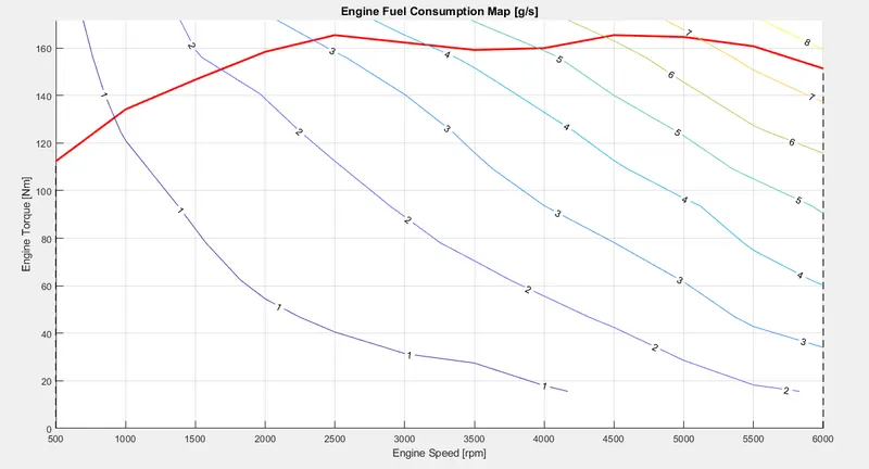
Fuel consumption map 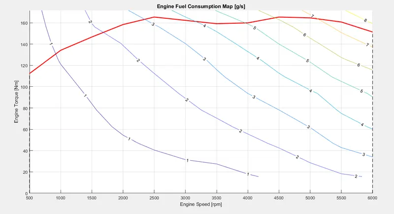
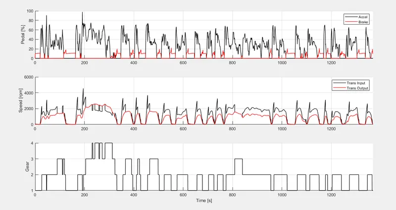
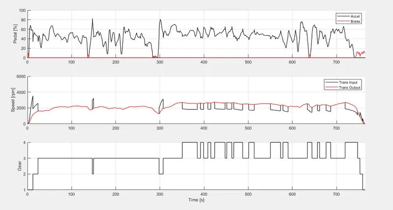
Acceleration and Brake pedal, Transmission input and output speed, Transmission gear
2) HWFET Drive cycle
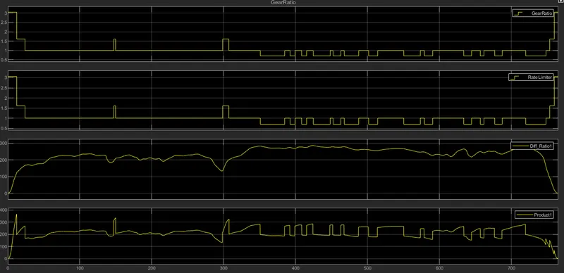
Gear ratio, Gear ratio(Rate limiter), Transmission output speed, Transmission input speed
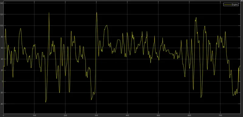
Engine
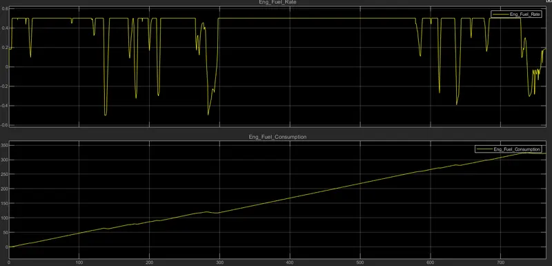
Engine Fuel rate and Fuel Consumption
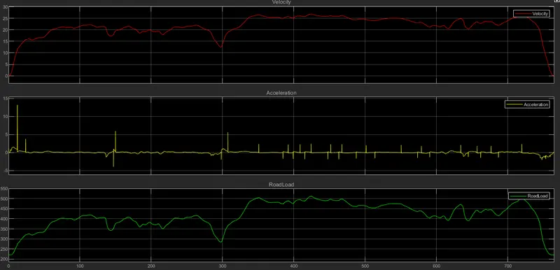
Velocity, Acceleration and Road load
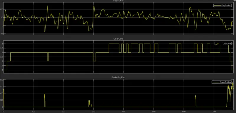
Engine Torque required, Transmission gear, Brake torque required
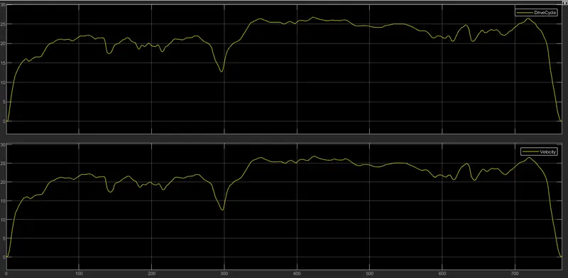
Drive Cycle
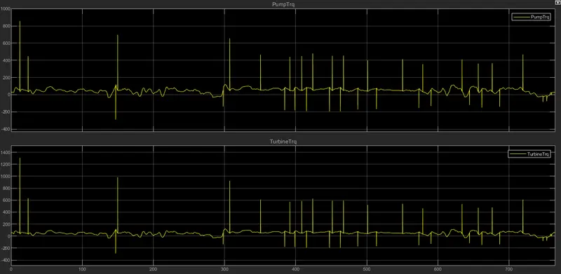
Pump Torque and Turbine Torque
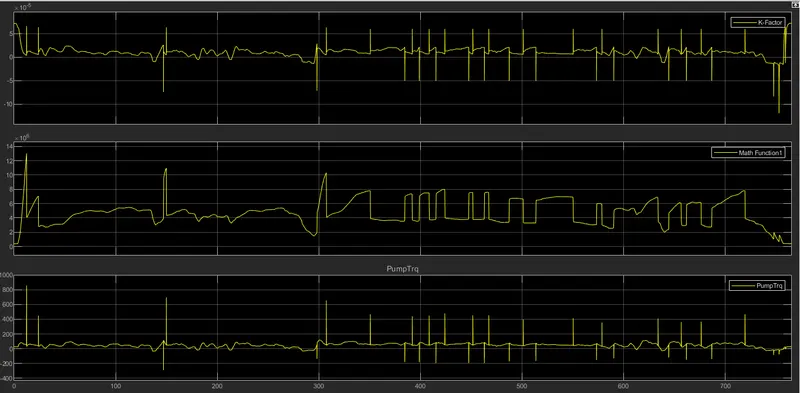
K-factor, Square of pump speed, Pump Torque
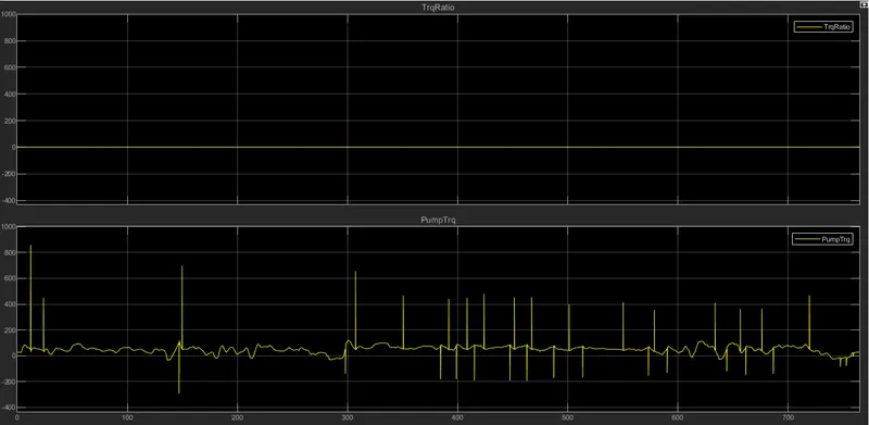
Torque ratio and Pump Torque
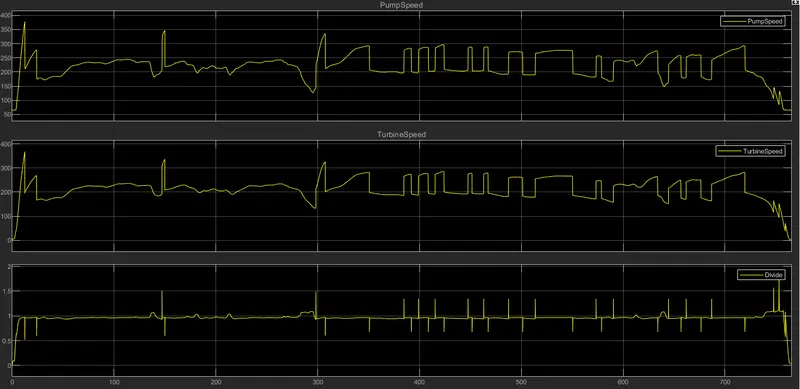
Pump Speed, Turbine Speed, Turbine Speed/Pump speed
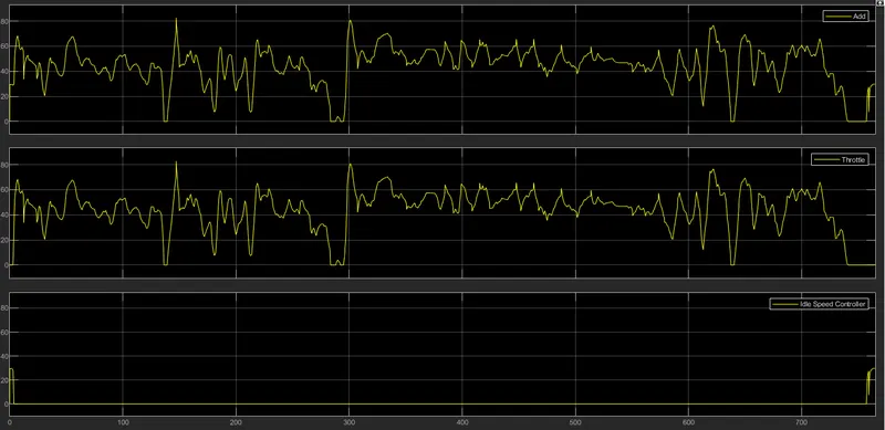
Add(Throttle Speed+Ideal Speed), Throttle Speed, Ideal Speed
Fuel consumption map
Acceleration and Brake pedal, Transmission input and output speed, Transmission gear
Observation
1) The EPA Urban Dynamometer Driving Schedule (UDDS) is commonly called the "LA4" or "the city test" and represents city driving conditions. It is used for light duty vehicle testing.
The Highway Fuel Economy Driving Schedule (HWFET) represents highway driving conditions under 60 mph.
2)The percentage of Acceleration pedal in UDDS drive cycle reaches up to 95% whereas in HWFET drive cycle it is applied up to 80%.
Brake is applied quite often in UDDS drive cycle and almost negligible in HWFET drive cycle.
3) Velocity is divided by tire radius (or rolling radius) to get Wheel Speed. This wheel speed is multiplied with final drive ratio to get Tansmission Output Speed. This output speed is multiplied with gear ration which give Transmission input speed in rpm. The difference between the transmission input and output speed can be seen in the graph above for drive cycles.