Project 1 - 2D meshing on the instrumental Panel
AIM; To extract the Midsurface to the given model and generate the meshing according to the given quality criteria and apply thickness to the components.
PROCEDURE;
- Import the model in to the Ansa GUI area.
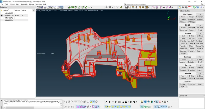
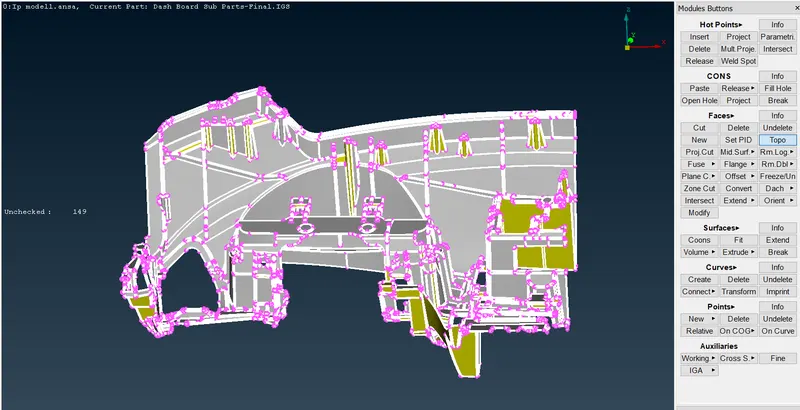
2. we need to use the topo option to clean up the single cons and free edges present in the CAD model.It can be accessed via Faces > Topo in the topo module. All the cons are selected and click on middle mouse button to conform the operation.
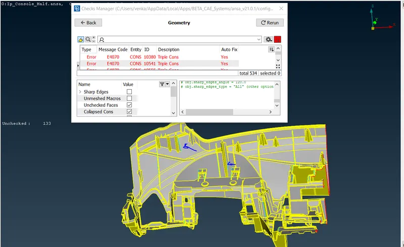
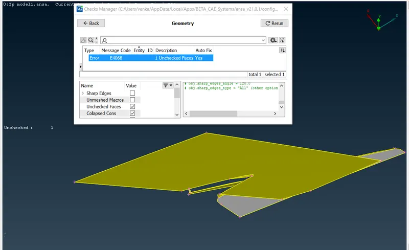
3. After that, we need to carry out a geometry check and fix all the Errors. Now go to the Tool options bar where we select the Checks > Geometry we can execute checks of certain defects that can be selected from the menu and it will shows as all errors present in the model. After detection, we can select all the defects and right-click > fix to fix them.
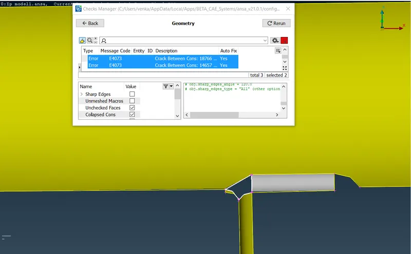
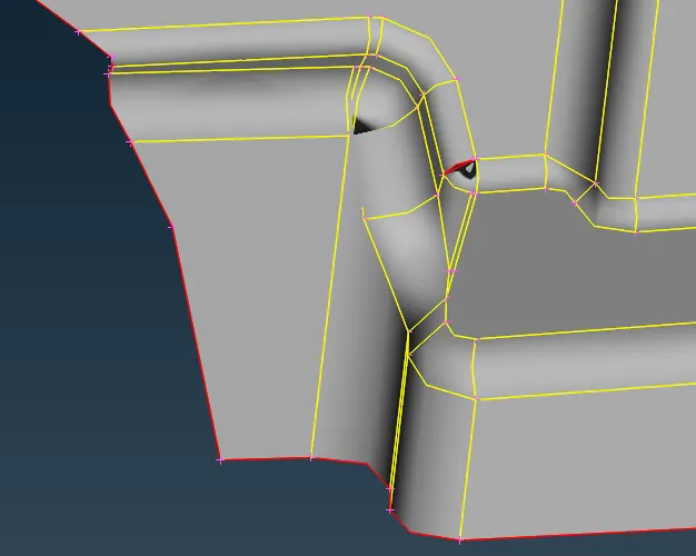
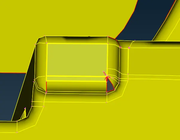
- The fix option will not able to clear all errors and some of them we need to fix it manually.Here below there are showing a lot of triple cons and we will fix it by releasing cons and topo on that particular area.
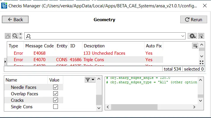
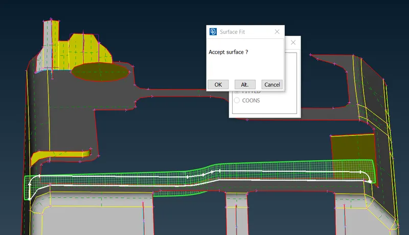
Including the triple cons they are also forming some cracks between the cons and we have to fix by creating the New surface on the crack regions of the body.
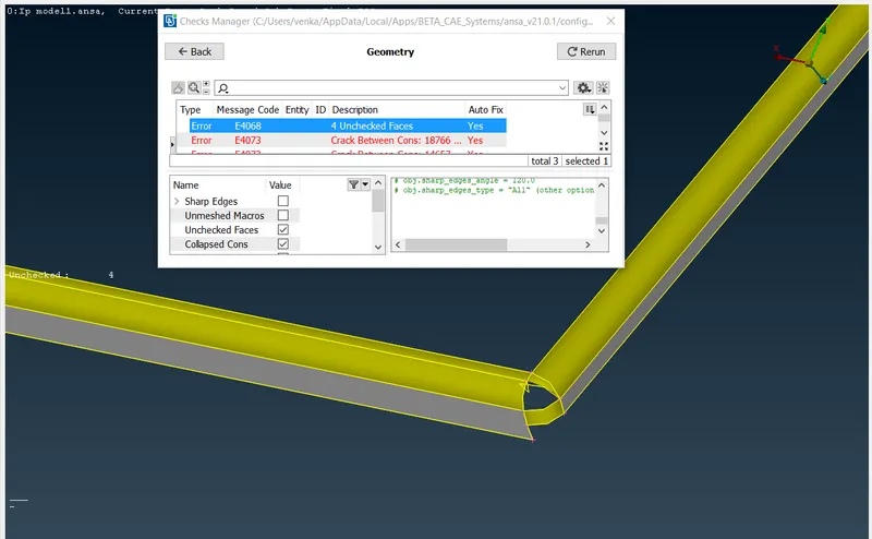
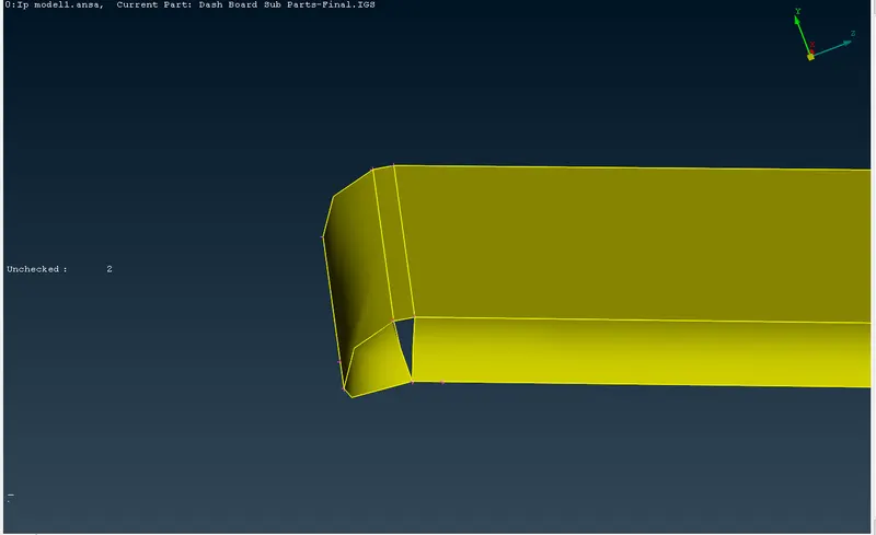
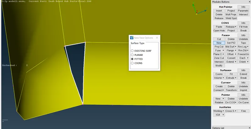
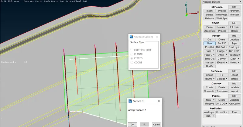
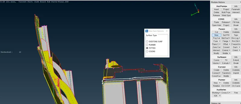
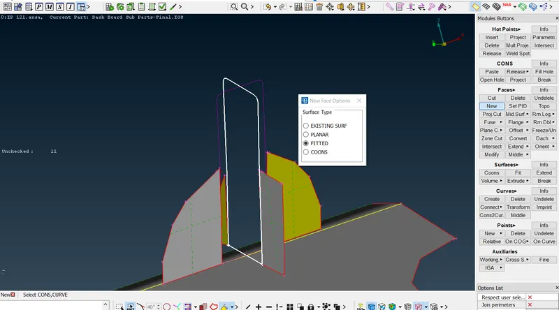
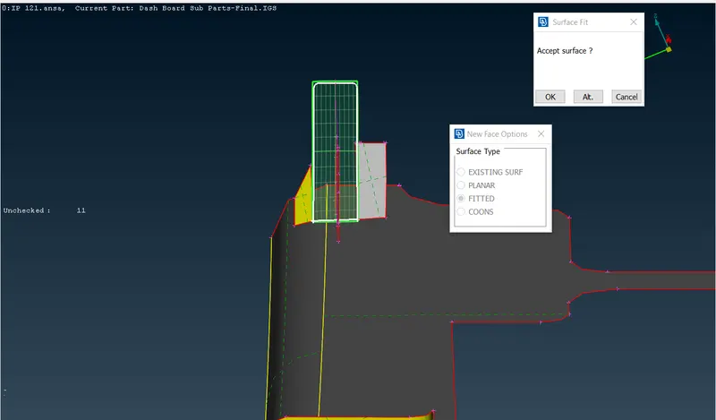
Creating the new surfaces >Faces>New>fitted and select the regions to fill the surfaces.
4. Now generate the midsurfaces to the given model. There are multiple ways to do this, We shall be using the Skin,middle and the offset tools for this challenge.For the base of this model we use the offset tool Faces > Offset, it will ask us to select the surfaces to offset. We can select the surfaces on one side of the component. After that, we can add the offset value to the model and it will show the direction of the offset in the form of an arrow. If it is in the opposite direction of the required offset, the offset value needs to be in the negatives. If we proceed, the surface will be offset and created a midsurface to the model.
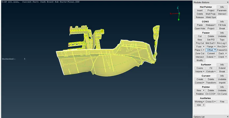
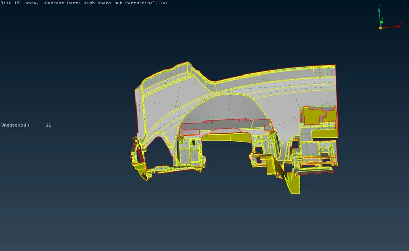
After creating the midsurface, By using the Set Pid we have to create an seperate properties for each of these midsurfaces as soon as you create them.
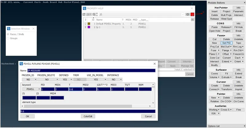
We have to check the generated midsurface properly, because some times it will form cracks or deletion of the particular surfaces and we take care those errors and fix it properly.
Middle Midsurface;
5. The middle tool is especially useful for generating midsurfaces for the various ribs in this model. It can be accessed by going to Faces > Middle. After that, we just need to select either side of the rib and that generates the middle surface.
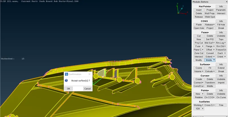
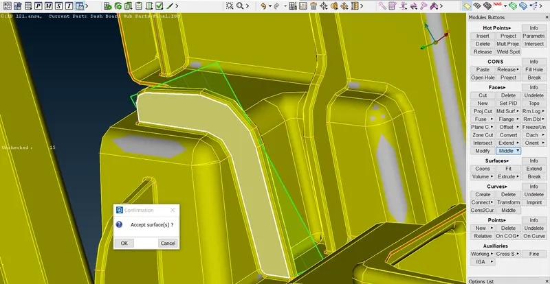
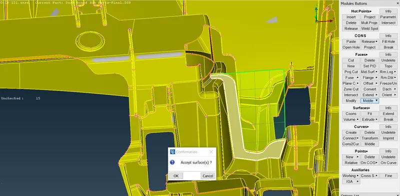
6.Some of the ribs will not generate midsurface properly by using the faces>middle option, For avoiding those corrections we use the Curves > Middle Option and for that select the lines of the ribs on both sides, where it will creates an curve in middle of the ribs.
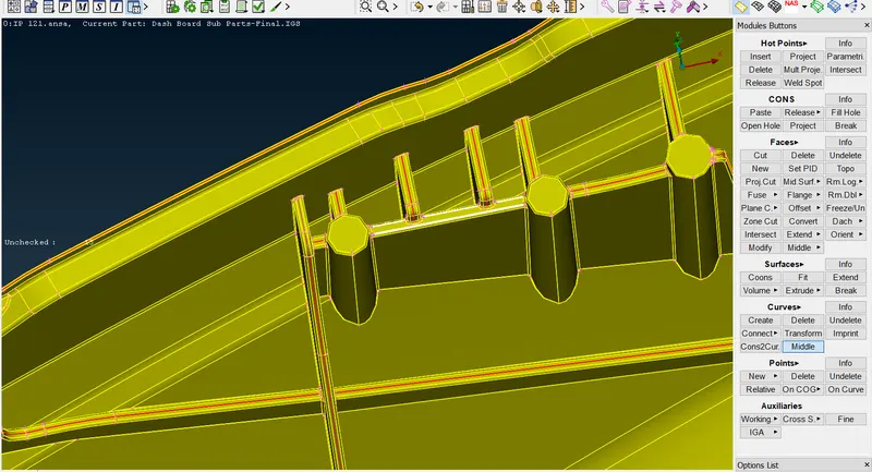
join curves the curves by using the Curves>Create from the one end to another end to form a new curve between them.
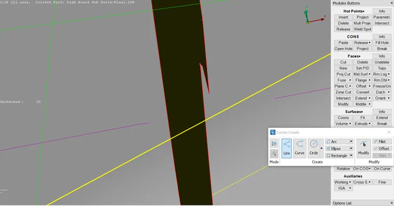
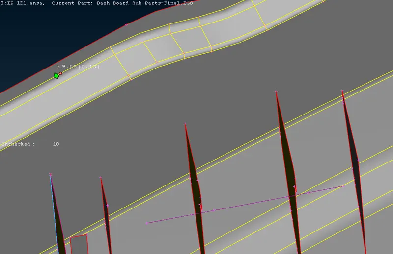
We use the Connect multi opton in order to connect the multiple curves to the single curve.
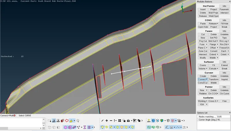
By using the Cons> project option, we have to project the curve to the base surface and create the new surface in between them.
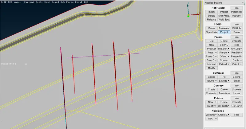
Con2curve;
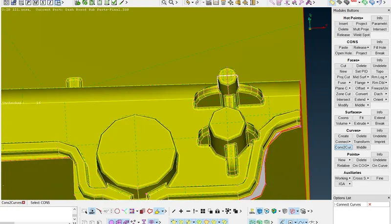
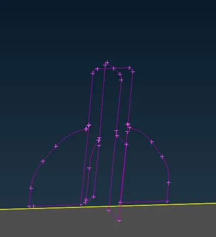
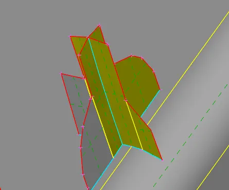
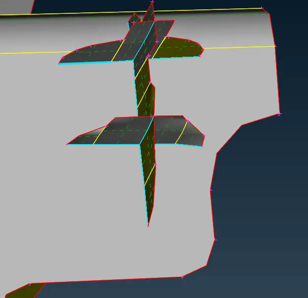
7.For the doghouses, the midsurface for them can be captured using the cross pattern, By making the cuts on them.
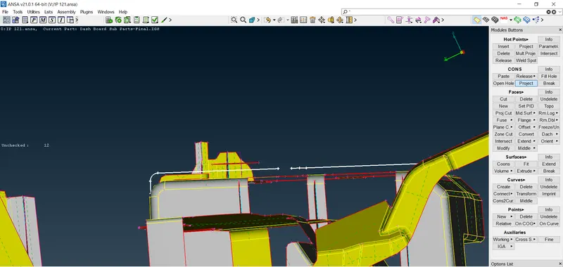
The Cons2Curves tool helps to create an midsuface for these type of components by selecting the outer curve lines of the doghouses. Simply clicking the outline and middle-clicking on them generates the curves.
Now we have to create the new surface to those curves.
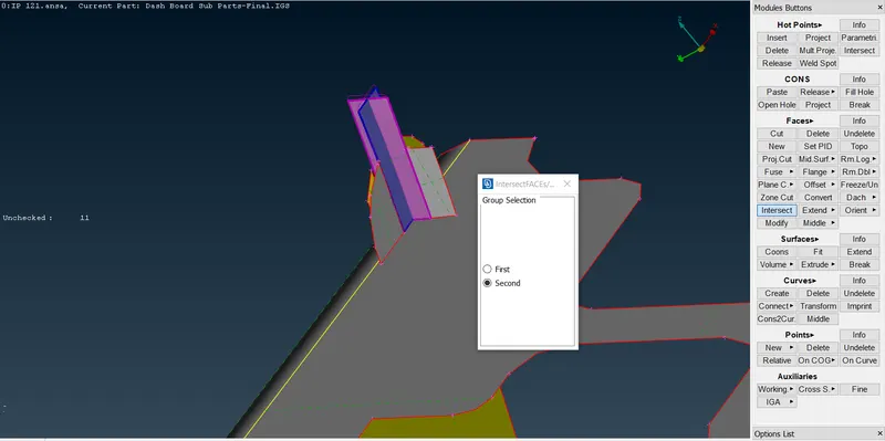
Intersect helps to define the intersections between the two groups of faces and connect the surfaces properly.
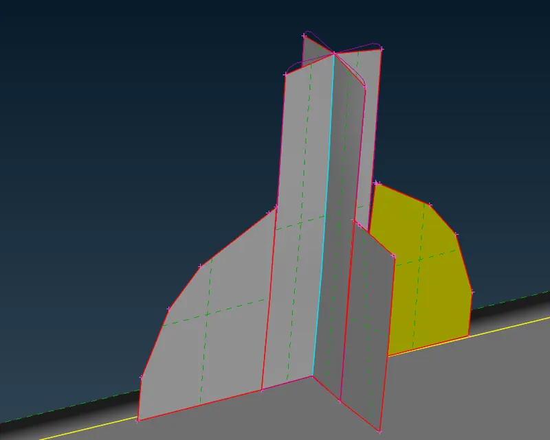
These option will use for connecting the two faces and aslo useful for the avoiding the extra forming faces on them.
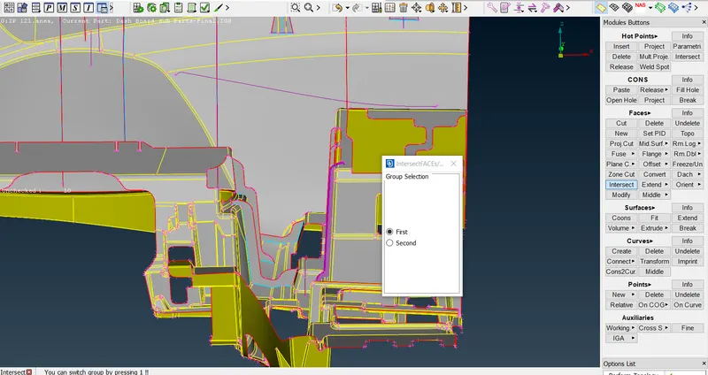
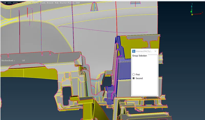
Delete the Extra surfaces by intersecting the faces on them.
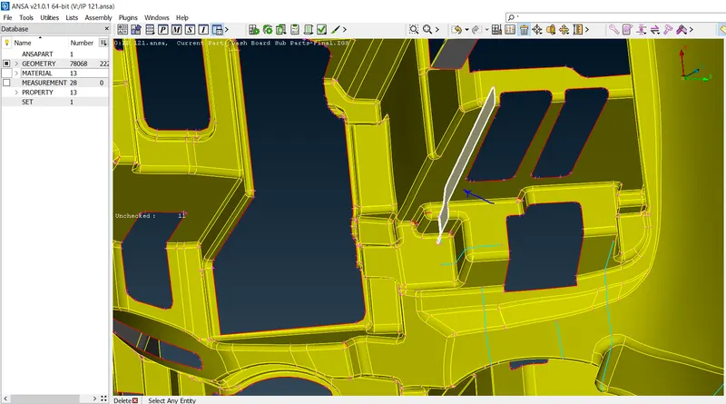
8.After extracting all the midsurfaces, we can go ahead and extend them to each other to join them with their adjacent base Surfaces. That is done by using the Faces > Extend tool and selecting target surface.
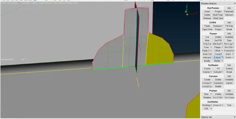
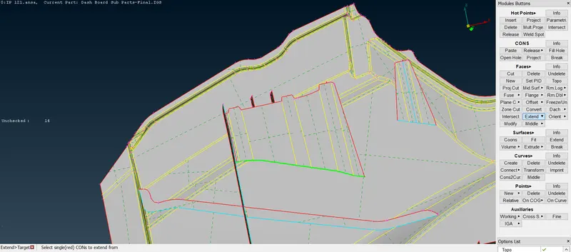
9.Now, having generated midsurfaces for the entire component, we can proceed with meshing. Before meshing, we need to set the target length through the perimeter > length.
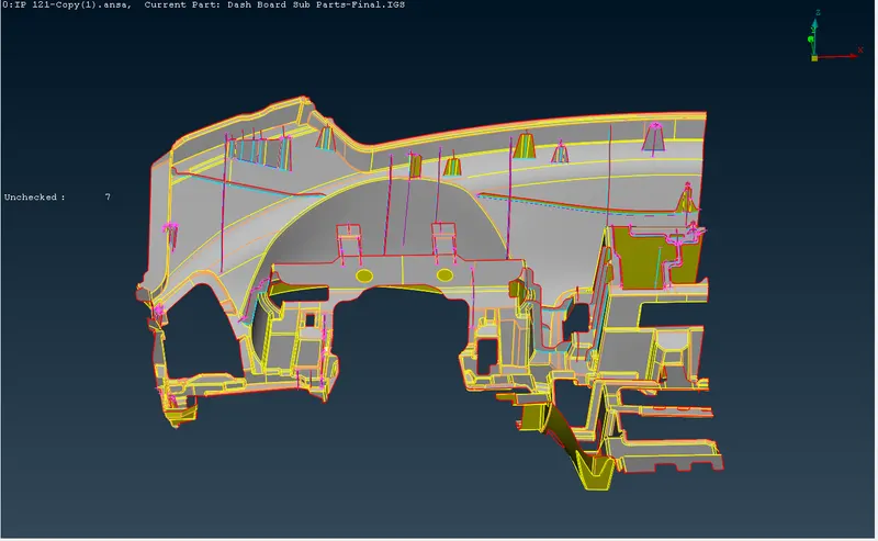
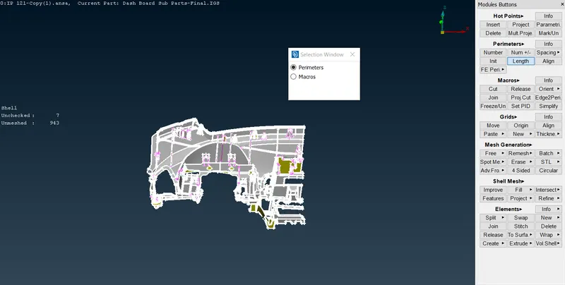
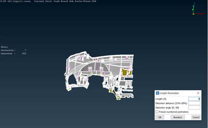
10.Before to start the Meshing, we could clear all the unwanted construction lines and fillet regions which are failing the minimum element length.Because it will lead to form an element failures quality criteria.
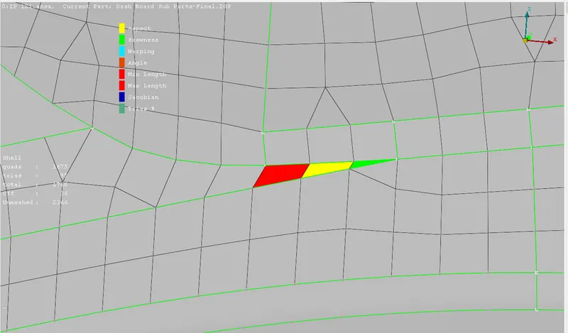
Measure the construction lines and toggle or remove those lines by using the cut and conforming the right click on the mouse.
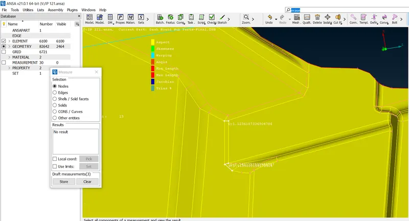
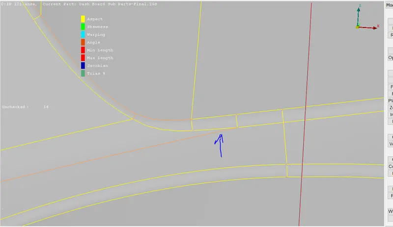
Now below the figure shows the good mesh flow and quality by comparing the above figure.
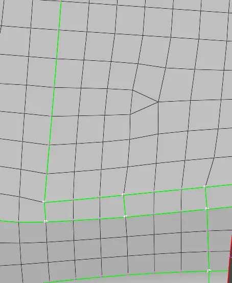
11.We can the start meshing to the entire component using Mesh Generation > Best or spot mesh from the Mesh module. we can make use of the reconstruct tool Shell Mesh > Reconstruct to generate a better mesh if the initial mesh is not proper.
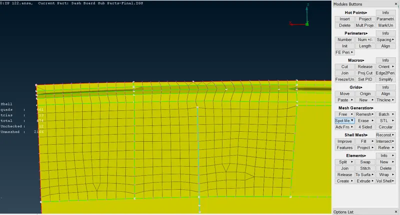
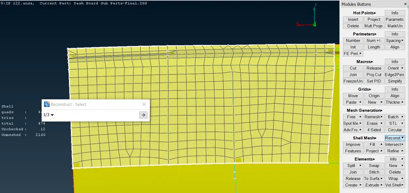
After using the reconstruction, the flow of an mesh is good and also it will avoid the trias on the mesh.
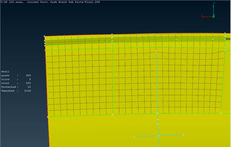
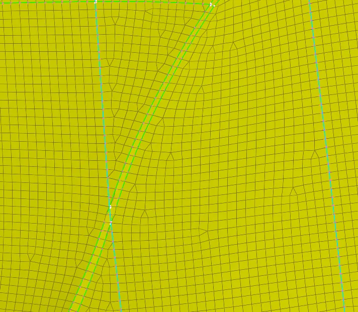
12.Sometimes, the reconstruct tool doesn't work in getting rid of some trias. Trias in some regions are okay but certain types of trias need to be avoided like opposite trias , trias touching feature lines,Back to back trias. These Trias can be eliminated by using the swap, split, join, paste and smooth tools.
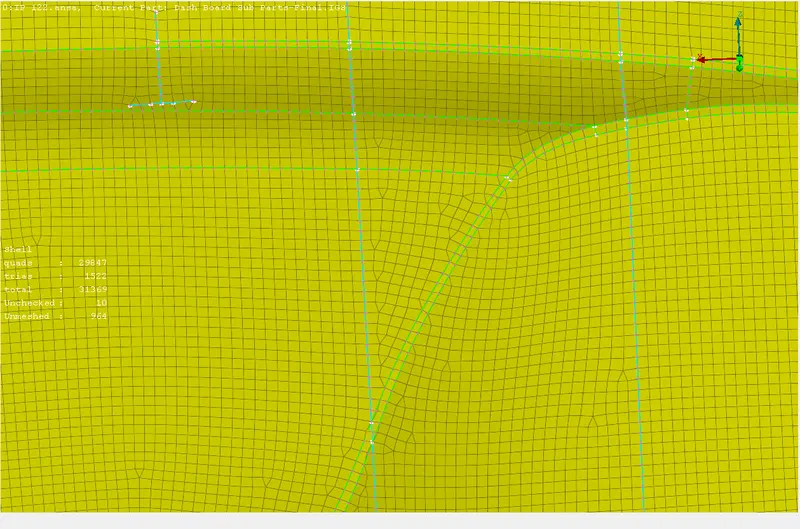
After cleraing all the trias near edges and back to back trais formation, it will shows an non uniform of the mesh part.
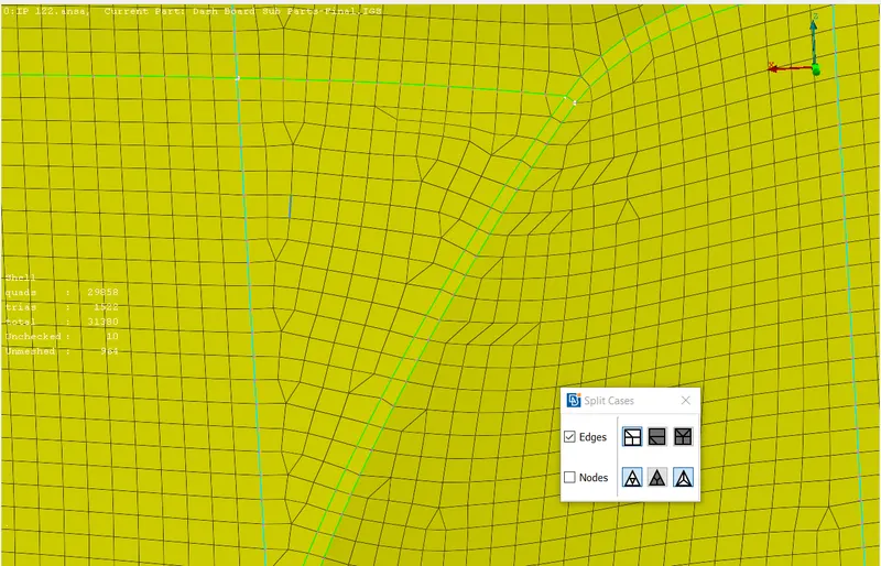
Select the smooth operation on that particular mesh region and where it will smooth the mesh properly.
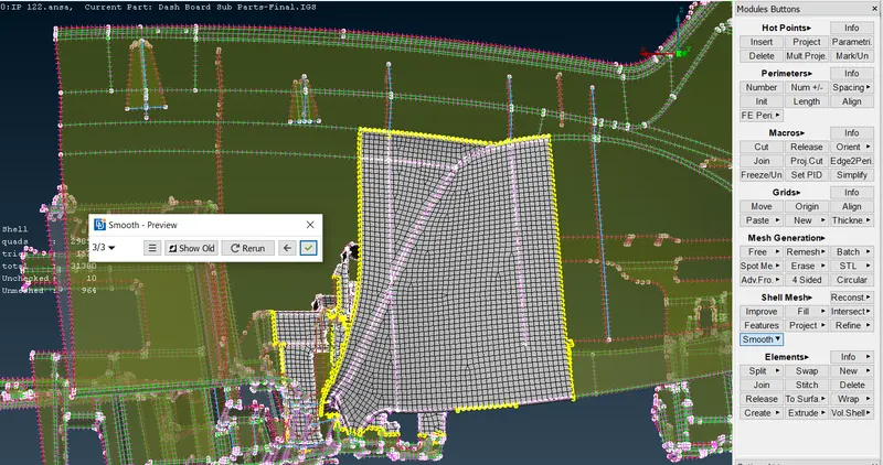
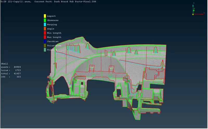
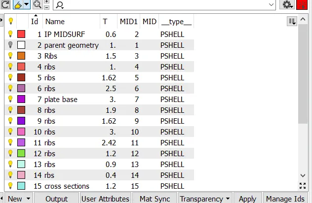
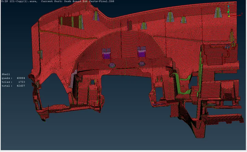
13.Assign the proper thickness to the varios midsurface properties and draw shell as a solid will show the thickness assign to the particular midsurfaces.
CONCLUSION;
- Performing geometry checks and geometry cleanup.
- Midsurface extraction of the different plastic components such ribs, doghouses.
- Avoiding the unwanted construction lines, fillets, which are falling below the minimum length criteria.
- capture features by satisfying the quality criteria.
- Meshing the mid-surface & Assigning thickness.
- Finally resolves all the quality issues in the FE model to obtain a good mesh flow.
Here below I'm attaching the link for the model.
https://drive.google.com/file/d/1JgaSWzcJTvFdt2IsHFAMY-BLBUkqjVsC/view?usp=sharing