Project 1 - 2D meshing on the instrumental Panel
https://drive.google.com/drive/folders/1zWL3rMJVzNYBtRcst7OJeqzTXvY1pRK4?usp=sharing
Aim: 2D meshing on the instrumental panel
Procedure:
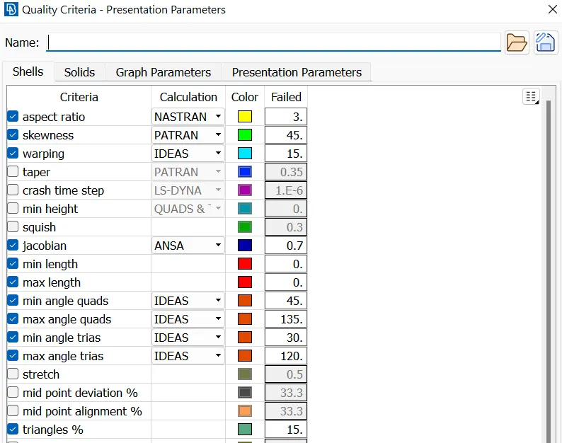
Given parameters
| S.No | Quality Criteria | Value |
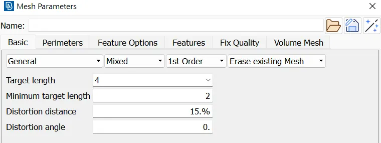
| 1 | Target length | 4 |
| 2 | Minimum length | 2 |
| 3 | Maximum length | 6 |
| 4 | Aspect | 3 |
| 5 | Warpage | 15 |
| 6 | Skewness | 45 |
| 7 | Jacobian | 0.7 |
| 8 | Minimum Quad Angle | 45 |
| 9 | Maximum Quad Angle | 135 |
| 10 | Minimum Tria Angle | 30 |
| 11 | Maximum Tira angle | 120 |
| 12 | Tria | 15 |
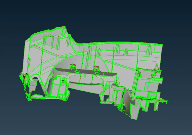
1. Import the model.
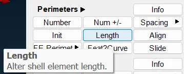
2. Give cons resolution to the model.
(Mesh module>Perimeters>Length)
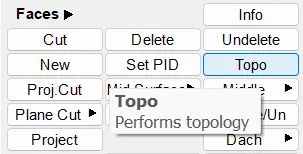
3. Give the topo to the model.
(Topo module>Faces>Topo)
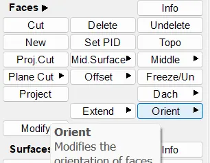
4. Give Orientation to the model.
(Topo>Faces>Orientation)
5. Now go for Geometric checkup.
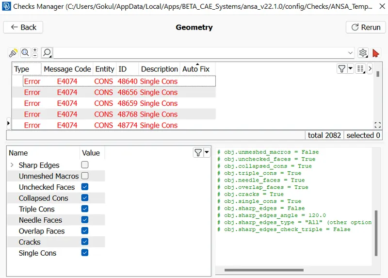
now you can see some errors in the Geometry, here we have to select all the errors and Fix them.
After fixing the errors automatically, if we still found the errors on the model, then we have to fix the errors manually.
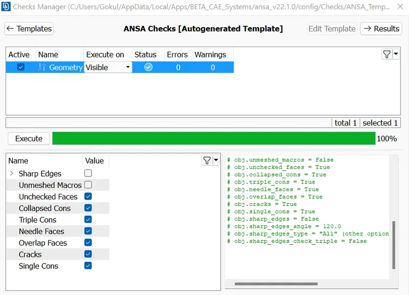
after fixing all the errors manually, we can see that it is perfect without any errors.
6. Now check the Thickness of the model to ensure whether the model is Plastic or sheet metal.
If the model has uniform thickness then it is a Sheet metal or if there is any variation in thickness then the model is Plastic.
7. There are various methods to extract the mid surface if it is a normal model then we can give offset, because the model is a complicated one we are using casting to extract the mid surface and use align manager.
8. Now the model is complicated so we use casting.
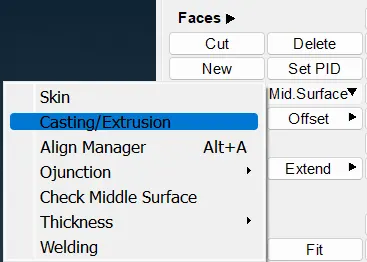
After giving casting to the model.
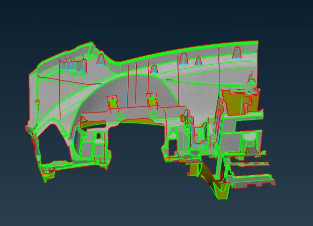
9. Give the Minimum thickness and Target element length.
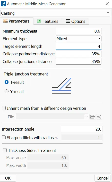
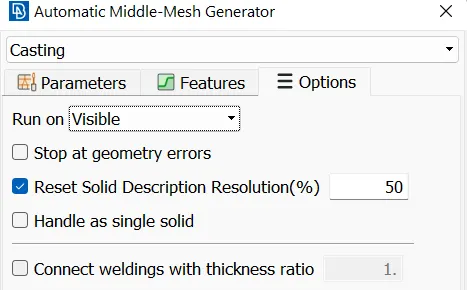
in the options unmark the Stop at geometry errors.
10. Give the Quality criteria and Mesh parameters.
Quality criteria:
Mesh parameters:
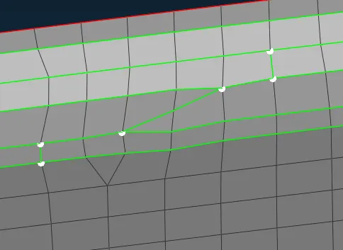
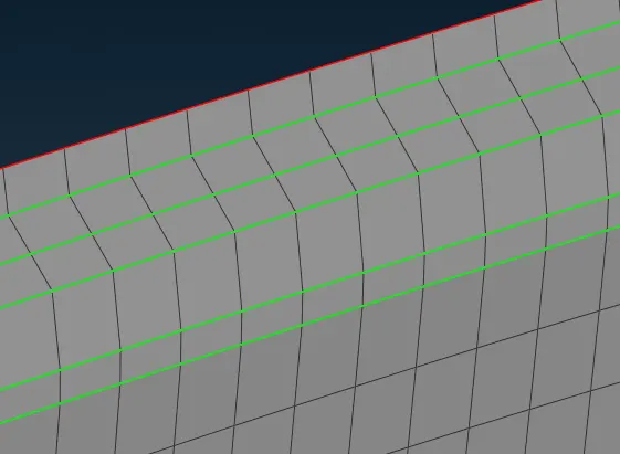
11. Remove the unnecessary construction lines.
Before:
After:
12. Here we can see that it does not capture properly and the mesh flow is also not proper, here we can use the align manager and fill option to get capture the dog house.
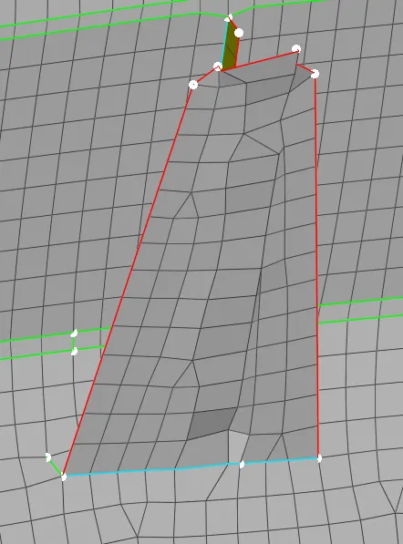
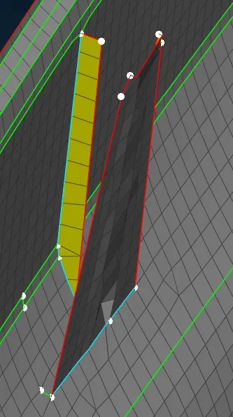
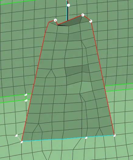
Using Align manager we can capture the surfaces.
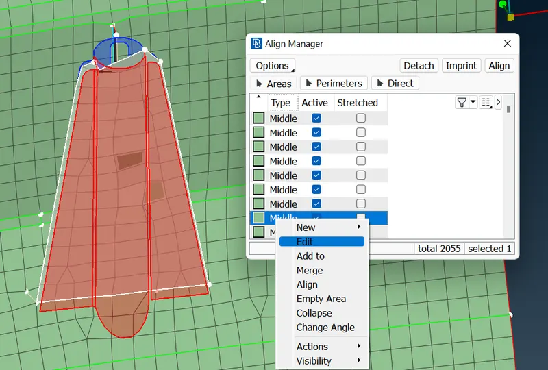
select both sides and give the middle mouse click
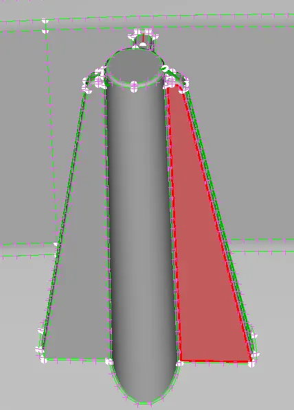
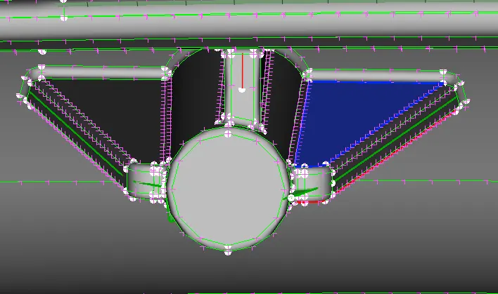
after giving the middle mouse click it been captured but the mesh flow is not proper
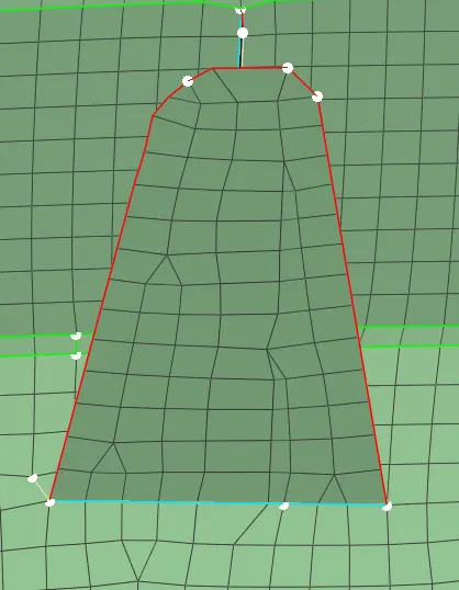
After this, we can improve the mesh flow using Reconstruction, Smooth and Split options giving a good mesh flow.
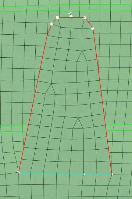
13. Here we can see the surface is missing, here we have to create the surface with proper mesh flow and definition.
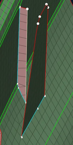
First, we project the perimeter to the other surface.
(Mesh module>Shell mesh>Project)
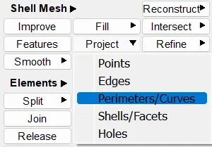
First select the shell where it has to be projected and then select the perimeter and give the middle mouse click, so the perimeters get projected.
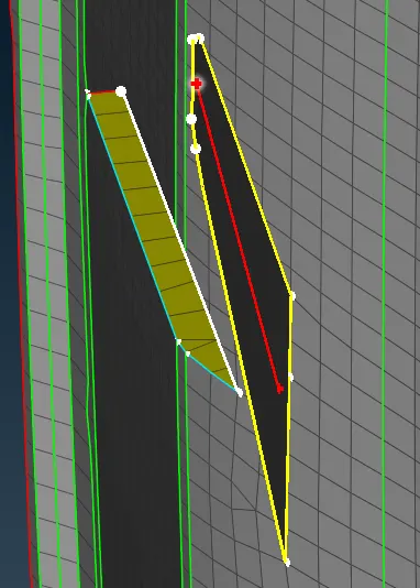
So here we can see the projection has been done here.
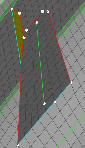
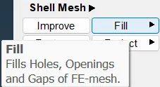
Now we can use the fill option and select the perimeters to create the missing surface.
(Mesh>Shell mesh>Fill)
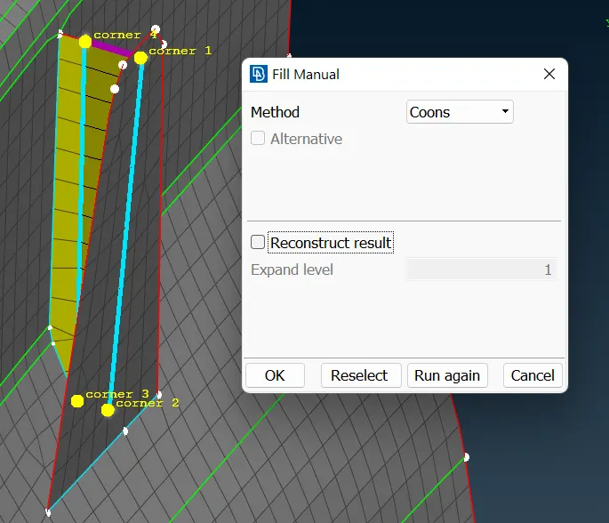
Selecting the perimeters and giving coons as the method and clicking ok.
So the entities have been created using the fill option.
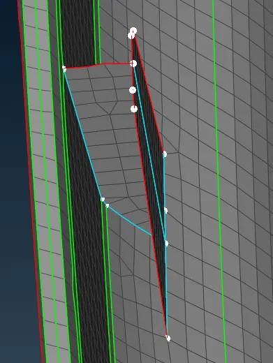
For better mesh flow use reconstruction smooth and split options.
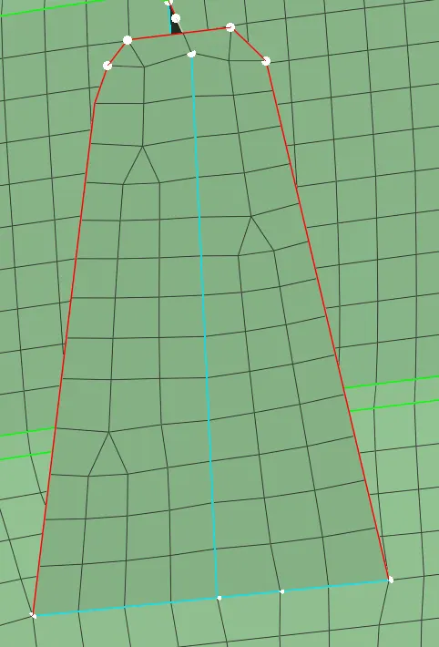
14. Here we can see the cross panel is not captured perfectly, here we can simply join the construction line, doing that somehow we can correct the error.
To join the lines (Mesh>Macros>Join)
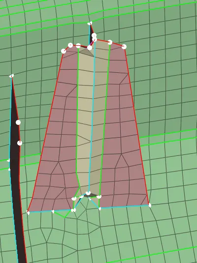
So here we can see that after joining the construction line we get better results.
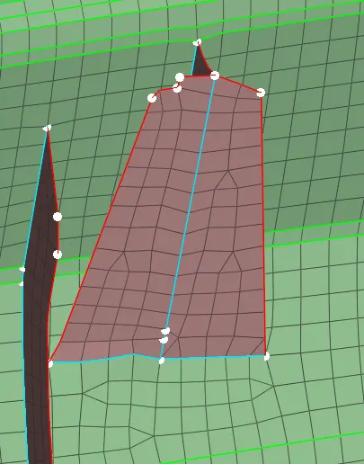
15. When we see the parent geometry here a panel is missing
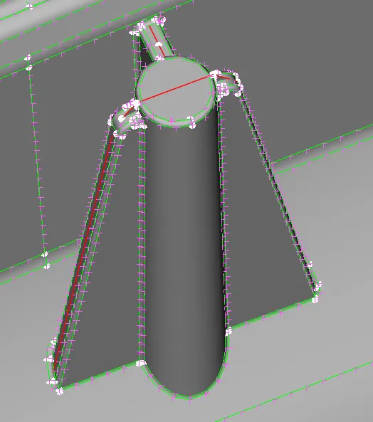
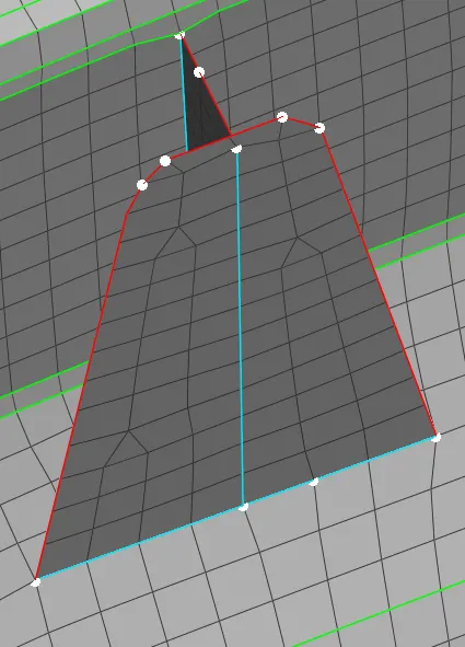
To create the missing entity we can use curves and create the entity with a fill option.
(Topo module>Curves>Create)
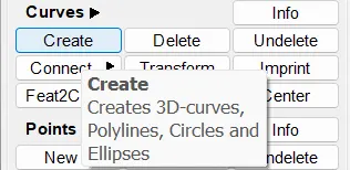
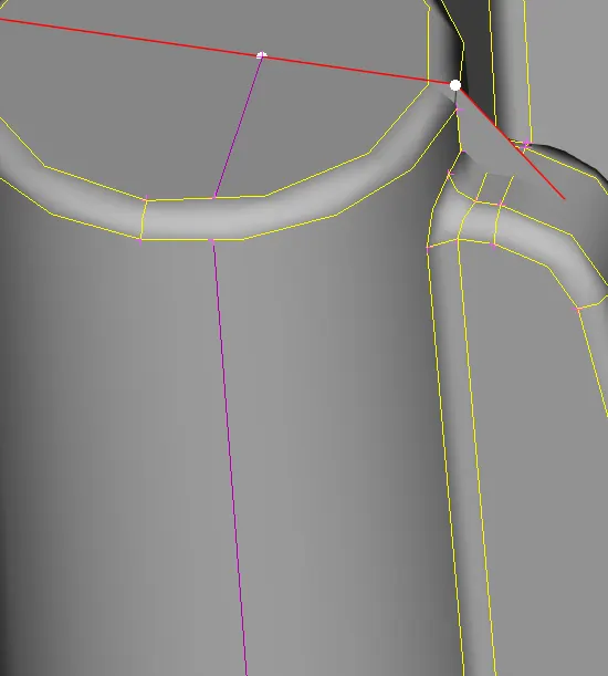
Using the fill option we selected the perimeters.
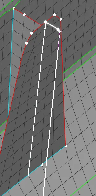
After applying the fill option.
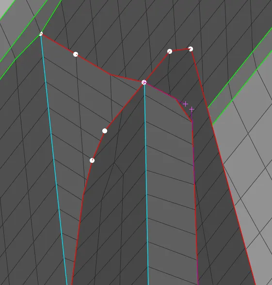
But at the bottom the entities are not connected to the surface, so we project the perimeter to the other surface and fill it.
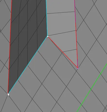
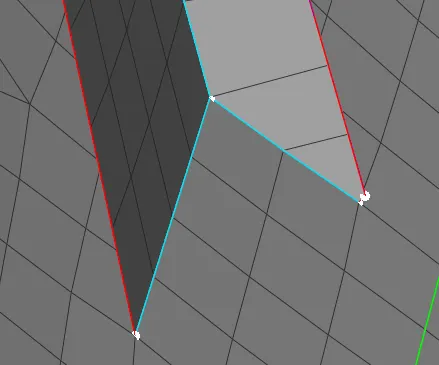
16. Now moving to the align manager we can see the newly created entity is empty.
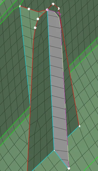
the same way we have to capture all the doghouses.
16. Now we have to check the quality failing and the mesh flow.
keep it in hidden mode so we can see the off elements.
in this situation use reconstruction and smooth options to reduce the off elements.
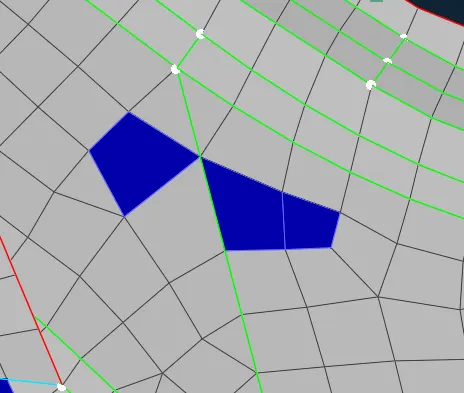
Make sure that the trias are not touching the construction lines and geometry lines.
Use the Split, Swap, and Paste options to reduce the trias and improve the mesh flow.

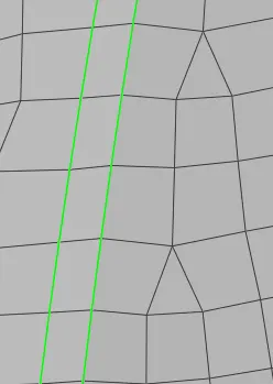
Trias facing each other can be removed using the Split option.
(Mesh module>Elements>Split or Swap)
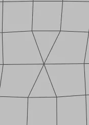
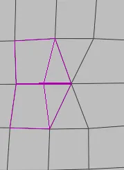
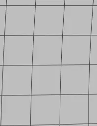
Trias Facing opposite can be removed using the Paste option.
(Mesh module>Grids>Paste)
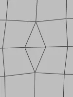
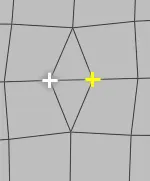
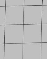
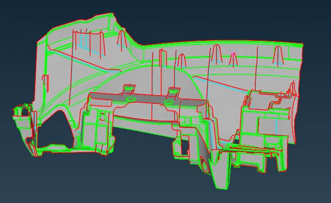
17. Finally give the thickness, reduce the off elements and improve the mesh flow.
Learning outcomes:
To correct the geometrical errors in different areas.
Manual mid surface in the complex components.
Giving good mesh flow.
Reducing maximum off elements and giving the quality mesh.
Result:
The 2d meshing for the given Instrumental panel model has been completed successfully.