Project 1 - 2D meshing on the instrumental Panel
Aim: 1. For the given component, check for the geometrical errors and mesh with the given element's Quality criteria. 2. Assign the thickness after meshing the component. 3. Prepare a detailed report on the approach for the challenge.
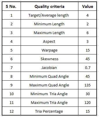
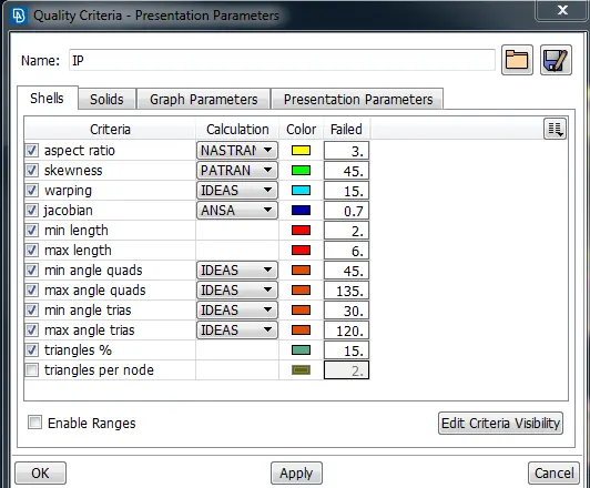
The quality criterion to be followed:
Abstract:
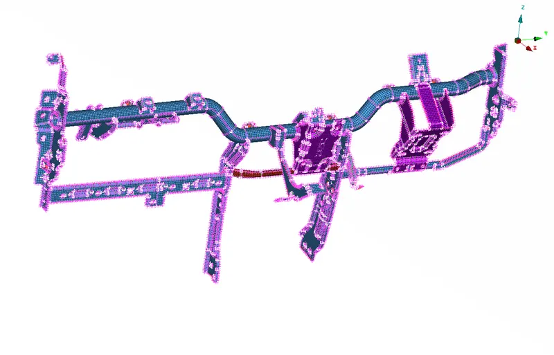
In this project, the instrument panel of the car dashboard is taken for the pre-processing stage of CAE. The pre-processing of this model is done using BETA-CAE-ANSA software. The mid-surface extraction and shell meshing are mainly demonstrated here in this project. CCB is a structural member located under the instrument panel fixed at both ends.
Procedure:
First, import the model to study the geometry.
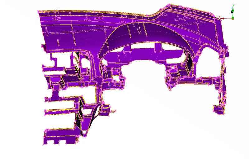
Fig. Image of Imported CAD model
Geometry cleanup
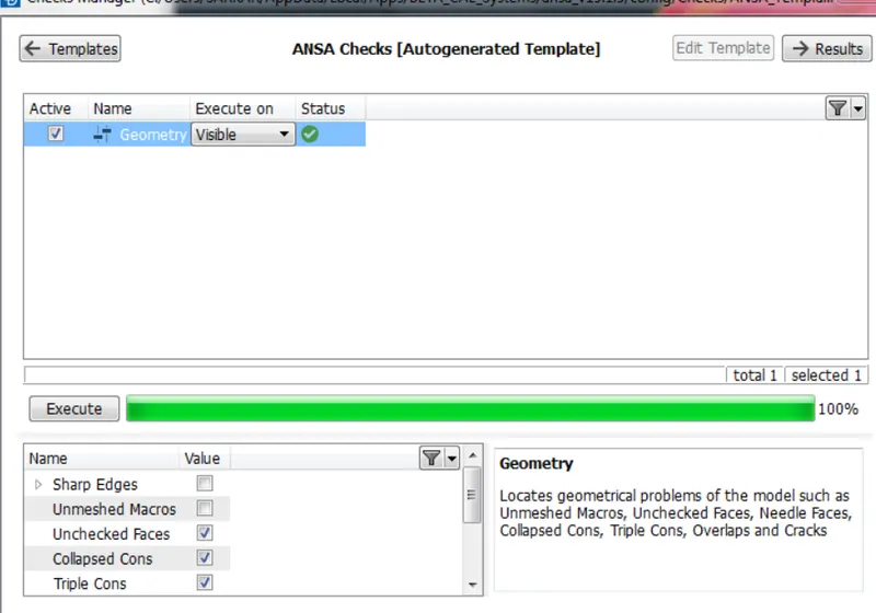
Once the geometry is imported into the ANSA environment, topological errors can be cleaned during the geometry checkup. After clicking the execute button, many errors will be visible. Before proceeding further these errors need to be fixed. There are two options that can be followed. Manual fixing of these errors one by one or by commanding ANSA to fix by itself. To fix the errors by the manual method a one by one approach needs to be adopted to fix it by either deleting the small redundant surface, releasing the triple cons, deleting hot points, repairing surfaces, etc. The hybrid option to minimize time consumption by auto-fixing most of the areas and rest manual fixing can also be used.
Uniform thickness is measured throughout the part. If changes in thickness are observed then all alike thickness needs to be kept under a separated property ID.
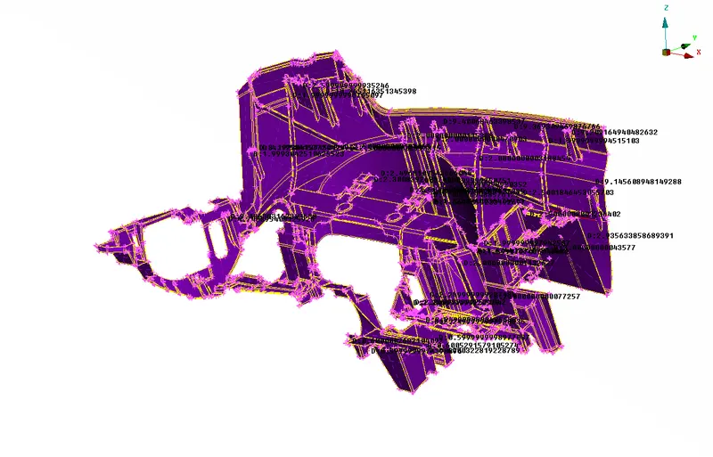
Fig. Image of Measurement of the thickness of the model all over the geometry
After measuring and storing data for thickness for sub-parts such as the main panel substrate, ribs, pillars, etc. can we extract the mid surface.
Orientation
The orientation needs to be checked thoroughly by the user every time while working on a model. All models should have the correct orientation as the orientation issue may cause somes issues at the time issue while merging the model with a complete vehicle. It is always preferred to maintain the continuity over the surface either grey or yellow throughout the face.
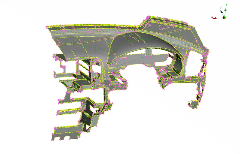
Fig. Image of Grey orientation continuity over the IP model
The two ways to extract midsurface:
1) Manual midsurface method
2) Auto midsurface method
Manual midsurface generation:
This can be done by manually selecting the surface and giving an offset option in the direction opposite to the grey surface.
Auto midsurface generation:
If the geometry is closed the the auto midsurface generation option is used. To avoid auto-deleting the parent geometry the following steps are followed: 1) Click on the mid surface tab under face 2) Select the entire geometry 3) Confirm the mid location
Here the manual offset method to extract midsurface is used as the surface thickness varies and ANSA is unable to segregate separated surfaces for auto midsurface generation.
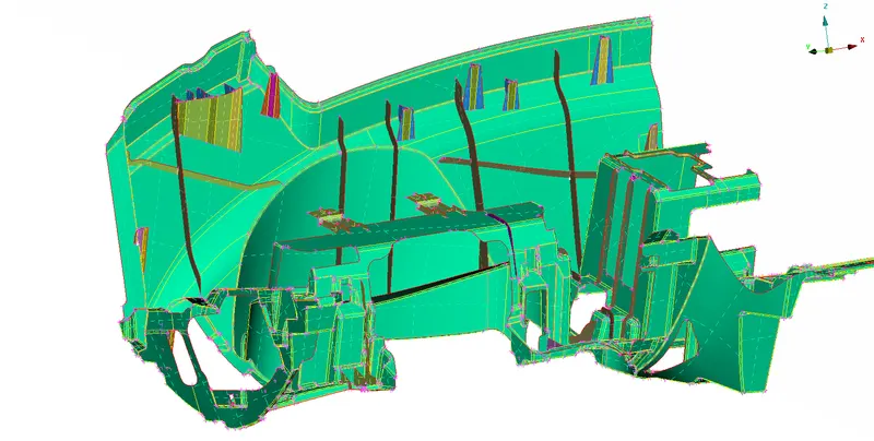
Fig. Image of midsurface extraction of the IP
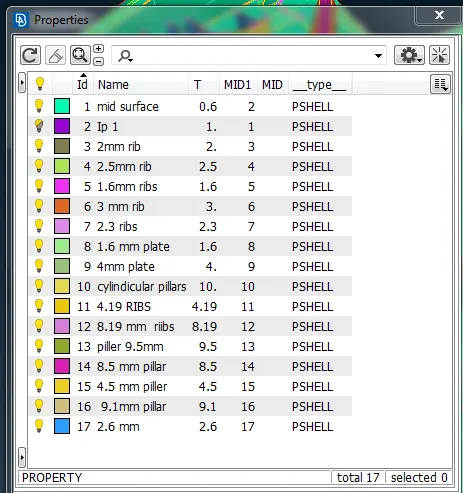
Fig. Image of Property ID with different thicknesses of the extracted midsurface
Quality Criterion Setup
To set up the quality criteria press the F11 key and check the boxes of the parameters of the required quality with the required values to be applied.
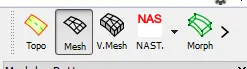
Meshing and Mesh improvement:
Change the mode from 'Topo' to 'Mesh' mode
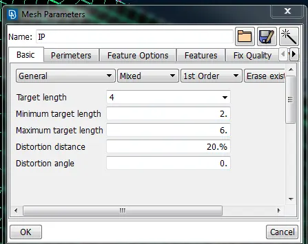
Before starting the mesh set the element length. Click the 'length' button under the 'parameters section'. Select the whole geometry and confirm. Then enter the value 5 and confirm. Do the same for the macros option. This alters the element length in the geometry by altering the no. of hot points at the periphery as well as at the macro areas.
Set the meshing parameters before proceeding to mesh
Meshed Results:
All the parts have been meshed as per the quality requirement and have good mesh flow.
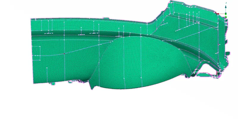
Fig. Image of Front view of the meshed IP
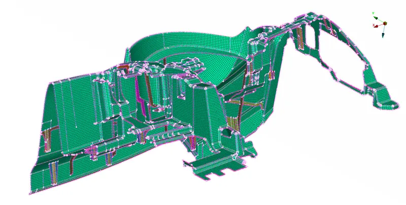
Fig. Image of isometric view of the meshed IP
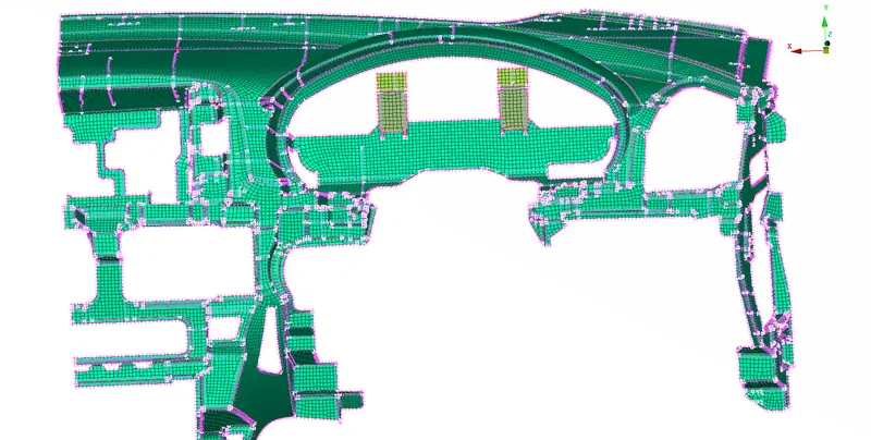
Fig. Image of Top view of the meshed IP
Image of features and failing elements
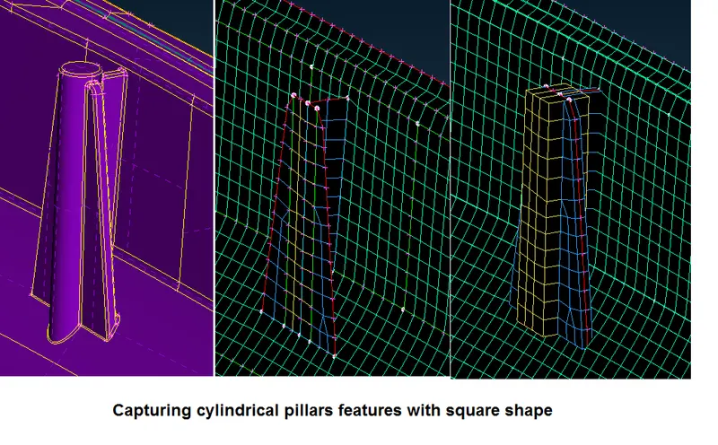
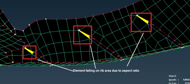
Fig. Image of Failing Rib areas
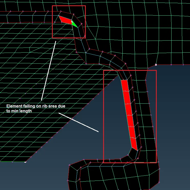
Fig. Image of min length failure near ribs
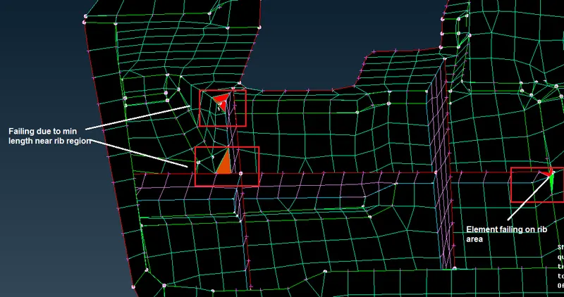
Fig. Image of Element failure seen near the rib region
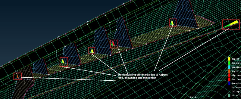
Fig. Image of Element failure seen near the extended rib region
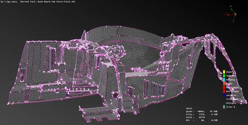
Fig. Image of Hidden mode view
Conclusion:
The panel has captured a good shell mesh. The total elements are 42716. 1750 are Tria elements. 40966 are Quads. The mesh flow is smooth nearer to the target length of 4 mm and is within the quality parameter. The above project was successfully completed as per the given requirement.