Project 1 - 2D meshing on the instrumental Panel
AIM:-
To perform 2-D meshing for the given Dash Board sub parts using ANSA.
PROCEDURE :-
The pre processing of the Dash board sub parts is done by using the following methodologies,
METHODOLOGY:-
- Import the model into ANSA GUI.
- Geometrical check for errors.
- Extraction of mid surface for the component.
- Assigning quality criteria and meshing.
- Set PID for Every feature and Assigning thickness.
STEP 1 - Import the model into ANSA.
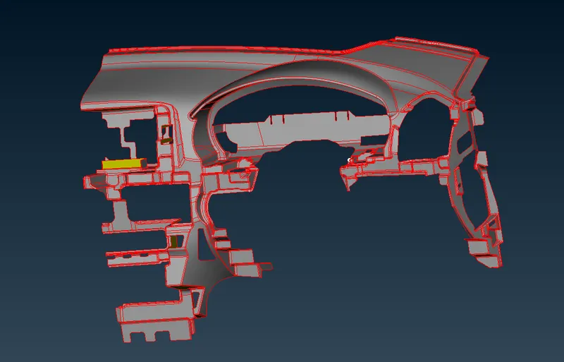
Fig -1 Import model
The first thing after importing the model is to go to MESH > PERIMETER > LENGTH > 1. This will improve the cons resolution of the model.
For an .IGS file imported there will be no connectivity in the geometry. So Select the FACES > TOPO option and click on the model (Box select) and middle mouse click. Now the Model will become a closed geometry.
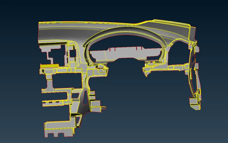
Fig -2 Cons resolution ,Topo, faces orientation changed to grey colour.
STEP -2 Geometrical check for errors
The model is now checked for geometry. Go to CHECKS MANAGER > GEOMETRY and select all the entities that are required and Give Execute.
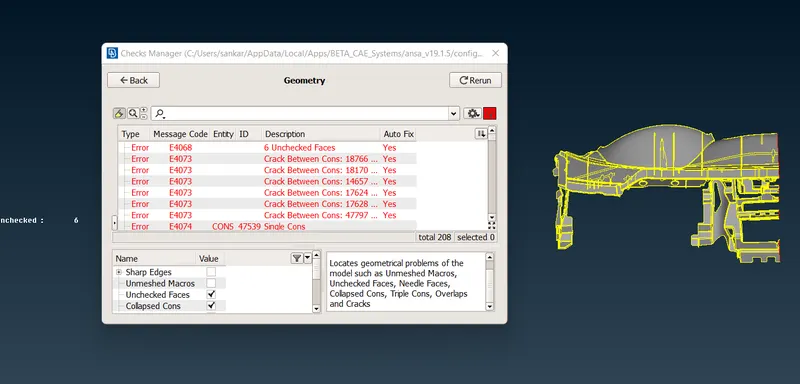
Fig - 3 Geometry errors that are visible.
For clearing the errors use CTRL+A and select all the errors and Right click on them and give Autofix. The errors that are remaining after autofix should be cleared manually. The following are some of the soving of errors discussed.
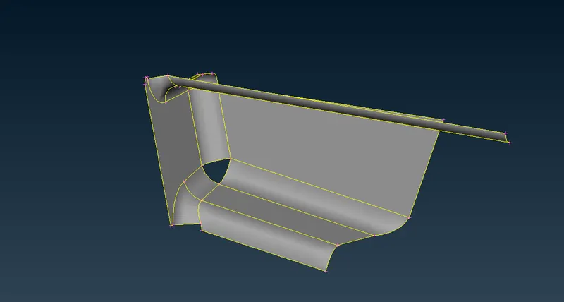
Fig -4 Unchecked Face error.
The above mentioned error is an unchecked face which shows the face is transparent. In case of clearing the unchecked faces please make a cut on the unchecke surface. After making a cut the surface will be visible. Now go to FACES > DELETE option and select the surface there and delete the unnecessary surface and create a new one with Fill hole option.
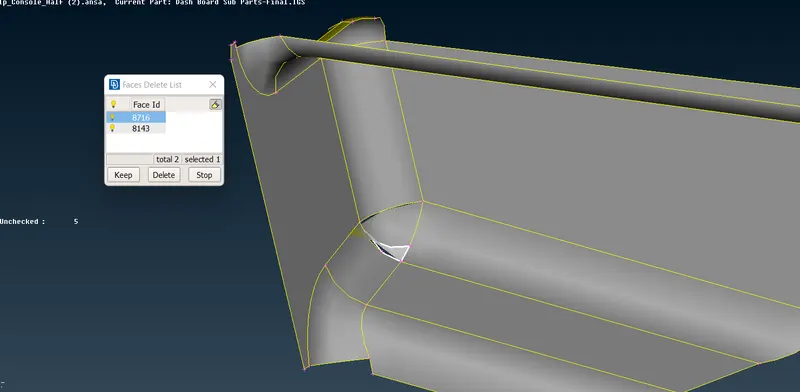
Fig -5 Deleting the unchecked surface.
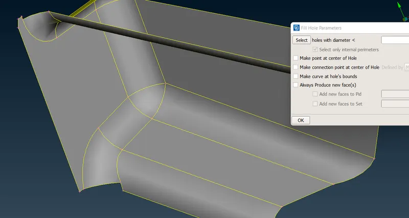
Fig -6 Using fill hole and getting the surface back.
The crack between cons error is also found in geometry and is solved by following.
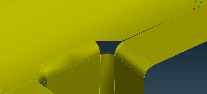
Fig -7 Crack between cons error
Similarly use FACES > DELETE option in TOPO Module and select the cracked cons there and delete them.
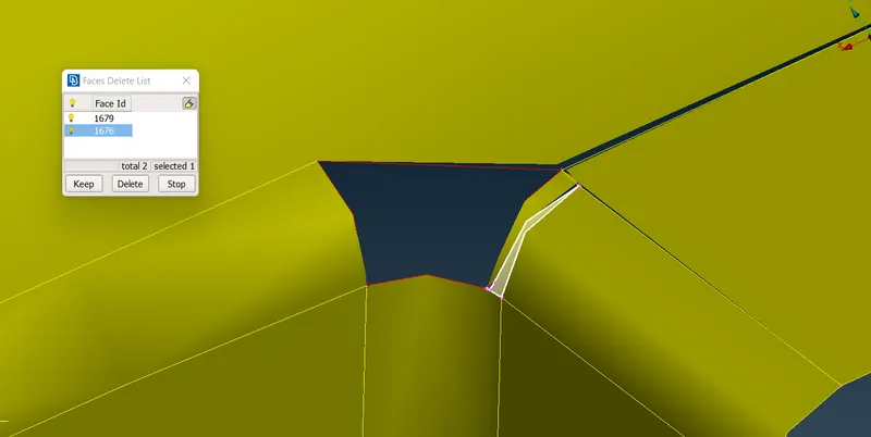
Fig -8 Deleting the cracked surfaces .
So delete both the surfaces ( needle like faces) and create a new surface over there by Fill Hole option.
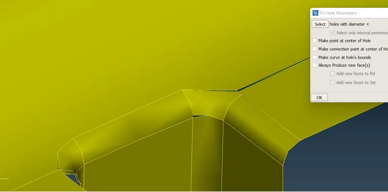
Fig -9 Surface created by fill hole.
Similarly the other areas where it is showing Unchecked faces and cracks between cons are worked on same manner and the errors are cleared.
After clearing the geometry mid surface is to be extracted.
STEP -3 Mid Surface Extraction.
Go to FACES > OFFSET and select the Feature option and click on the cross hatch on the surface where the features are not present.
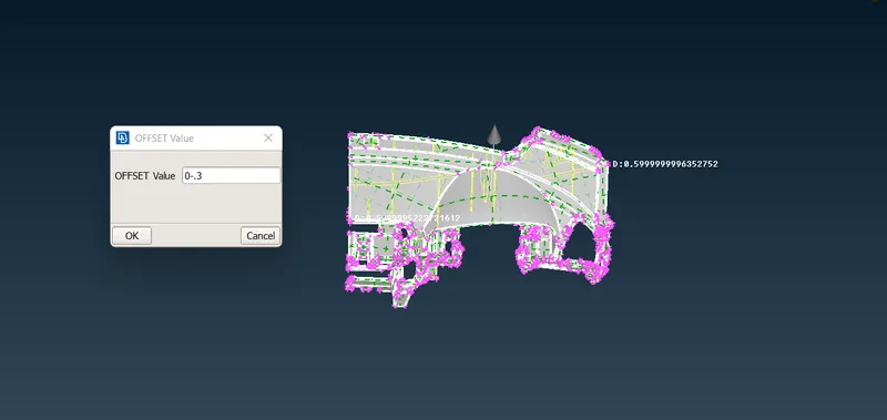
Fig - 10 Offsetting the parent
Measure Thickness in several regions and offset the face in case of uniform thickness.
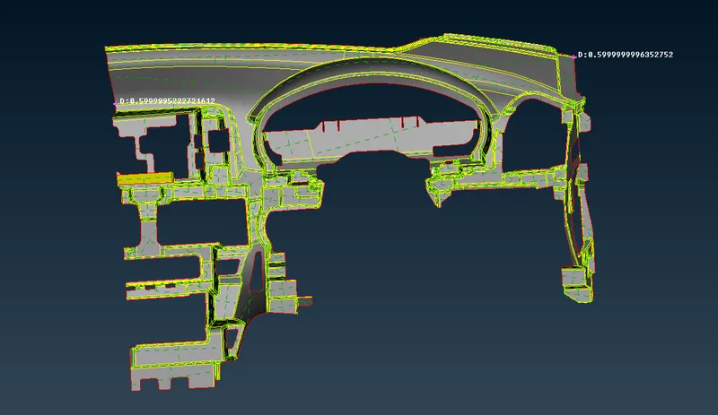
Fig -11 Mid surface extracted
After extracting the mid surface the area with features such as dog houses and ribs need to be created.the dog house is extracted below.
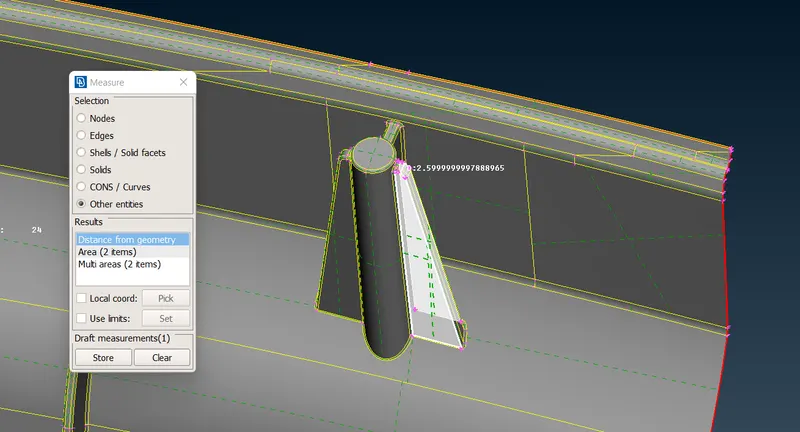
Fig -12 The thickness is checked for the attached Ribs and Faces > offset option is used.
similarlly, the other Ribs in different areas are extraced with offset option,if the thickness is uniform and are shown beloe.
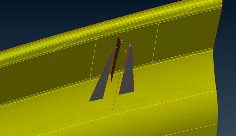
Fig -13 Creating curves for the dog house part and attaching the created one with the surfaces.
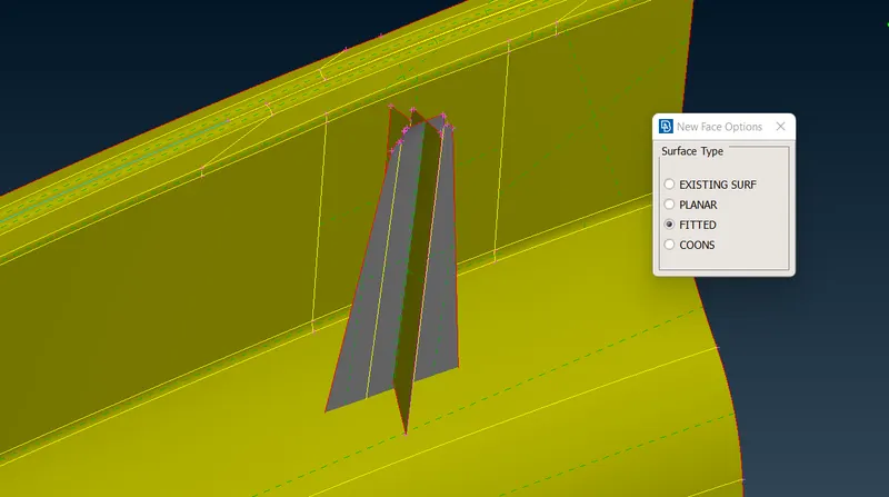
Fig -14 Creation of dog house surfaces.
After creating the Surfaces we need to check for intersection of the surface tp other faces.
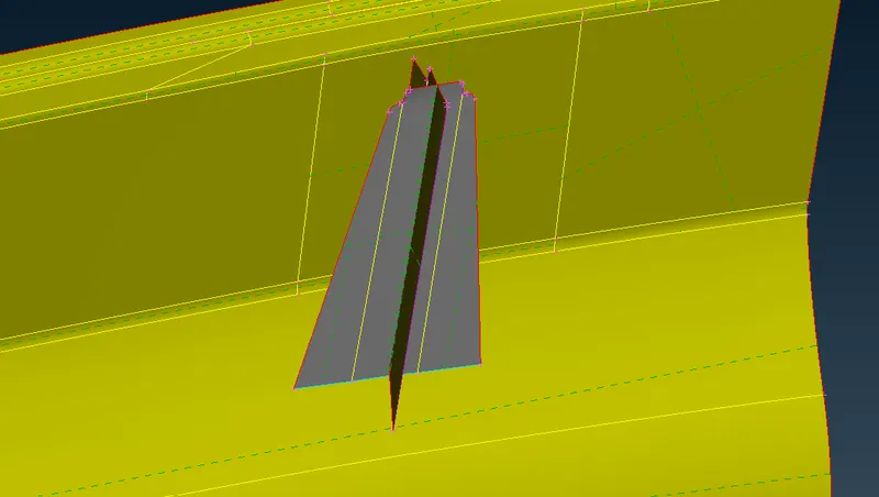
Fig -15 Intersection of Dog house ribs to the bottom face is completed.
Fig -16 Dog house created successfully and attached to the respective surface.
Similarly the features in the other areas also captured by following the above operation.
Here in the below areas the features are captured by OFF - Setting the faces at -0.5mm
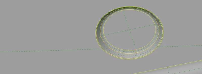
Fig -17 Features capturing
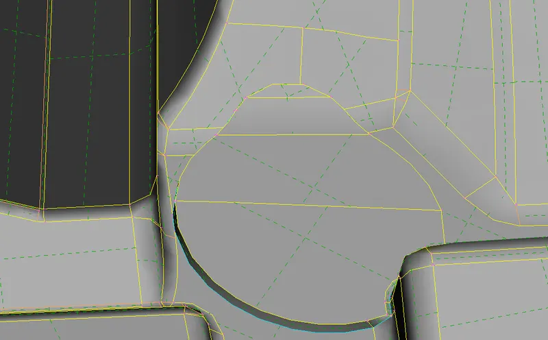
Fig -18 Feature captured by off-setting surface at 0.5mm thickness
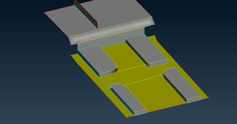
Fig -19 THe projected surfaces from the base are captured by off- setting as same with 0.5 mm
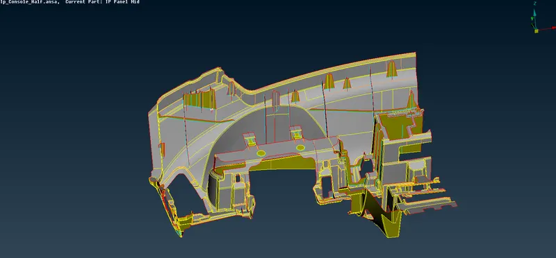
Fig -20 All the features in the Dashboard have been captured.
STEP - 4 Quality criteria and Meshing.
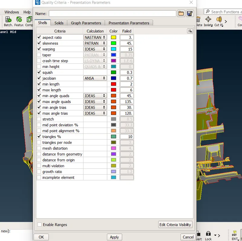
Fig -21 Applying quality criteria before meshing.
After applying the quality criteria we can start the meshing process. Here in this model Batch mesh process is followed.The following are the methods to perform batch meshing.
Go to MODEL BROWSER > Click on NEW > PART FROM VISIBLE and keep the mid surface only during this selection and give ok. The PID will be automatically Assigned.
Now go to Batch Mesh Manager MESHING SCENARIO > select the Content and choose file to do the Batch meshing by moving the file with the Green arrow present there.
Now go to Batch Mesh Manager and click on the DEFAULT SESSION > EDIT > QUALITY CRITERIA , MESH PARAMETERS.
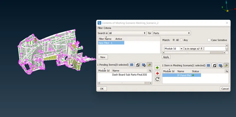
Fig -22 Batch meshing scenario
After selecting the scenario, click on the RUN option. The batch mesh will be generated.
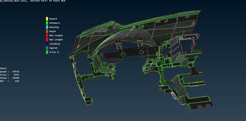
Fig -23 Batch mesh generated
After applying Batch mesh there will be a number of Off elments present. These off elemrnts should be reduced to less than 250 or below to ensure good quality of elements.
Step -5 Assigning separete PID and thickness.
The mid surface of all the sub parts of the Dash Board has been succssfully created. Now the thickness to Mid surface is assigned for every feature with respect to the thickness of the Geometry and separate PIDs are assigned for various thickness of parts.
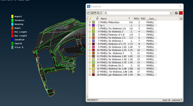
Fig -24 Assigning Thickness and PID.
The thickness has been successfully applied to all the Properties with respective to the parent and the assigned thickness of Midsurface is ccompared with the parent by Enabling Draw Shell as Solid in the presentation parameters.
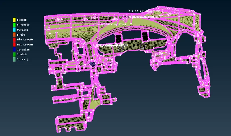
Fig -25 Applying Draw Shell as solid to compare MID surface with Parewnt geometry.
Result:-
The 2-D Meshing for the given Dash Board sub parts has been completed successfully and report is generated. There are OFF elements present in the areas of sharp edges and intrersection of Triplecons which was not possible to solve.The Following table shows the No.of Elements present in the model.
| Total no of quad elements | 41915 nos |
| Total no of Tria elements | 2227 nos |
| Total no of OFF Elements | 234 nos |
| Total no of elements present | 44142 nos |