Project 1 - 2D meshing on the instrumental Panel
Aim:
To Extract the mid surface and good mesh flow of given instrumental Panel within quality criteria.
Given Geometry:
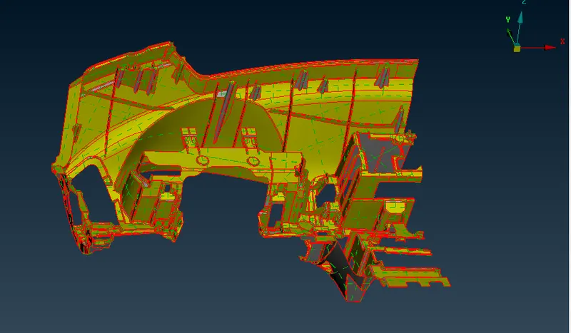
Givnen Quality Criteria:
|
S.No |
Quality Criteria |
Value |
|
1 |
Target/Average length |
4 |
|
2 |
Minimum Length |
2 |
|
3 |
Maximum Length |
6 |
|
4 |
Aspect |
3 |
|
5 |
Warpage |
15 |
|
6 |
Skewness |
45 |
|
7 |
Jacobian |
0.7 |
|
8 |
Minimum Quad Angle |
45 |
|
9 |
Maximum Quad Angle |
135 |
|
10 |
Minimum Tria Angle |
30 |
|
11 |
Maximum Tria Angle |
120 |
|
10 |
Tria Percentage |
15 |
Procedure:
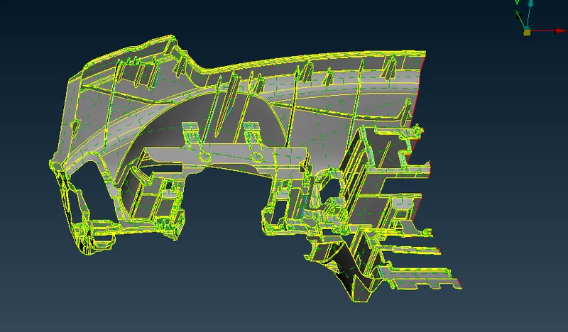
¬ First open ansa and import the geometry , after give topology to whole part.
¬ After give topology all edge are connected and create as a double cons.
¬ Then check the geometry and clear all triple cons , crack as well the errors.
After Topology:
Geometry check:
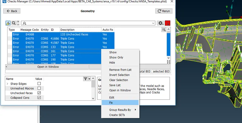
¬ Clear geometry errors using right click of error and there option fix click it it wil be clear.
¬ Some error will not able to clear using fix option ,that will clear manullly.
Create mid surface:
¬ Manual Method used to create mid surface of the components.
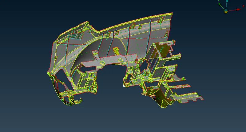
¬ Change the dog house
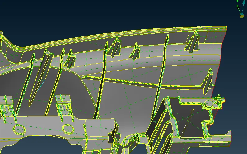
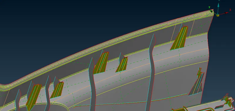
¬ Good mid surface taken for ribs .
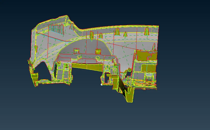
¬ After mid surface taken go to check geometry as usual and clear the geometry errors, single cons are neglected.
Meshing:
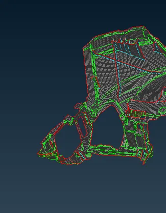
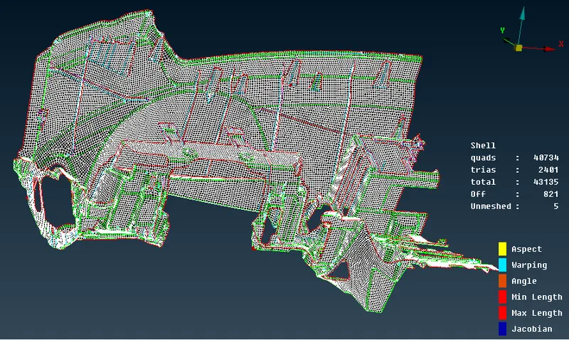
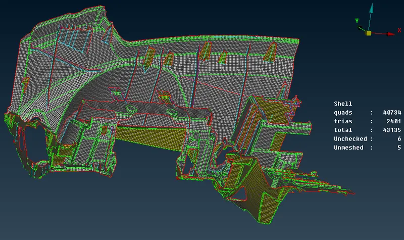
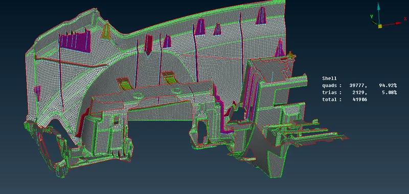
¬ Now go to meshing intially change the perimeter length taken as a given target length.
¬ Select the whole part and give as a perimeter length as 4 mm.
¬ After give target value set mesh parameter and quality critiria as given question.
¬ Strat mesh using Bset and spot mesh using to start meshing the components area by area.
¬ Are else using Baych mesh option to get good mesh and time save also to be.
Clear quality issues:
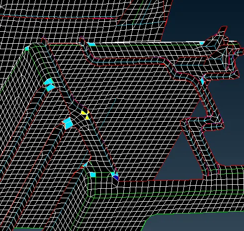
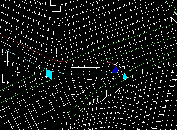
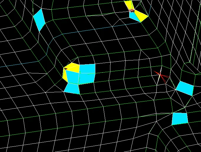
¬ Using Split, join and swap options are used to clear the mewsh quality manually.
¬ Then smooth options clear the warpage errors by adjusting the mesh elements.
¬ Then minimum lenghth errors clear by change the element size by remove or add the element.
¬There are lot of ways to clear the falied elments in the mesh of Jacobian, warpage skewness etc.
¬ After used these method and clear all the quality issues.
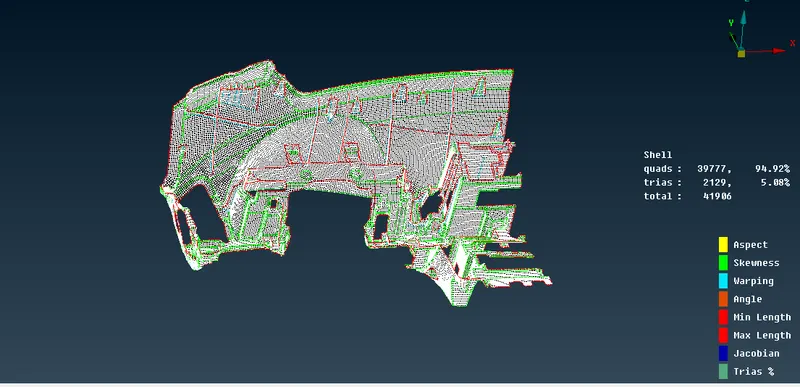
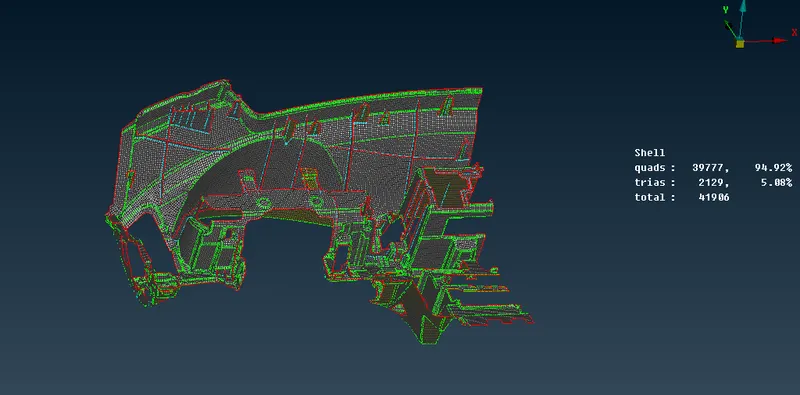
¬After completing the meshing to assign the thickness of the midsurface.
¬Then use set PID option apply the thickness by creating property ID.
¬ Select the main part set thickness value .
¬ Then Different thickness value assign the thickness using mesured option
SEt PID:
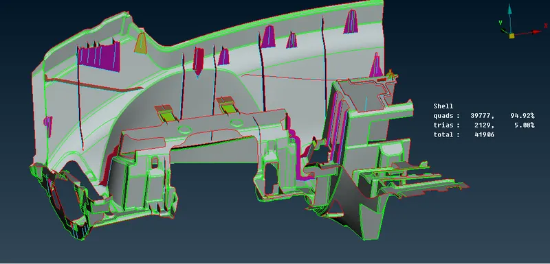
Assign the thickness:
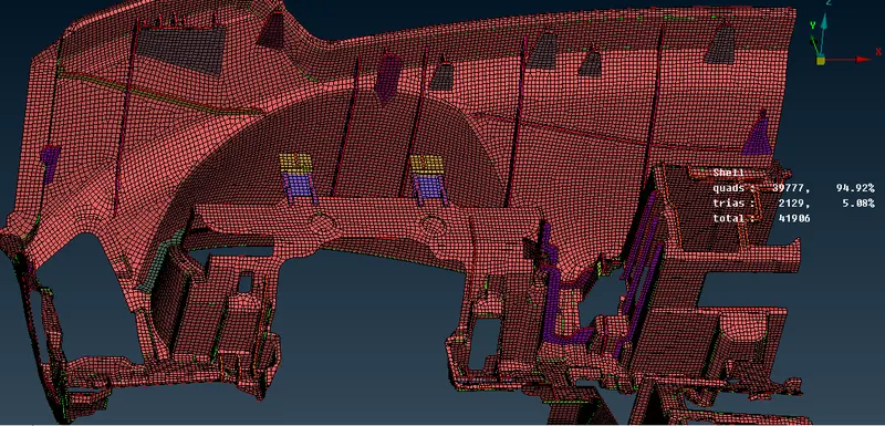
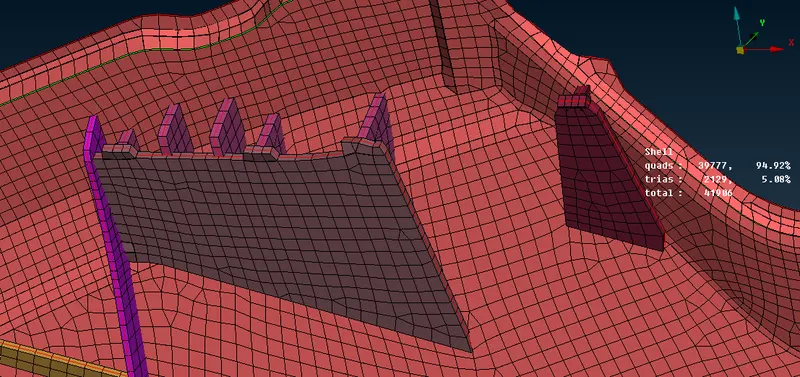
¬ After create PID go to quality parameter- presentation parameter and select Draw as shell as solid.
Learning Outcomes:
¬ Learn to create Mid surface for uniform thickness.
¬ Learn to take mid surface for ribs .
¬ Learn to take Automated midsurface.
¬Learn to mesh the model.
¬ Learn Batch mesh to model.
¬ Learn to clear off elements
Conclusion:
¬ The given components geometry check and cleared, mesh generated with the given quality criteria, After meshing different thickness to be assigned the given model sucessfuly.