Project 1 - 2D meshing on the instrumental Panel
AIM:
To try and perform mid-surfacing and meshing on the given model using the best method possible.
OBJECTIVE:
The given model has various features like ribs and dog-houses. Take midsurface of the model using different methods, different tools/options and mesh the component.
| Sr. No | Quality Criteria | Value |
| 1 | target/average length | 4 |
| 2 | Minimum length | 2 |
| 3 | Maximum length | 6 |
| 4 | Aspect | 3 |
| 5 | Warpage | 15 |
| 6 | Skewness | 45 |
| 7 | Jacobian | 0.7 |
| 8 | Minimum Quad angle | 45 |
| 9 | Maximum Quad angle | 135 |
| 10 | Minimum Tria angle | 30 |
| 1 | Maximum Tria angle | 120 |
| 12 | Tria percentage | 15 |
COMPONENT:
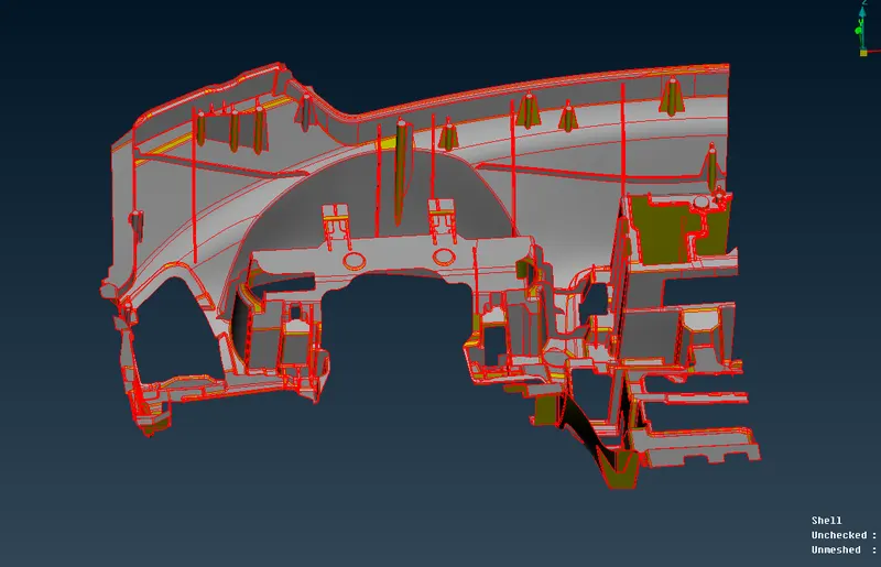
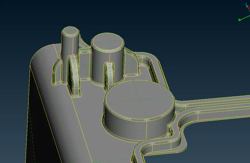
Given model upon opening in ANSA looked like this.
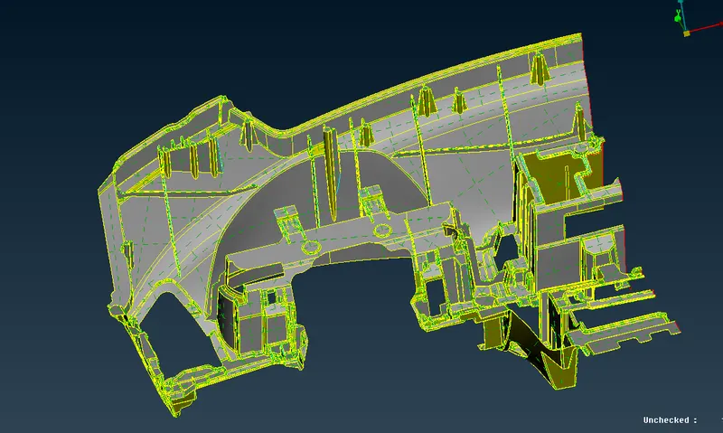
After performing Topo, model is stitched together.
PROCEDURE:
Geometry cleanup
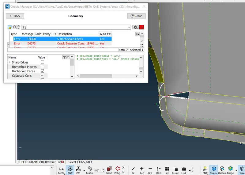
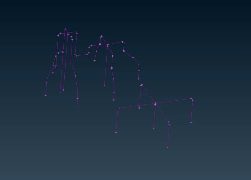
The gemoetrical errors in the model resulting from importing into ANSA should be checked using Checks->Geometry and they can fixed using Auto Fix. Many of the features/Cons lines that these parts have can be suppressed/removed without affecting the geometry, so that managing them and creating mid-surfacing will become easier.
2.Mid-surface generation
Faces->Offset (using feature selection), the base geometry of the model can be obtained in a single step.
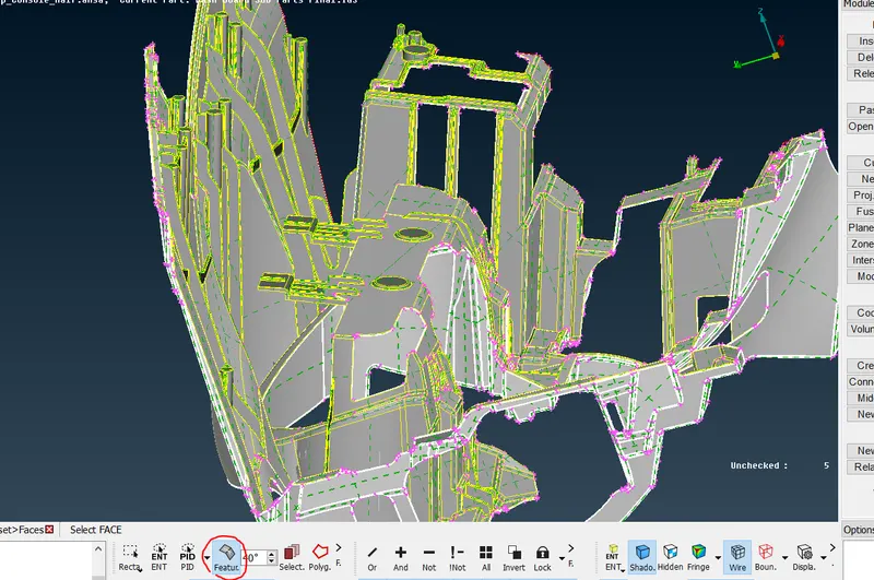
All other features like ribs and dog-houses' mid-surface is taken with the help of options like Curves->middle, Faces->New, middle, extend and intersect.
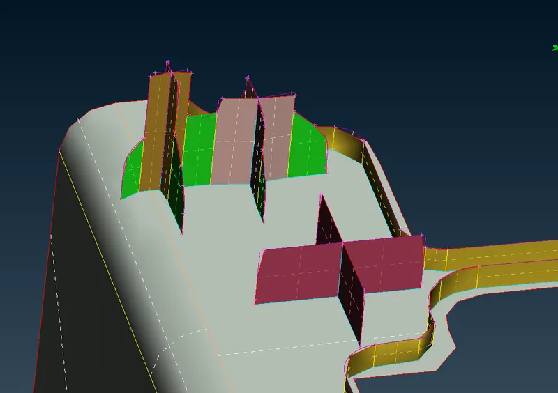
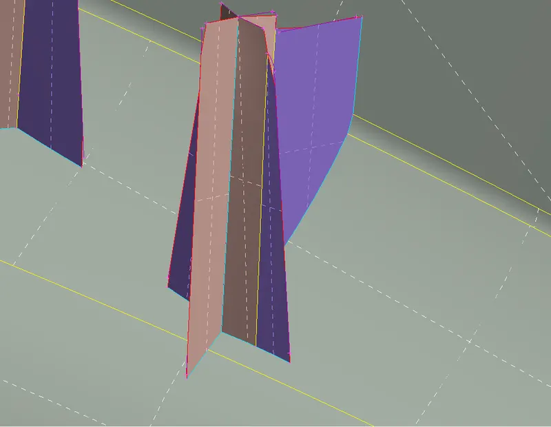
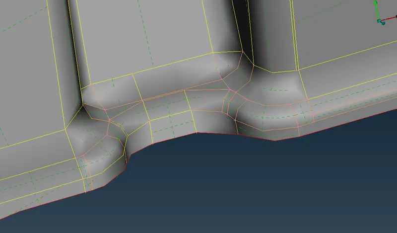
Many features along the fillet regions have distorted surfaces. These need to be cleaned using options faces->Delete and new.
Many additional CONS lines are present in the model which might create minimum length error for mesh. These can be supressed.
3. Measurement and assigning PIDs.
All the features in the model are not of constant thickness. These thickness are measured for various features and stored.
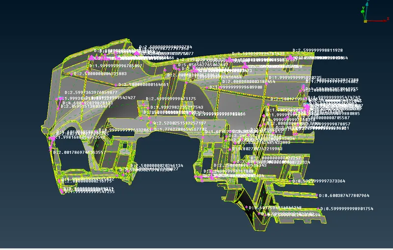
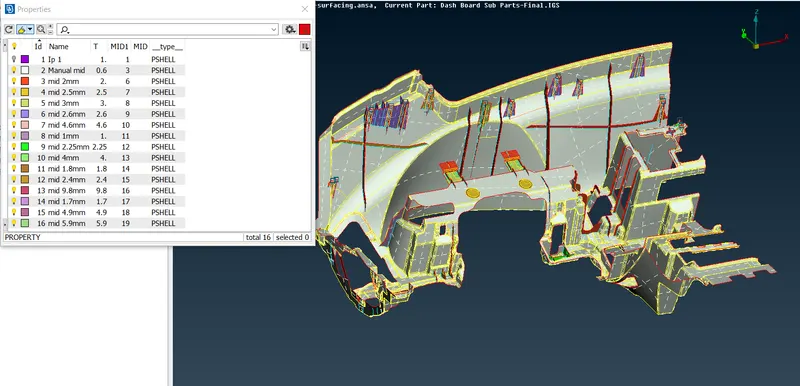
PIDs with these thickness are created and assigned manually to each macro region.
4. Meshing
For meshing, mesh parameters and quality parameters have been assigned using the given values.
Mesh is generated using Mesh Generation->Best. The elements failing quality criteria can be viewed using Auxiliaries->Hidden mode.
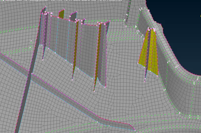
These faults can be rectified using options like Perimeters->Num+/-, Shell mesh->Reconstruct, Shell mesh->Smooth, Elements->Split, Macros->Cut, Hot points->Insert to reduce the number of OFF elements.
- The Triple CONS in the model resulting from various features makes it so that there are some OFF elements which cannot be removed unless further defeaturing of the model is done. So, as to not lose the features, those mesh elements have been left as it is.
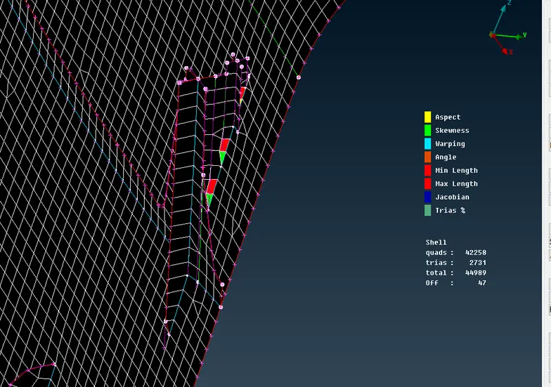
Meshed component:
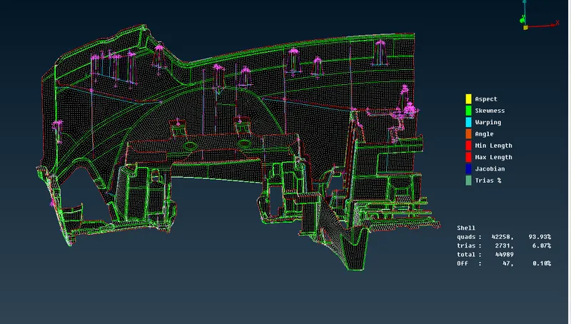
The tria percentage is well within the 15% limit. A total of 47 OFF elements were left out as they are unavoidable.
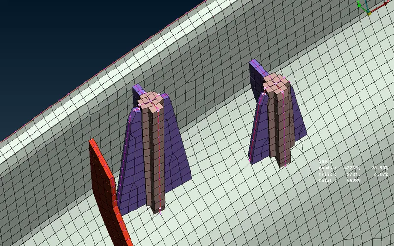
Using Draw shells as solid, the model can be compared to the original geometry.
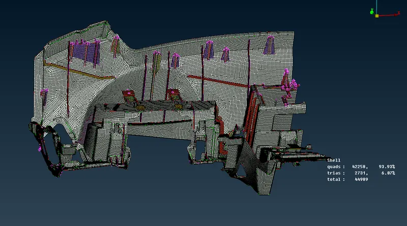
A closer look at the features gives an idea of the difference between original model and the mid-surface model.
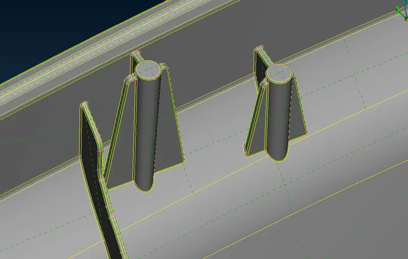
CONCLUSION:
The given component was meshed and improved as per the quality parameters by following the proper order of geometry cleanup, mid-surface generation, mesh generation and mesh improvements using right techniques suggested. The final model's target element length is under acceptable range. The OFF elements resulting from Triple CONS in the model have been left as it is, as further improvement leads to defeaturing of the model.
Link to the ansa file:
https://drive.google.com/file/d/1fhkaP5RFep1tPTUkU4mfxVvTxak61UpD/view?usp=sharing