Project 1
1)Buck CCM:
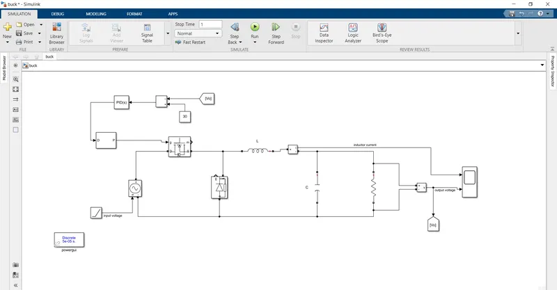
The buck converter is drawn in a the simulink model.The circuit is drawn with a mosfet and the inductor and capacitor along with a diode.
The duty ratio of the converter can be found from the input and the output voltage,
duty ratio,D=output voltage/input voltage
=30/40(Vi=40)
D=0.75
=30/50(Vi=50)
D=0.6
The switching frequency of the circuit fs can be=10kHz
To find the switching inductor we can use the formula,,
L=Voutfs⋅ΔIl(1-D)">Vout/fs⋅ΔIl(1−D)
The load resistance is obtained by,
R=V0^2/P
=30*30/500
=1.8 ohm
Inductor current,Il=V0/R
=30/1.8
=16.66 A
We can assume a 10% ripple in the circuit,
`Delta`Il=0.1*16.66
=1.66 A
L=(30/10*1.6)(1-0.7)
=0.5mH
The output capacitor value is found from the formula,
C=1-D8Lfs2(ΔV0V0)">1−D/8Lfs2(ΔV0/V0)
Δ">ΔΔV0=0.05*30=1.5V
C=(1-0.7)/(8*0.5m*10k^2*(1.5/30))
=1.5μ">μF
The feedback loop is made to maintain the output voltage.The result of the simulation will look like,
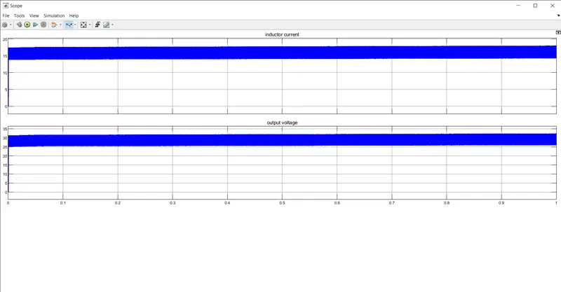
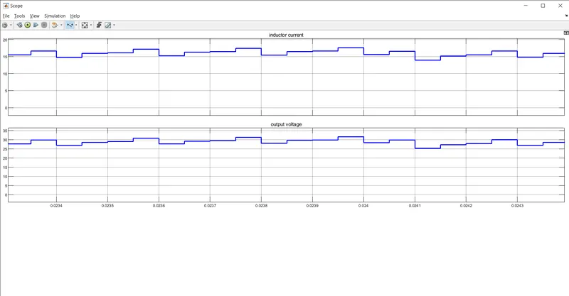
The zoomed out and zoomed in view of the output is shown above.The output voltage tends to remain 30 V.Due to the error in the pid tuner the voltage oscillates between 30 V.The inductor current also follows the value as we calculated.
2)Boost CCM:
The boost converter made with the mosfet and the diode in the simulink
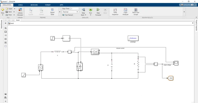
The input voltage is 20V-30V and the output voltage is 40V.The duty ratio of boost converter is ,
V0/Vi=1/(1-D)
D=-(Vi-Vo)/V0
=-(20-40)/40
=0.5
D=-(30-40)/40
=0.25
The load resistance is given by,
R=Vo^2/P
=40*40/600
=1.5 ohm.
inductor current,Il=Vi/((1-D)^2R)
=20/(1-0.5)^2*1.5
=53.33A
Inductor,L=(Vi/(fsIl))*D
=(20/(200k*53.33))*0.5
=0.9uH
Assume 10% ripple in output voltage,
capacitor,C=D/(Rfs(ΔV0/V0))
=0.5/(1.5*200k*0.1)
=3.33uF
The output of the simulation will look like,
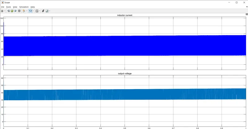
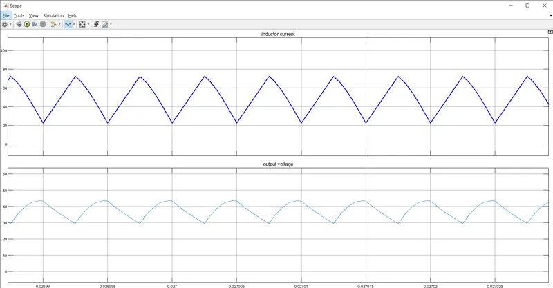
The zoomed in and the zoomed out graph of the output is shown above.The outptu voltage and the current follows the value as we calculated.The average outptu voltage is 40V.The input varies between 20-30V and the inductor current is of the order 50A.
10)Buck CCM:
The duty ratio of the converter can be found from the input and the output voltage,
duty ratio,D=output voltage/input voltage
=300/400(Vi=400)
D=0.75
=300/500(Vi=500)
D=0.6
The switching frequency of the circuit fs can be=10kHz
To find the switching inductor we can use the formula,,
L=Voutfs⋅ΔIl(1-D)">Vout/fs⋅ΔIl(1−D)
The load resistance is obtained by,
R=V0^2/P
=300*300/5000
=18 ohm
Inductor current,Il=V0/R
=300/18
=16.66 A
We can assume a 10% ripple in the circuit,
`Delta`Il=0.1*16.66
=1.66 A
L=(300/10*1.6)(1-0.7)
=5.6mH
The output capacitor value is found from the formula,
C=1-D/8Lfs2(ΔV0/V0)
Δ">ΔΔV0=0.05*300=15V
C=(1-0.7)/(8*5.6m*10k^2*(15/300))
=1.3μF
The output of the simulation will look like,
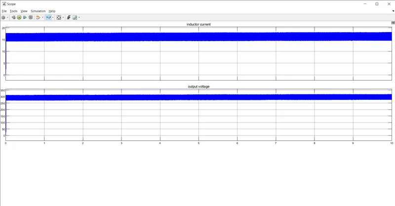
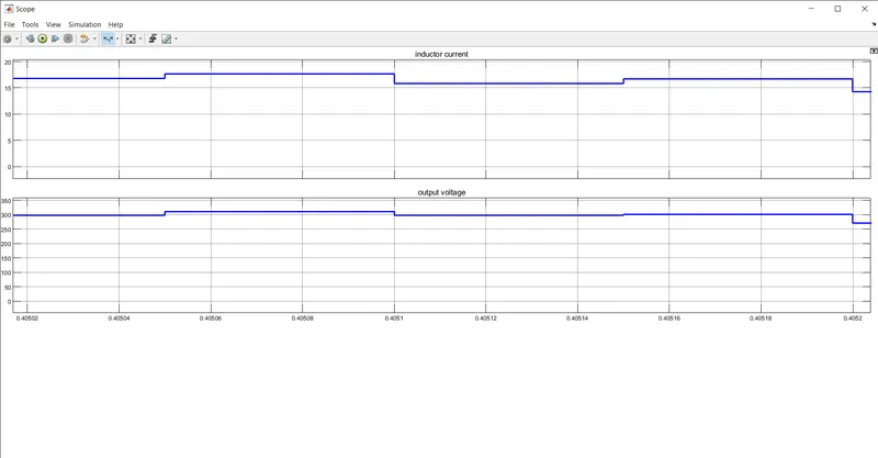
The zoomed out and the zoomed in version of the graph is shown above.The output voltage follows the 300V as per the calculation.The inductor curren talso follows the calculated value.