Project 1
AIM
Designing the wiring harness for the specified engine and creating a flattened view design in CATIA V5. By putting into practice the industry best practices covered in this course, such as the application of all packaging regulations in design. Apply protective coverings when necessary.
INTRODUCTION
A wire harness, which is also frequently called a wiring harness, is an external sheath that is used to protect specific kinds of electrical cables. The materials used to make wiring harnesses are often thermoset or thermoplastic, which can assist shield the cables from the elements.
The condensed wires, cables, terminals, and connectors that regulate an automobile's electrical system make up an engine wiring harness. Batteries, alternators, fuel injectors, fuses, audio systems, blower motors, fuel injectors, and computers are just a few of the parts it transmits power and control signals to. Wire harness manufacturers adapt it to each location, use case, and design it integrates with. It is also referred to as a cable harness, although it is more than just a grouping of interconnected wires. For the car to be safe, the wires must be protected. High temperatures, corrosive substances, and projectiles can damage wires, which can result in fires, braking problems, and serious malfunctions. Wires need to be covered and bundled in order to avoid these problems.
Install heat shield sleeves or wiring insulation made of flameproof material that can tolerate direct contact with hot surfaces. It must be made of a material designed especially for use in automotive under-hood applications and able to tolerate continuous temperatures of up to 125°C (257°F). The wires in a car's harness can be protected in a variety of ways. Although they firmly bind wire together, zip ties don't provide much insulation or safety. Plastic conduits are less flexible than other materials and can increase weight, but they provide protection against uneven surfaces. Heat-shrink tubing offers defence against chemicals, heat, and moisture. The application takes a lot of time, though. Another tool for securing and bundling cables is tape. Because they can be used for protective wrapping, bundling, and sealing, tapes are more versatile and economical than other bundling solutions. Tape can provide abrasion protection, electrical and thermal insulation, and sound absorption with the same quality as other ways because it comes with a large selection of backings and adhesives. In addition, compared to tubing or plastic conduit, tapes are lighter, more flexible, and simpler to use.
OBJECTIVE
- Define all the mechanical connectors electrically and save it in the Catalogue.
- On the provided engine 3D CAD model, arrange all of the connectors in the necessary locations.
- In accordance with the packing guidelines, position P-Clamps and Fir Tree clips in the appropriate locations.
- Create the wiring harness routing using all mounting hardware and electrically defined connectors.
- In order to generate subbranches and link to different connections in the geometrical bundle, create branching points at the necessary locations.
- Use protective coverings where necessary.
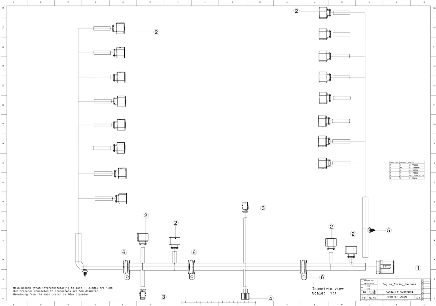
- Construct the wiring harness flattening for the bundle.
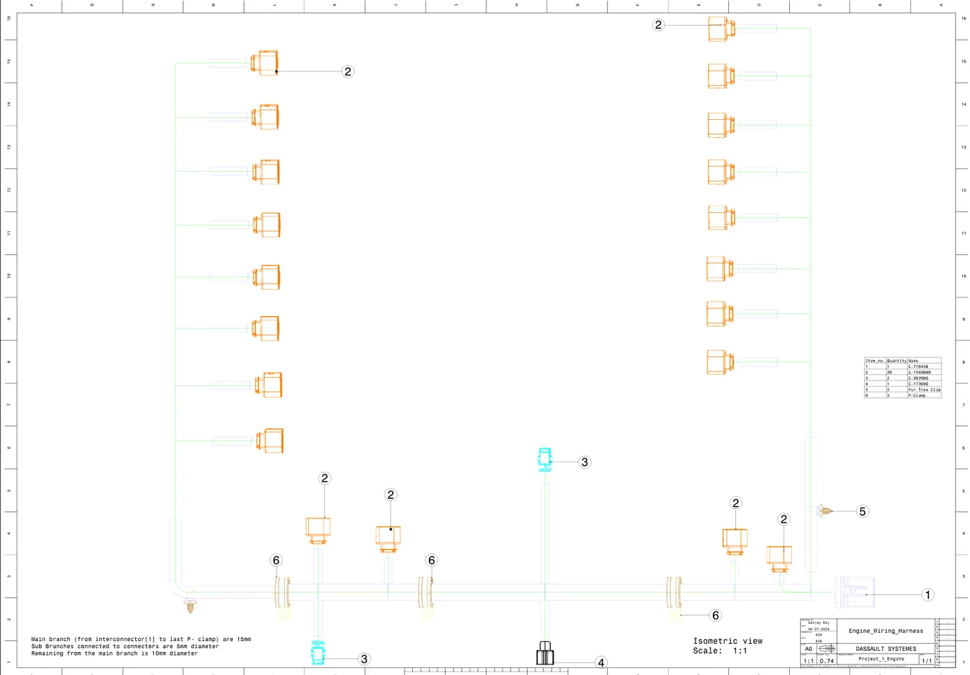
- Using the drafting workbench, create a drawing sheet with the flattened wiring harness.
PROCEDURE
Step 1
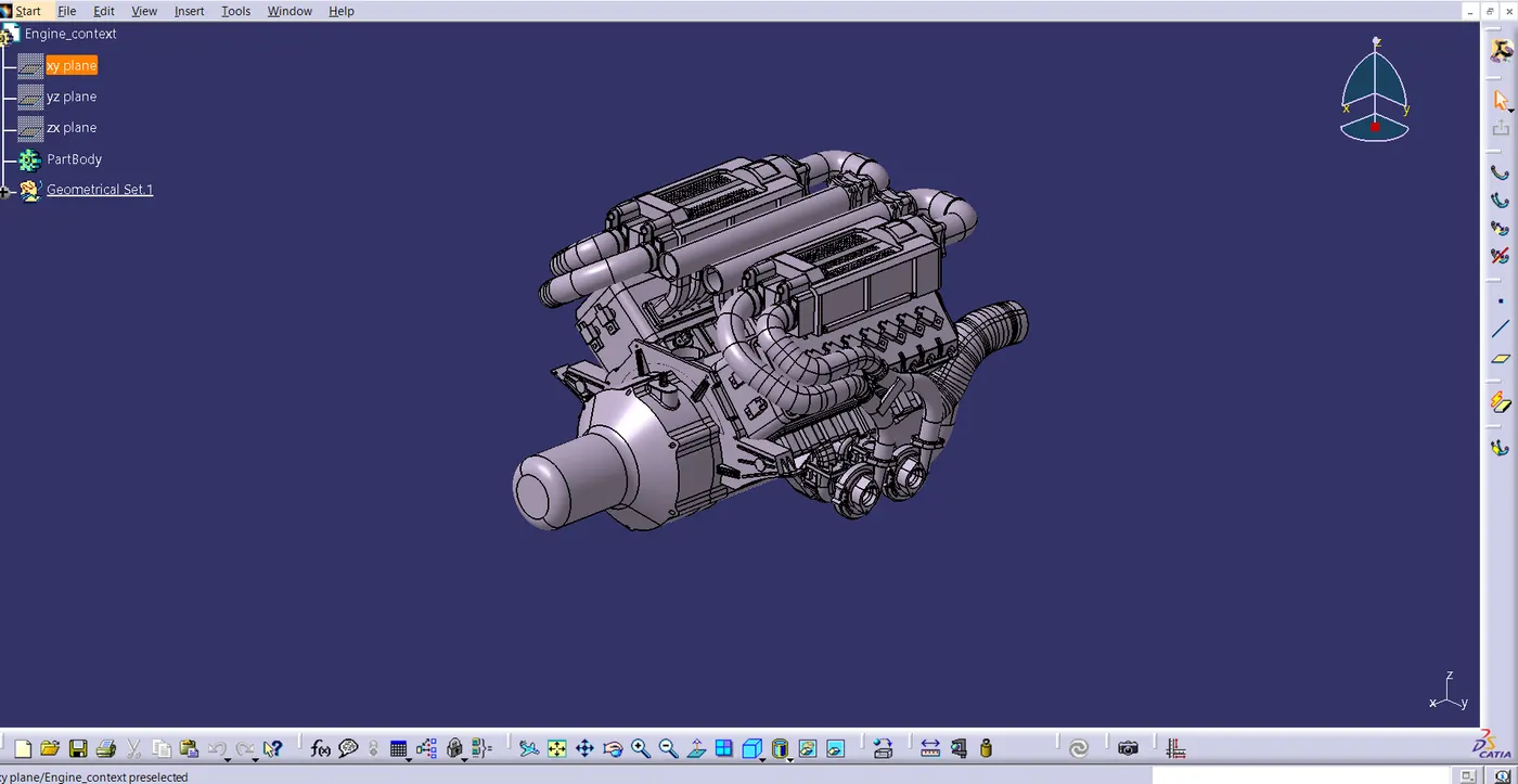
- Download the engine CAD data and required connectors CAD download the engine CAD data and required connectors CAD data from the given source.
Step 2
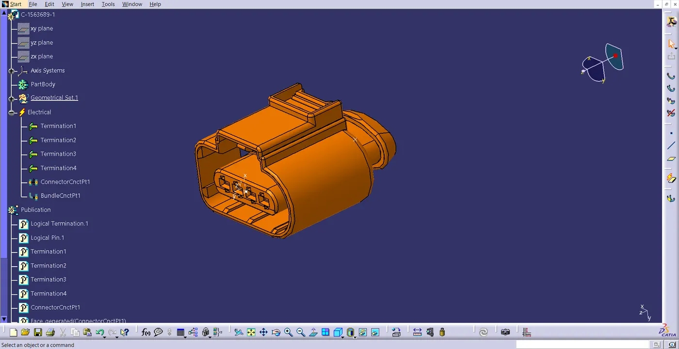
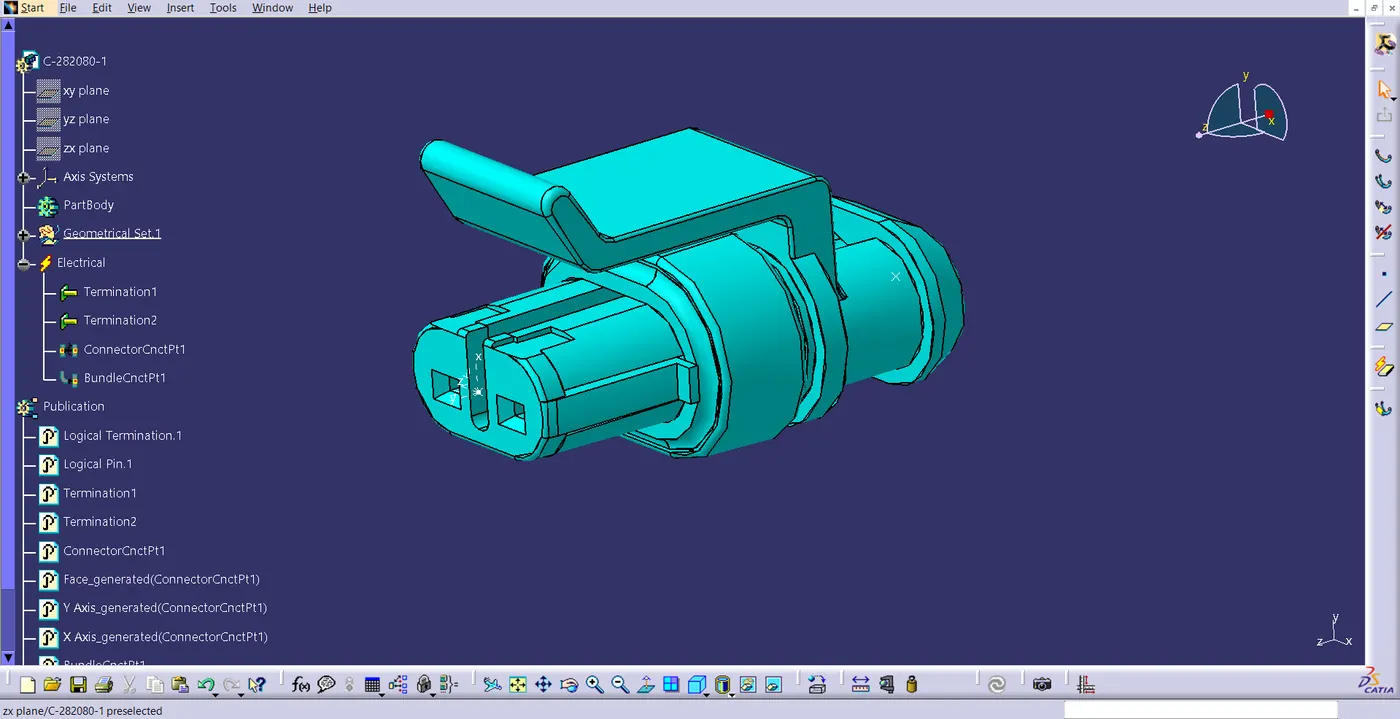
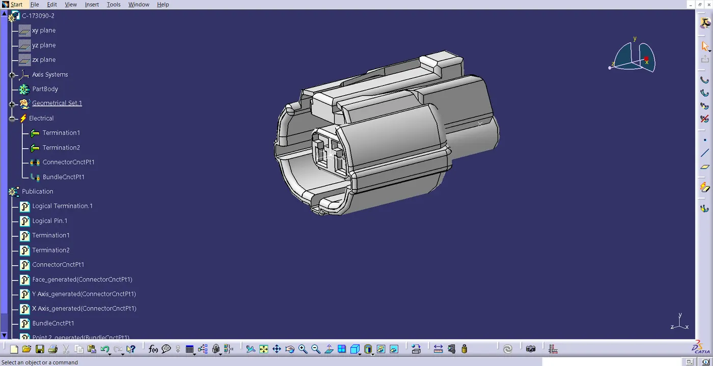
- Download the necessary connectors from the source, then use the electrical component design work bench to convert the mechanical connectors to electrical connections by following the steps listed below.
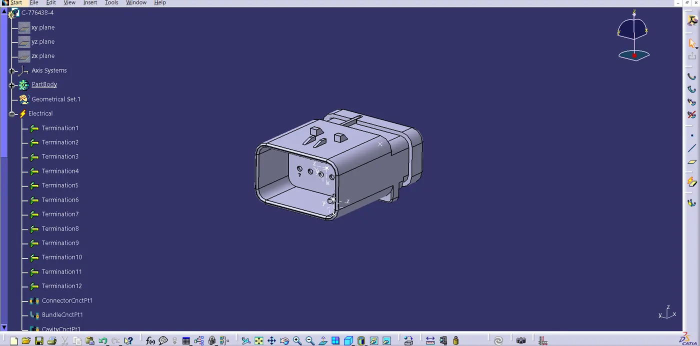
- Enter the mechanical component workbench and establish the necessary geometric parameters. On the necessary sides of the CAD part, create connector and bundle connection points.
- Establish an axis system on the connector connection point with the Z coordinate, the X coordinate facing the locking mechanism, and the Y coordinate normal to the connector face.
- Create cavity connection point for connectors having the cavity for mounting clips with the developed geometrical parameters.
- Define part as electrical connector.
- Define the connection point for bundles.
- Determine the connector's connection point.
- Determine the cavity's connection point.
Step 3
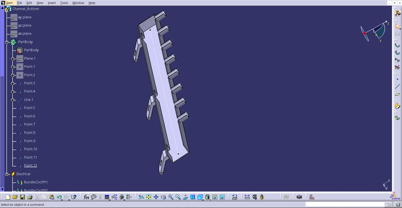
- The process by which the Channel is electrically defined.
- Make entrance and exit points for the package.
- Use the external curve inside the channel to draw a line curve connecting the primary entry and exit points to create a multi-branchable structure.
- On the holes where the injector connections are to be connected, create eight bundle entrance points.
- Use the define mounting equipment option to define the channel electrical using the geometrical criteria.
- Utilizing the "define bundle connection point option," create define bundle entry points.
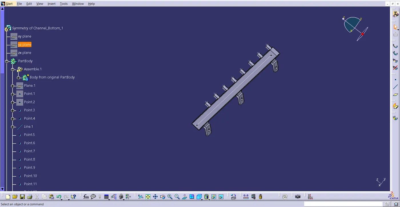
- After that, make a new product assembly with a channel assembly for the top and bottom parts.
- Create a channel symmetrical assembly. Using the define mounting equipment option, define the symmetry bottom channel electrically. Create all necessary geometrical parameters on it.
Step 4
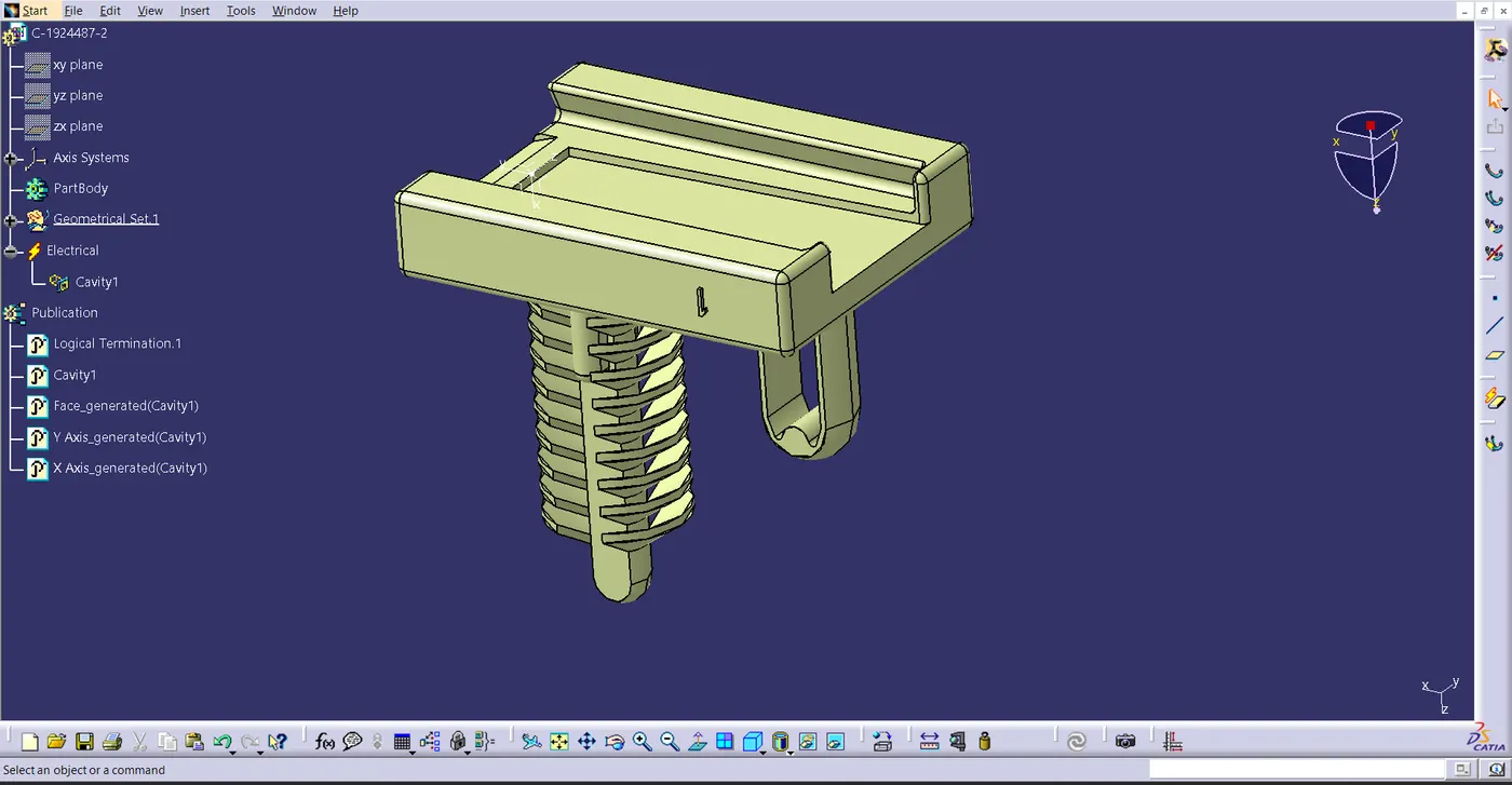
- Download the required clamps and clips.
- Define them electrically.
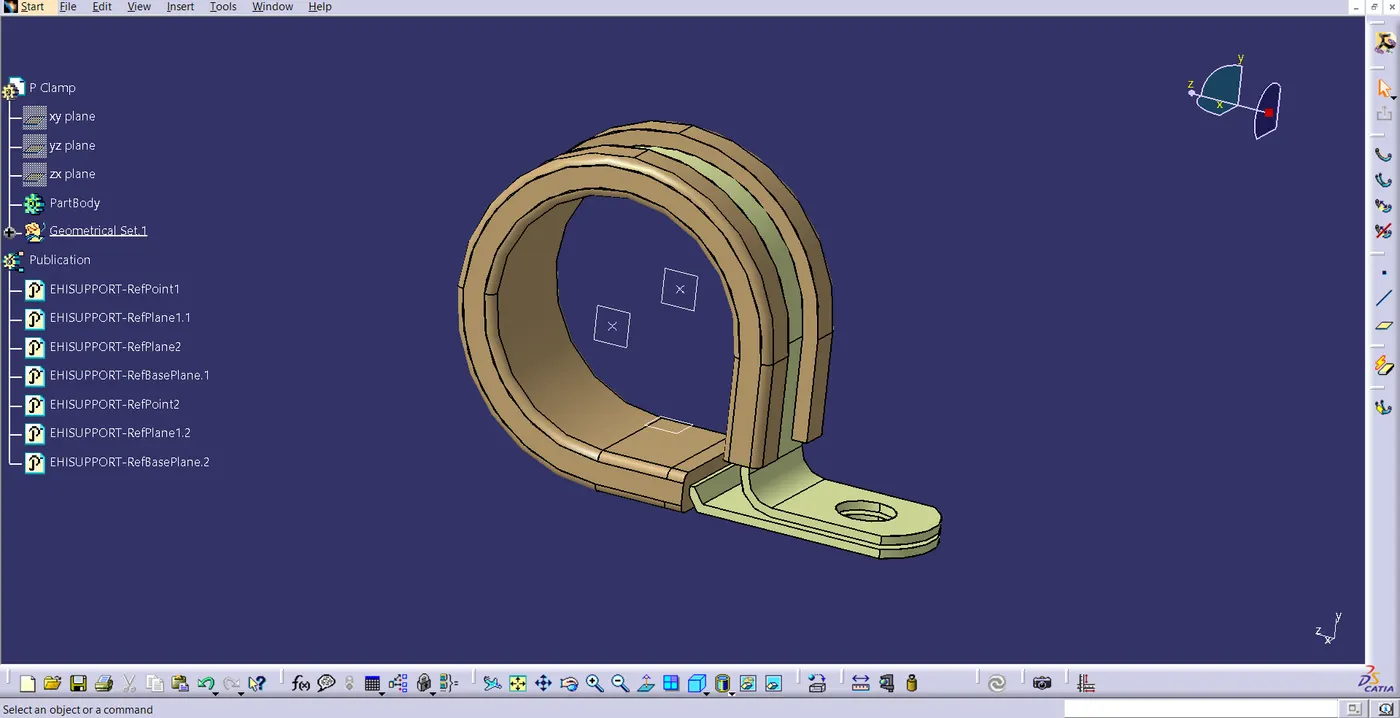
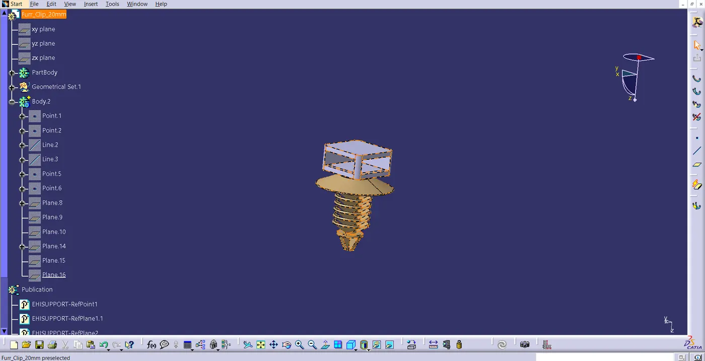
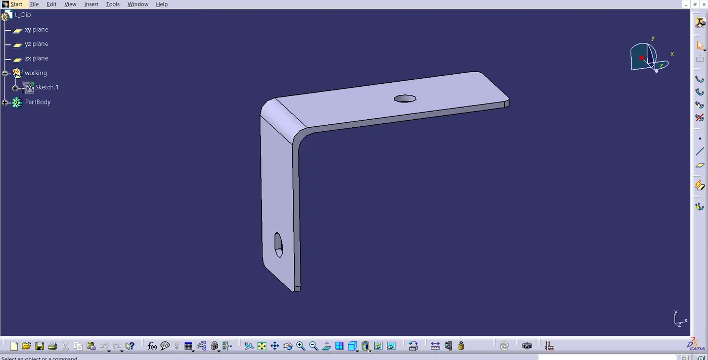
Step 5
- Generate a new product file for the cavity assembly and interconnection connector.
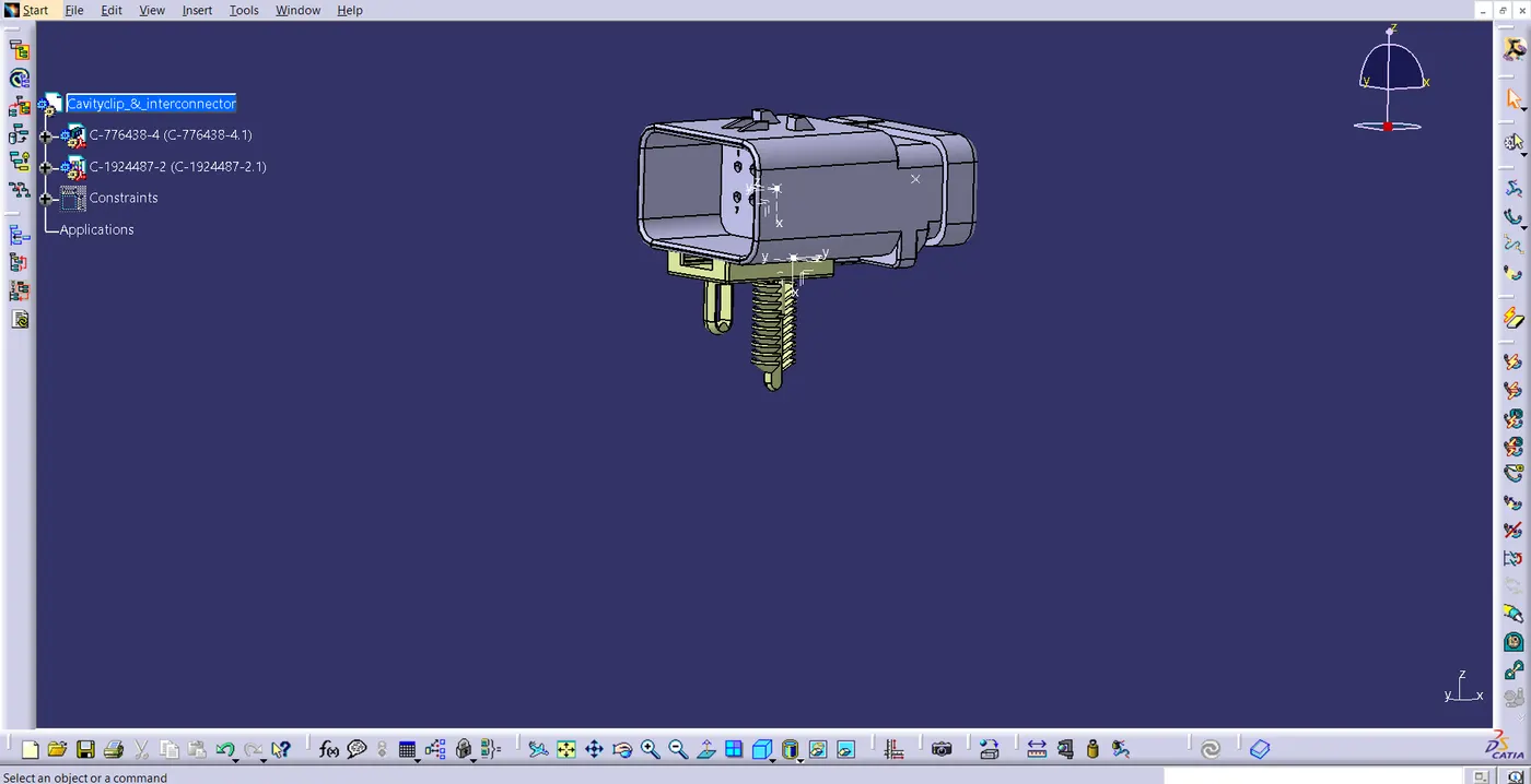
Step 6
- Context assembly is nothing more than the product file that includes the geometrical bundle of the engine harness and the engine's 3D-CAD data.
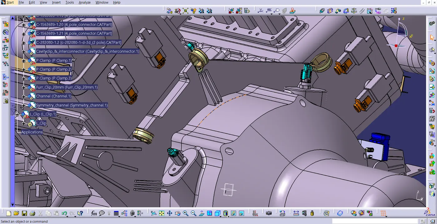
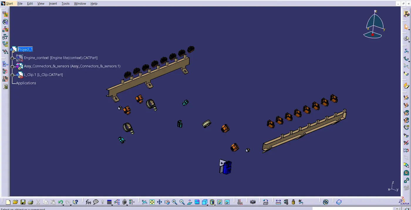
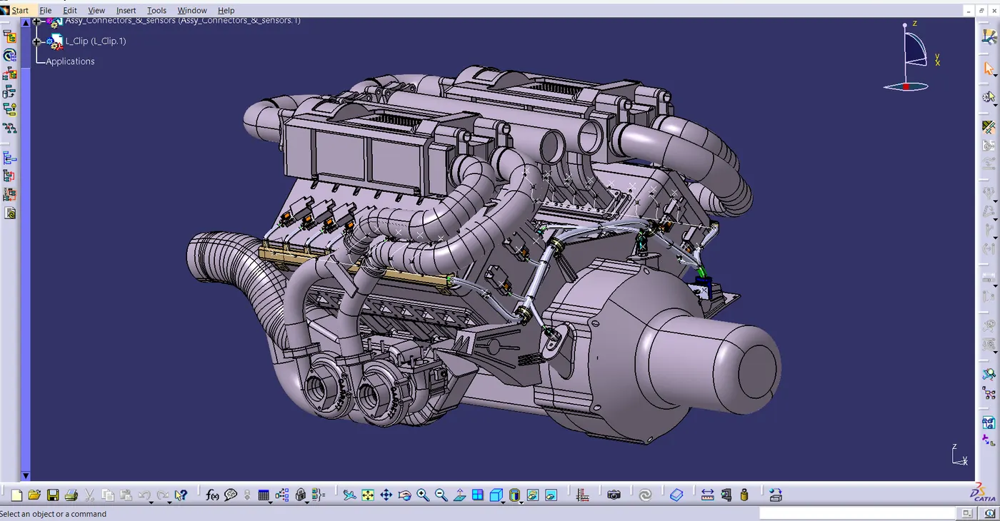
- In this case, the geometrical bundle product includes all of the electrically defined connectors, mounting hardware, clips, and clamps for the assembly. Addition of sheet metal L-clamps to the primary context assembly
- Before adding any parts, the Geometrical bundle product file needs to be electrically specified using the Define Geometrical bundle option.
- Next, we need to switch to the electrical harness assembly workbench.
- Assemble the required parts in the correct position. Connecting all the other sensor connectors, such as the neutral position sensor, speed sensors, and coolant heat sensor.
- In addition to assisting with proper routing, adding p-clamps and firtree clips can help shield the harness bundle from mechanical components that are not essential.
- If using clamps to achieve clearances in important places proves challenging, it is recommended to employ plastic guiding channels.
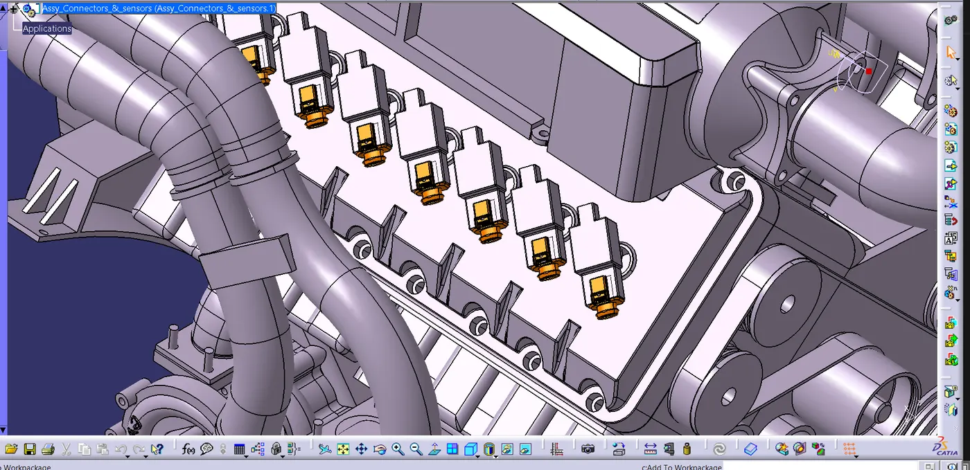
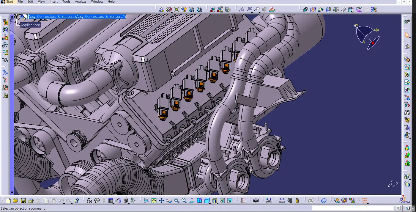
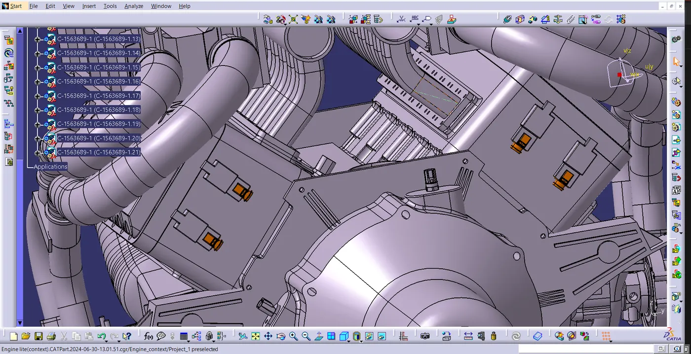
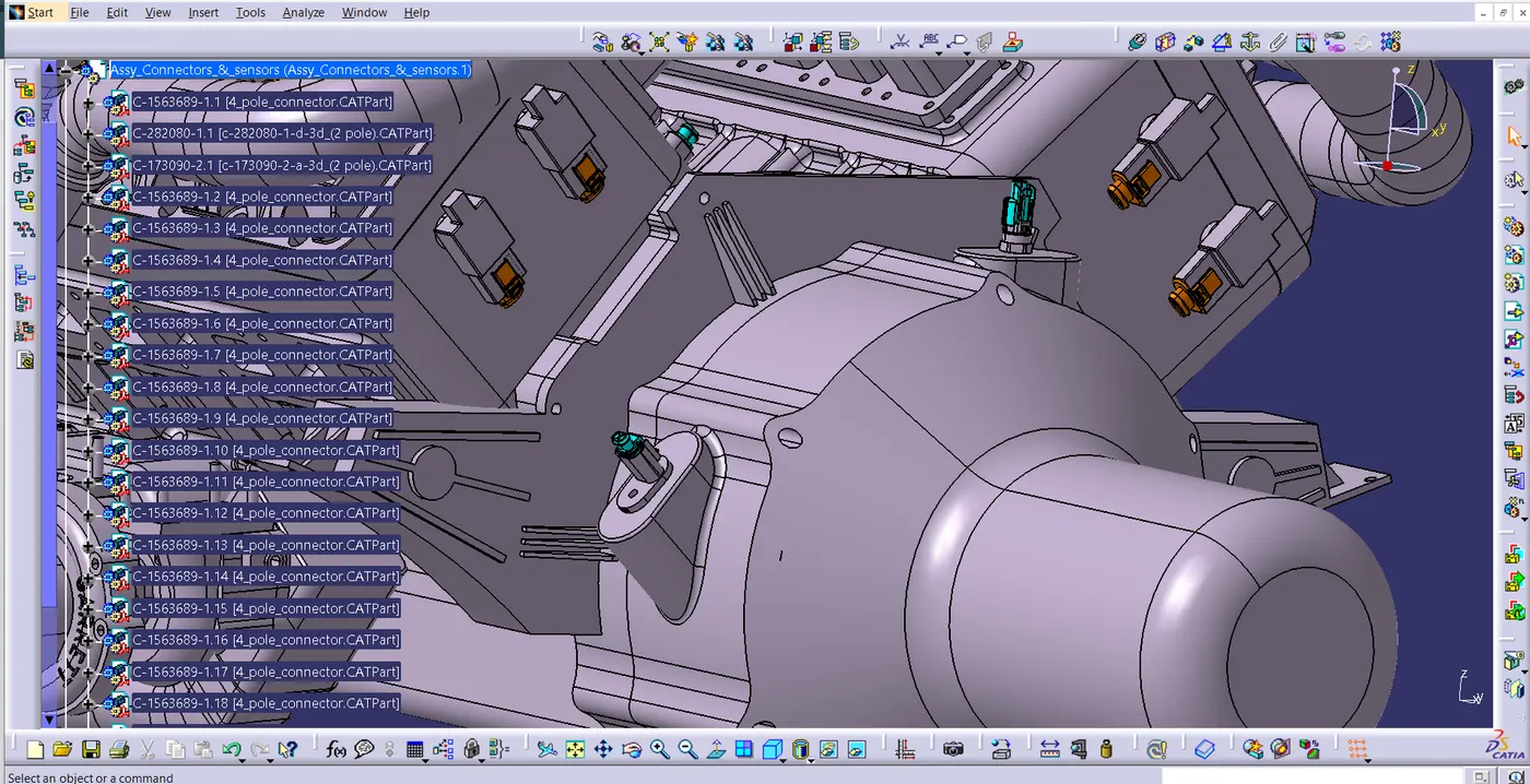
Step 7
- Route it by giving route definition.
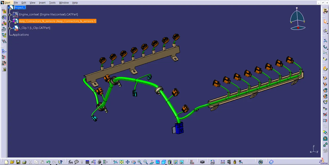
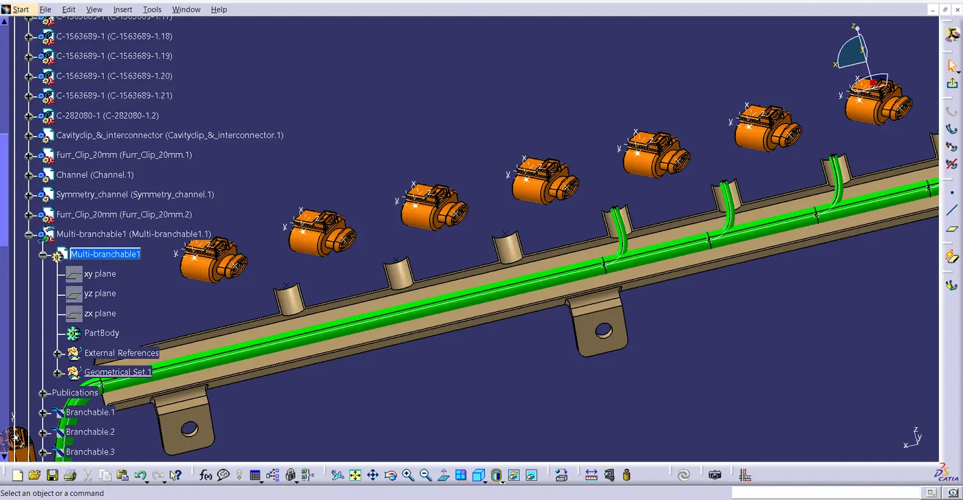
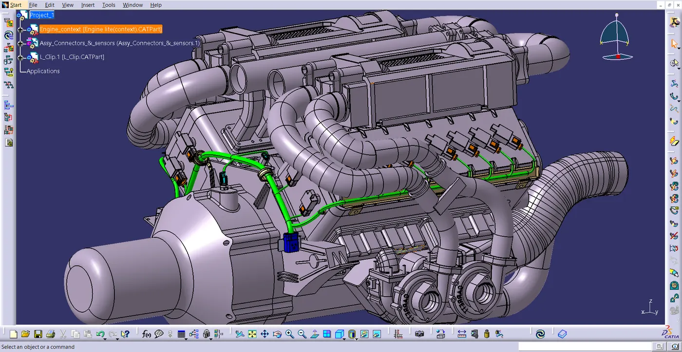
- Then provide protective covering in the required place.
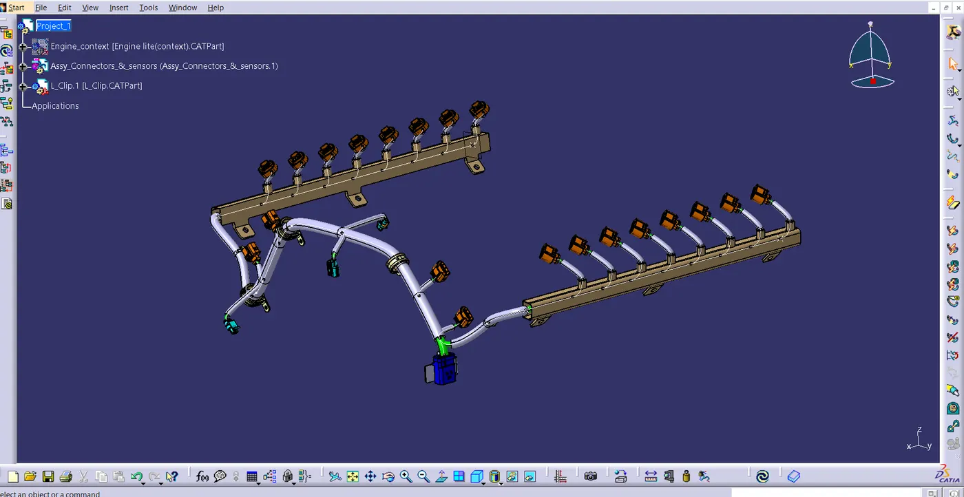
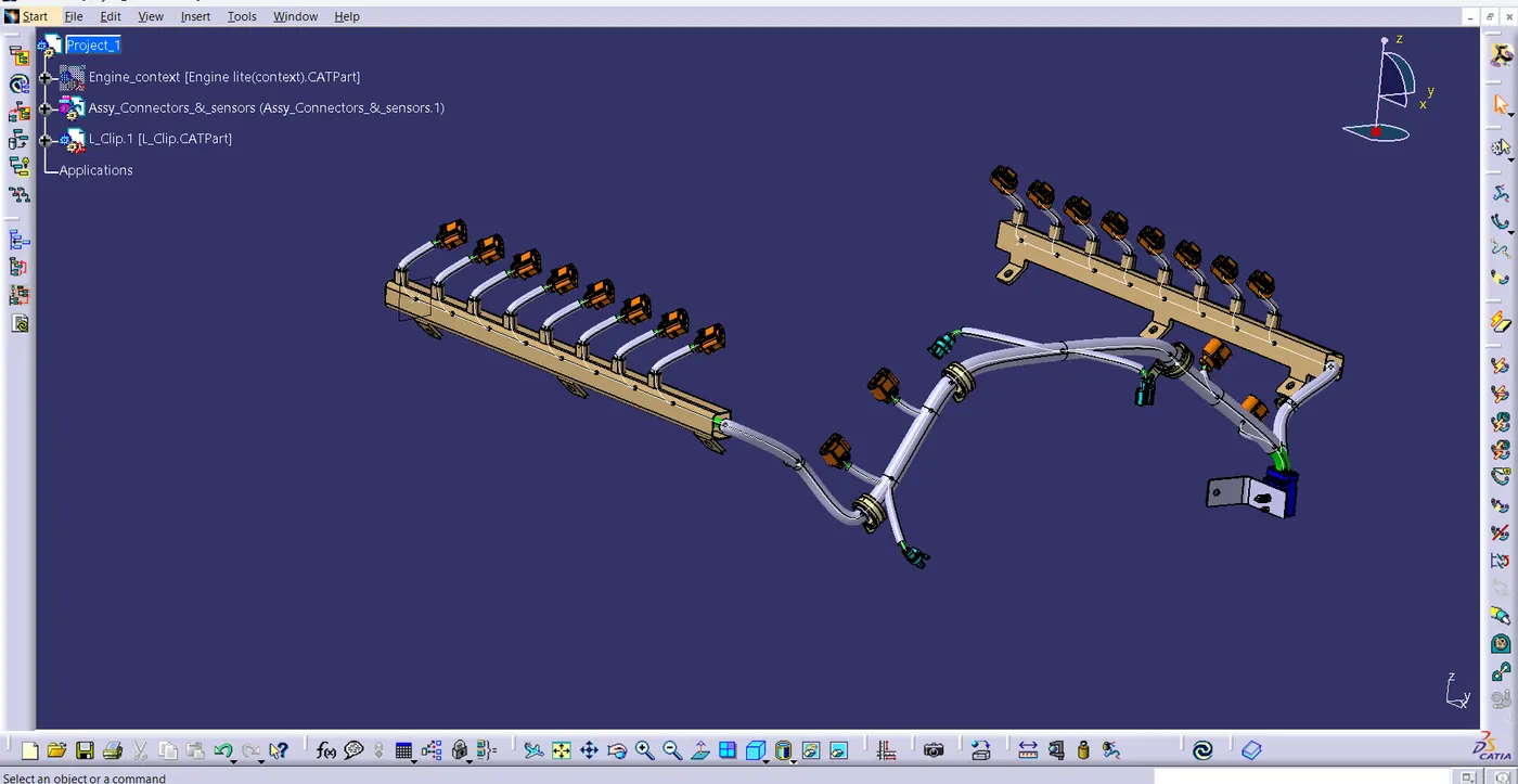
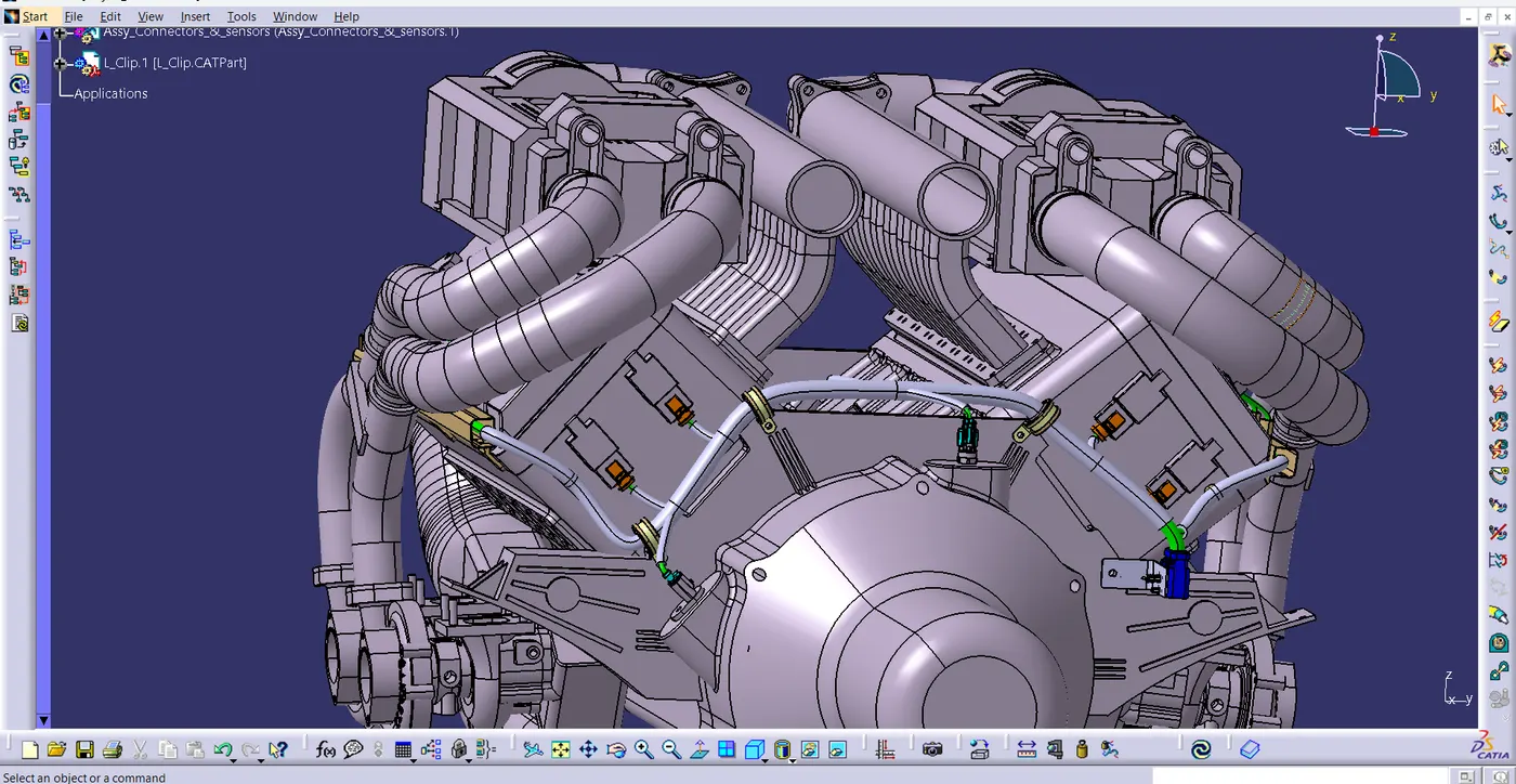
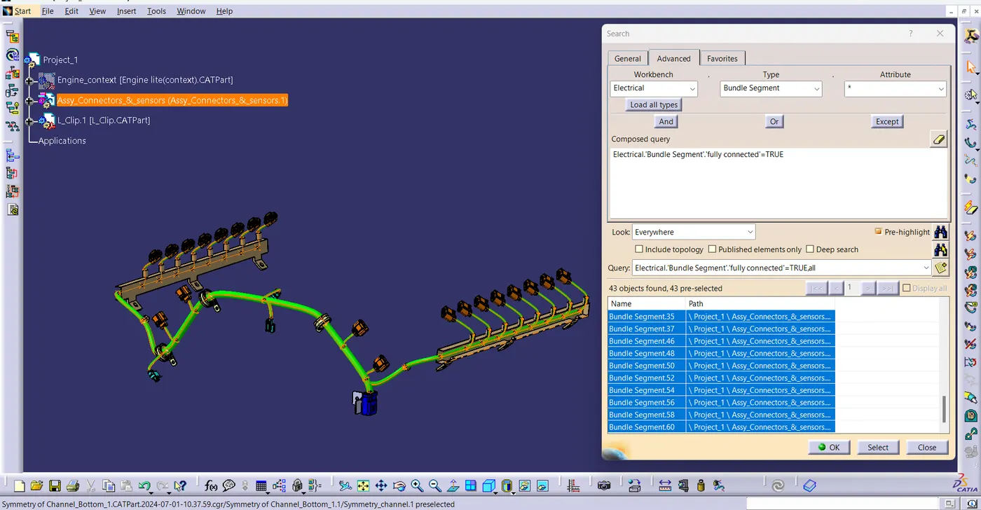
- Using search command in Edit toolbar, check the connectivity
- I have given the snaps of both the False and True attribute criterion respectively.
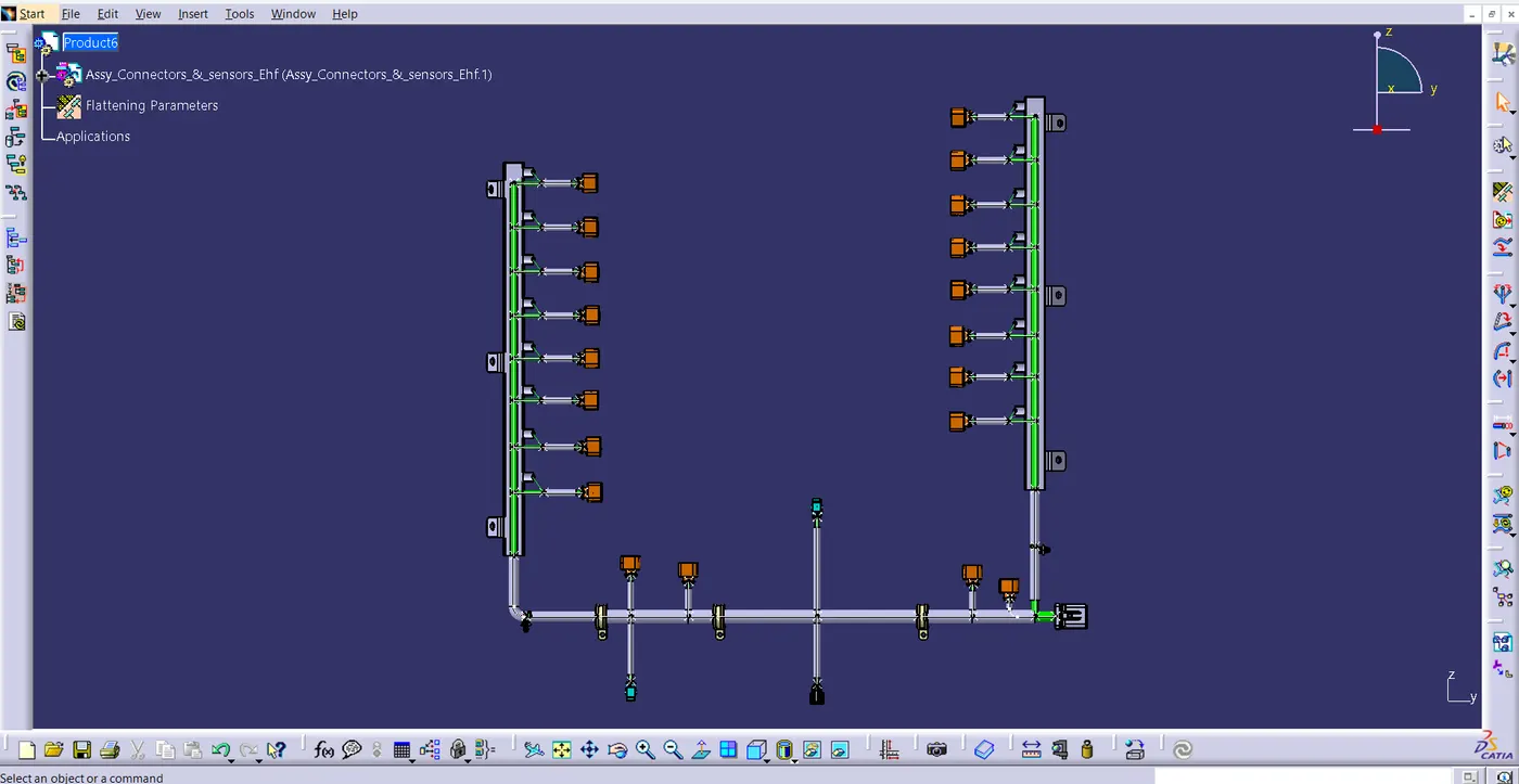
- Open a new product file in the Electrical Harness Flattening workbench after finishing the assembly.
- Define the necessary parameters, such as the plane, flattening orientation, and drawing, using the harness flattening parameter.
- Then, using the Flattening command, Flatten the branches by selecting the branches and the required plane.
- Using the commands like rotate and scale change the it to the required position. Flattening is completed.
PACKAGING RULES
- The cost-effectiveness of the bundle package should be taken into consideration when routing wires.
- To prevent sharp edges on sheet metal components; if this isn't feasible, then offer protective components to shield the wire bundle from harm.
- The wire harness should have enough slack to prevent damage during engine rocking or starting conditions.
- It is important to route the wire harness in a way that makes it simple to manufacture and maintain.
- To prevent the operator's blind zones from being routed and clipped during assembly and servicing.
- A wiring harness should not be routed close to the exhaust manifold or any of its parts, or near any other unshielded heat source, in order to keep the number of branches from a single branch point to four. If it is not possible to reroute, then keep a minimum of 200mm between objects.
- A minimum of 200mm should separate two straight connecting sites.
- There should be a minimum of 50mm separating two breakout spots.
- On a straight branch, there should be a minimum of 200mm between two clamps.
- A branch should have a minimum length of 50mm.
- There should be a minimum of 25mm between the clip and the closest branching point.
- Sufficient clamps must be supplied to guarantee the wiring harness's safety and positive clearance with the surroundings.
RESULT
We have Designed the wiring harness for the specified engine and created a flattened view design in CATIA V5. By putting into practice the industry best practices such as the application of all packaging regulations in design. Applied protective coverings when necessary.