Project 1
Given below is a plan view of a framing layout of a typical school classroom. Design beam marked B1 and the floor slab per IS 456-2000. Use M25 concrete and Fe 415 steel. Use 20 mm clear cover for slab and 30 mm clear cover for beam. Consider a 2.5 kN/m2 super imposed dead load accounting for floor finish and ceiling.
Answer:
Given That,
Strength of Concrete (Fck) = 25 Mpa
Strength of Steel (Fy) = 415 Mpa
Clear Cover of Slab = 20 mm
Clear Cover of Beam = 30 mm
Super Imposed Dead Load = 2.5 KN/m2
Solution,
Live Load (L.L) = 3 KN/m2 (IS 875: Part-2; 1987)
Assuming Total Depth of Slab (D) = 230 mm and Effective Depth (d) = 200 mm
Self-Weight of Slab = 25 * 0.23 * 1
= 5.75 KN/m
Total Dead Load (D.L) = 1.5 * (5.75 + 2.5)
= 12.375 KN/m
Total Live Load (L.L) = 1.5 * 3
= 4.5 KN/m
· Near Middle of End Span:
Md.l = + (1/12) * Wd.l * L2
= + (1/12) * 12.375 * 82
= 66 KN-m
Ml.l = + (1/10) * Wl.l * L2
= + (1/10) * 4.5 * 82
= 28.8 KN/m
M1 = 66 + 28.8
= 94.8 KN-m
· At Middle of Interior Span:
Md.l = + (1/16) * Wd.l * L2
= + (1/16) * 12.375 * 82
= 49.5 KN-m
Ml.l = + (1/12) * Wl.l * L2
= + (1/12) * 4.5 * 82
= 24 KN/m
M2 = 49.5 + 24
= 73.5 KN-m
· At the End Support:
Md.l = - (1/10) * Wd.l * L2
= - (1/10) * 12.375 * 82
= - 79.2 KN-m
Ml.l = - (1/9) * Wl.l * L2
= - (1/9) * 4.5 * 82
= - 32 KN/m
M3 = -79.2 - 32
= - 111.2 KN-m
ü LIMITING MOMENT (Mu,lim):
Mu,lim = 0.138 * Fck * b * d2
= 0.138 * 25 * 1000 * 2002
= 138 * 10^6 N-mm or 138 KN-m
# Mu,lim > Mu ; so, Section Depth is Sufficient
· Percentage of Steel (Pt):
Pt = 49.26 * (Fck / Fy) * [1 – Sq.rt {1 - (4.67 * Mu) / (Fck * b * d2)}]
= 49.26 * (25 / 415) * [1 – Sq.rt {1 – (4.67 * 111.2 * 106) / 25 * 1000 * 2002)}]
= 0.91 %
· Spacing (s):
MAIN BARS— Assuming 10 mm bar
Minimum Spacing (s) = 100 * Π * φ2 / Pt * d * 4
= 100 * Π * 102 / 0.91 * 200 * 4
= 43.15 mm
Maximum Spacing = Max { 300 or 3d
= Max { 300 or 3*200
= Max { 300 or 600 mm
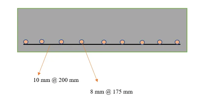
# Providing 10 mm bar @ 200 mm c/c
DISTRIBUTION BARS---- Assuming 8 mm bar
Minimum Spacing (s) < Π * φ2 * 100 / 4 * 0.12 * d
s < Π * 82 * 100 / 4 * 0.12 * 200
s < 209.44 mm
Maximum Spacing = Max { 450 or 5d
= Max { 450 or 5*200
= Max { 450 or 1000 mm
# Providing 8 mm bar @ 175 mm c/c
· DESIGNING OF BEAM
Area Load acting on Slab = Wu (assume)
UDL acting on beam = (3/2 + 3/2) * Wu
= 3 * Wu
Dead Load of Slab = 25 * b * D
= 25 * 1 * 0.23
= 5.75 KN/m
Super Imposed Load = 2.5 KN/m
Live Load = 3 KN/m
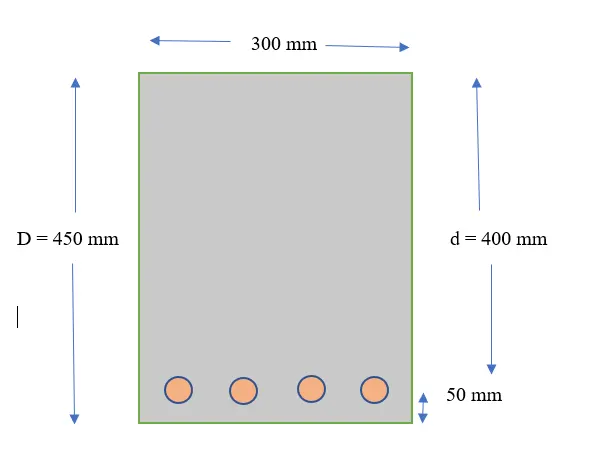
Assuming D = 450 mm, d = 400 mm, and b = 300 mm
Self-Weight of Beam = 25 * 0.3 * 0.45
= 3.375 KN/m
Total Dead Load (D.L) = 1.5 * (5.75 + 2.5 + 3.375)
= 17.45 KN/m
Total Live Load (L.L) = 1.5 * 3
= 4.5 KN/m
· Near Middle of End Span:
Md.l = + (1/12) * Wd.l * L2
= + (1/16) * 17.45 * 82
= 93.07 KN-m
Ml.l = + (1/10) * Wl.l * L2
= + (1/10) * 4.5 * 82
= 28.8 KN/m
M1 = 93.07 + 28.8
= 121.87 KN-m
· At Middle of Interior Span:
Md.l = + (1/16) * Wd.l * L2
= + (1/16) * 17.45 * 82
= 69.8 KN-m
Ml.l = + (1/12) * Wl.l * L2
= + (1/12) * 4.5 * 82
= 24 KN/m
M2 = 69.8 + 24
= 93.8 KN-m
· At the End Support:
Md.l = - (1/10) * Wd.l * L2
= - (1/10) * 17.45 * 82
= - 111.68 KN-m
Ml.l = - (1/9) * Wl.l * L2
= - (1/9) * 4.5 * 82
= - 32 KN/m
M3 = -111.68 - 32
= - 143.68 KN-m
ü LIMITING MOMENT:
Mu,lim = 0.138 * Fck * b * d2
= 0.138 * 25 * 300 * 4002
= 165.6 * 10^6 N-mm or 165.6 KN-m
Mu,lim > Mu ; so, Section Depth is Sufficient
o Percentage of Steel (Pt):
Pt = 49.26 * (Fck / Fy) * [1 – Sq.rt {1 - (4.67 * Mu) / (Fck * b * d2)}]
= 49.26 * (25 / 415) * [1 – Sq.rt {1 – (4.67 * 143.68 * 106) / 25 * 300 * 4002)}]
= 0.99 %
o Area of Steel (Ast):
Ast = (Pt/100) * b * d
= (0.99/100) * 300 * 400
= 1188 mm2
# Providing 20 mm dia bar
No. of Bar = Ast / (Π/4 * φ2)
= 1188 / (Π/4 * 202)
= 3.78 (round-off 4)
o Development Length (Ld):
Development Length (Ld) = (φ * σs) / (4 * τbd)
= (20 * 0.87 * 415) / (4 * 1.4)
= 1289.46 mm
Ld’ = (Ast,reqd / Ast,prov) * Ld
= (1188 / 4 * Π/4 * 20^2) * 1289.46
= 1219.03 mm (round-off 1220 mm)
o Anchorage Length (La):
Anchorage Length (La) = Max { d, 12φ, Clear Span / 16
= Max { 400, 240, 500
Taking 500 mm