Project 1
Project-1: Engine Wiring Harness Design
OBJECTIVE: To efficiently route the wiring harness for the car's engine body, adhering to industry packaging rules and best practices. This includes utilizing available connector 3D data sourced from www.te.com or other relevant sources and applying necessary protection coverings as per requirements. The project output comprises generating flattened wiring harness drawings and comprehensive reports of clearance analysis, clamping selections, harness fixing requirements and bundle continuity checks. The project aims to deliver a wiring harness system to the car's back door body that meets all functional requirements and quality standards.
GIVEN DATA:
V-16 Engine Surface Part:
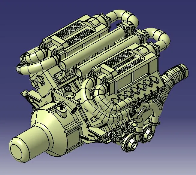
MAIN PROJECT:
Introduction:
The wiring harness design is a critical aspect of modern automotive engineering, particularly in the engine context. Serving as the nerve centre of the vehicle's electrical system, the engine wiring harness plays a pivotal role in ensuring the seamless integration and operation of various components essential for engine performance. From fuel delivery and ignition timing to emission control and sensor feedback, the wiring harness is the conduit that connects these intricate systems, facilitating efficient communication and power distribution throughout the engine bay. This project focuses meticulously on designing, implementing, and optimizing the wiring harness for the car's engine to deliver a harness that seamlessly integrates with the vehicle's overall electrical system, ensuring optimal performance and safety in every journey.
Effective Tips for Achieving Optimal Wiring Harness Routing:
1) Plan Ahead: Before beginning the routing process, carefully plan the path of wires that will follow. Consider factors such as component placement, accessibility, and potential sources of interference.
2) Follow Design Guidelines: Adhere to the design guidelines and specifications provided by the manufacturer or industry standards. These guidelines may include recommendations for wire spacing, bend radius, and clearance requirements.
3) Minimize Crossings: Minimize the number of wire crossings to reduce the risk of chafing, abrasion, and electromagnetic interference (EMI). Cross wires at right angles whenever possible to minimize contact and interference.
4) Avoid Sharp Edges and Obstacles: Route wires away from sharp edges, corners, and moving parts that could cause abrasion or damage. Use grommets, protective sleeves, or conduits to shield wires from potential hazards.
5) Secure Wires Properly: Use clips, clamps, zip ties, or adhesive mounts to secure wires along their path. Ensure that wires are adequately supported and do not hang or sag excessively, which could lead to strain and potential failure.
6) Maintain Separation: Keep high-voltage and low-voltage wires separate to prevent interference and minimize the risk of electrical faults. Use barriers or insulating materials to maintain separation between different types of wires.
7) Create Service Loops: Incorporate service loops or extra slack in the wiring harness at strategic points to allow for future adjustments, repairs, or component replacements without tension or strain on the wires.
8) Consider Environmental Factors: Consider environmental factors such as temperature variations, moisture, and chemical exposure when routing wires. Choose materials and routing methods that provide adequate protection against these conditions.
9) Label and Identify Wires: Label the wires regularly with identification markers or colour-coding to facilitate troubleshooting, maintenance, and repairs. Ensure that labels are visible and durable.
10) Test Routings: Before finalizing the routing of wires, conduct tests to verify that the proposed paths do not interfere with other components or systems. Make adjustments as necessary to optimize the routing for efficiency and reliability.
By following these tips, you can ensure proper wire routing, minimizing the risk of damage, interference, and electrical faults while maximizing the reliability and performance of the wiring harness.
Wiring Harness Routing Design for Engine:
STEP-1:- Establishing the Electrical Definition of Components
The CAD data for the connectors and the necessary mounting components for routing the wiring harness of the back door were downloaded. Subsequently, all geometry features and electrical properties were defined.
1) C-776438-4 (Inter-Connection Connector):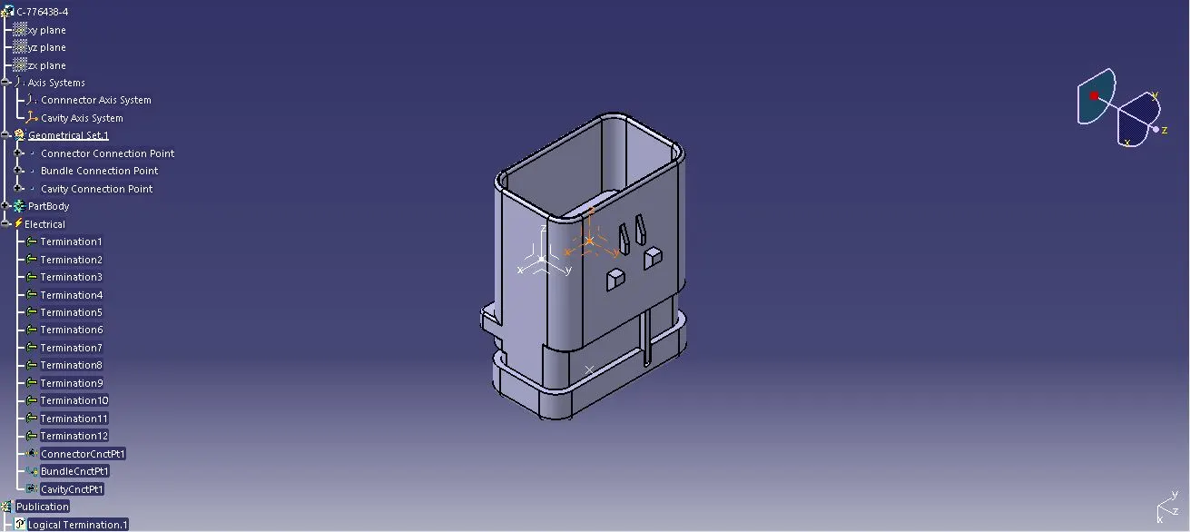
2) C-1924487-2 (ICC Cavity Clip):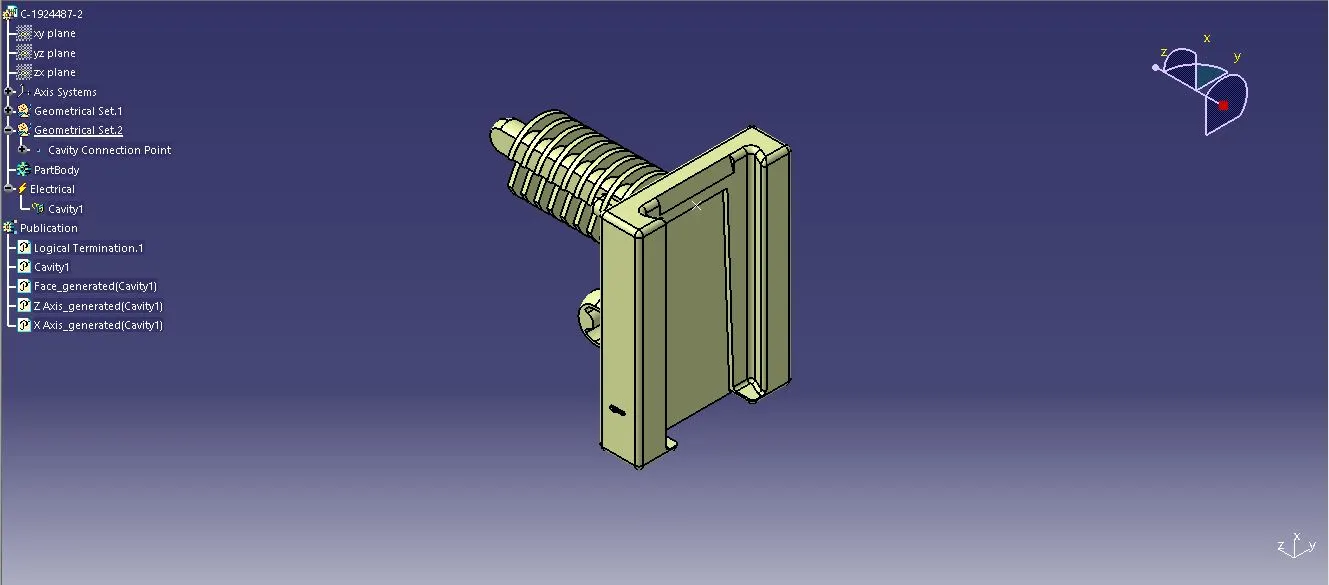
3) C-1563689-1: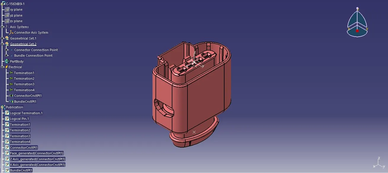
4) C-282080-1: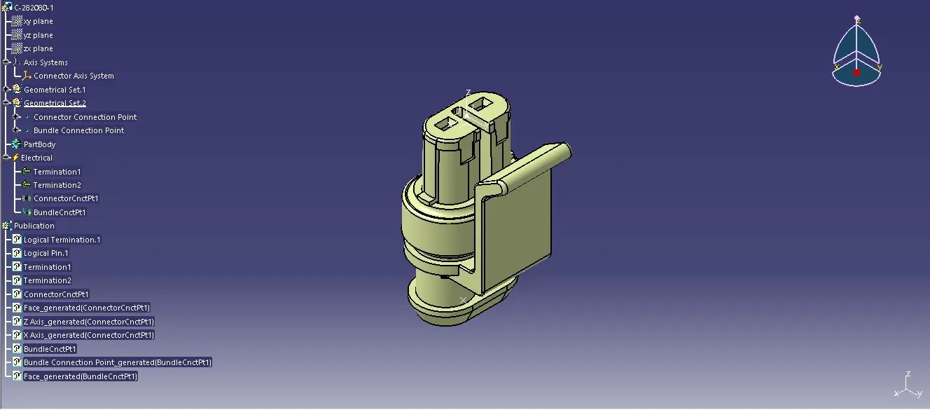
5) C-173090-2: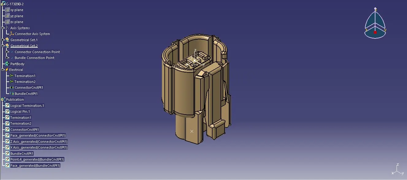
6) 2 Pole Connector: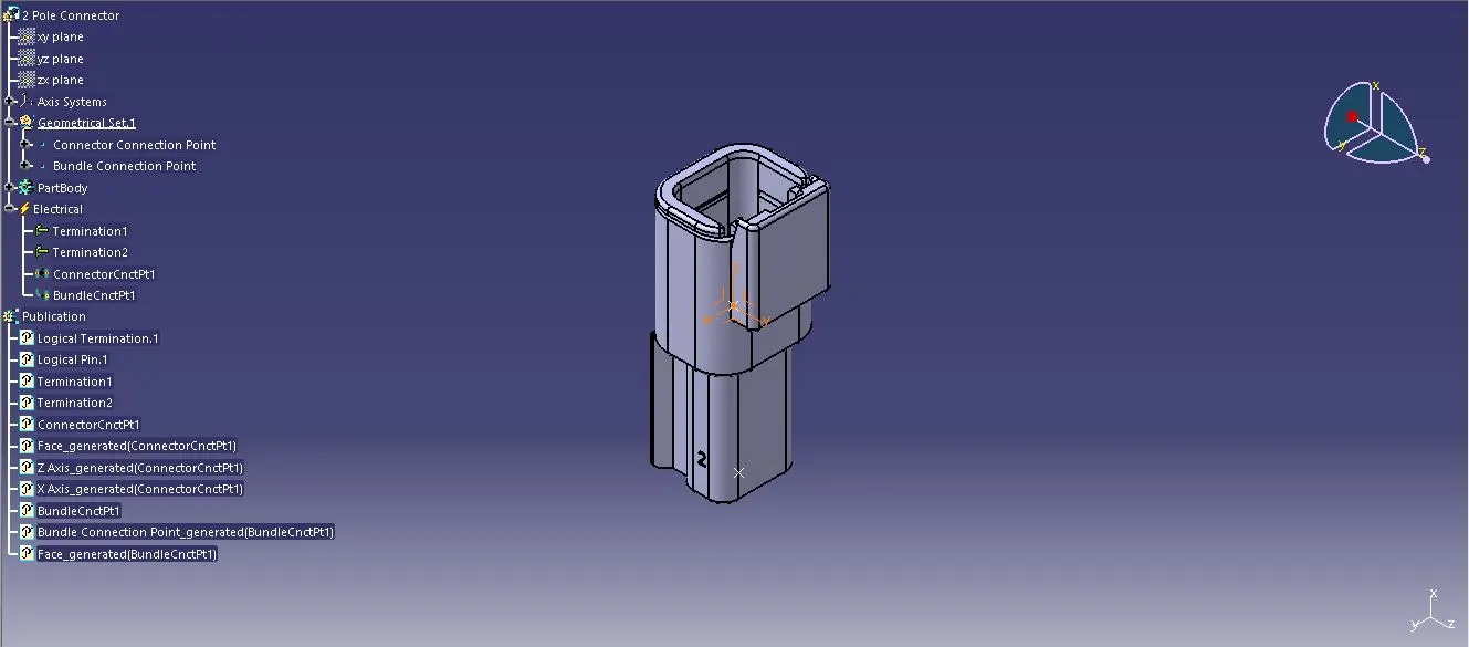
7) P-Clamp (Ø 28mm):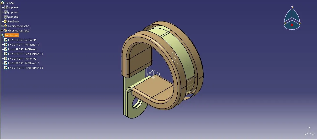
8) Fir Tree Clip (Ø 12mm):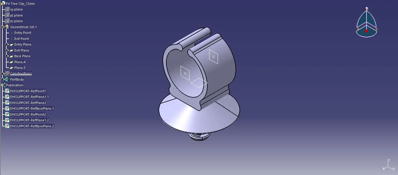
9) Plastic Guide Channel - Bottom (Right Side):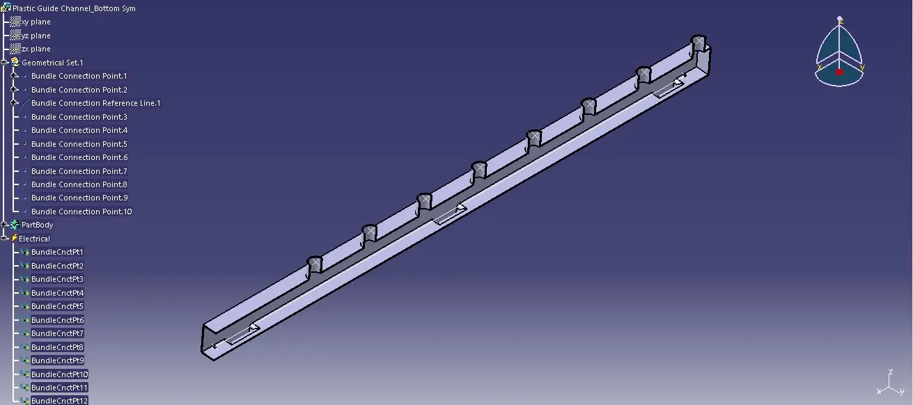
10) Plastic Guide Channel - Bottom (Left Side):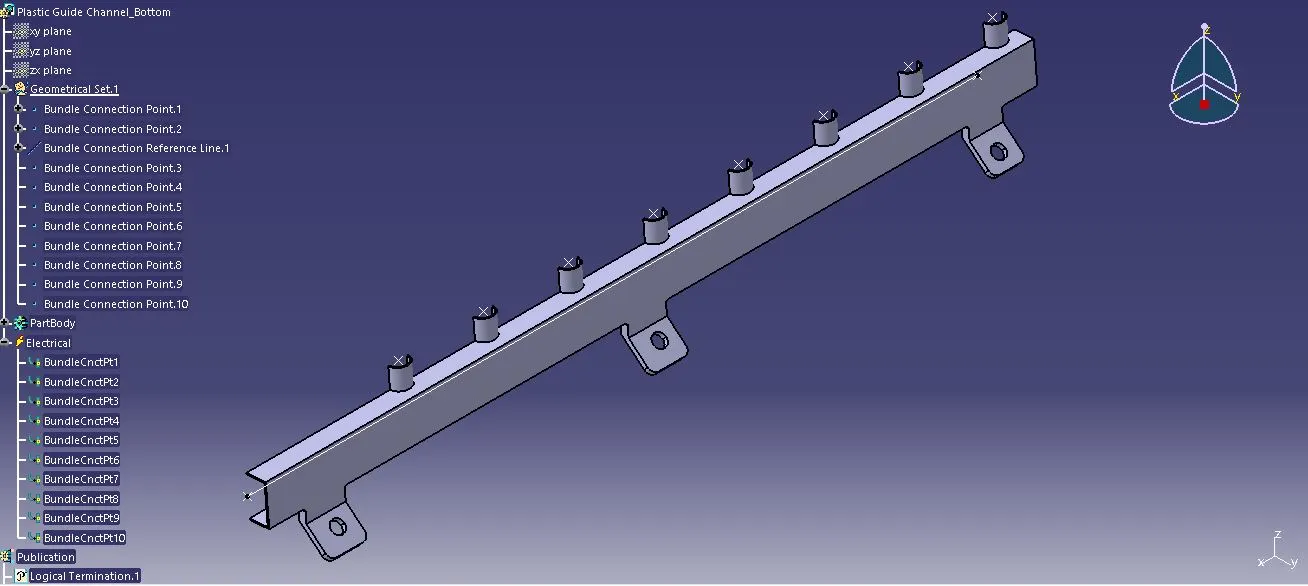
STEP-2:- Product Creation
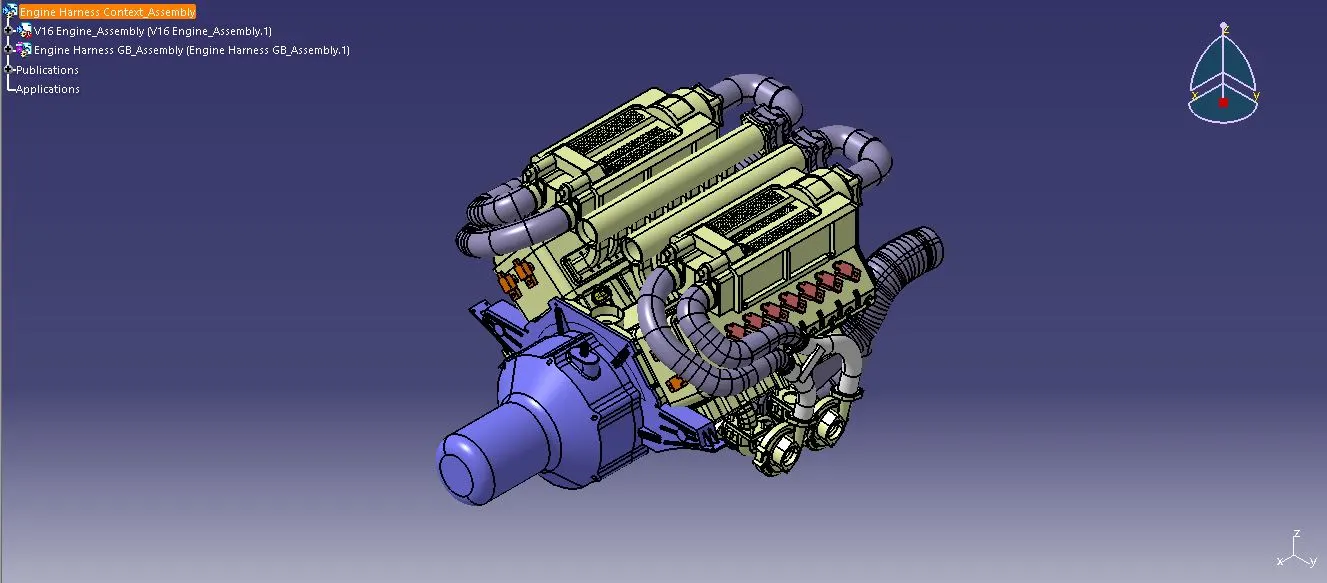
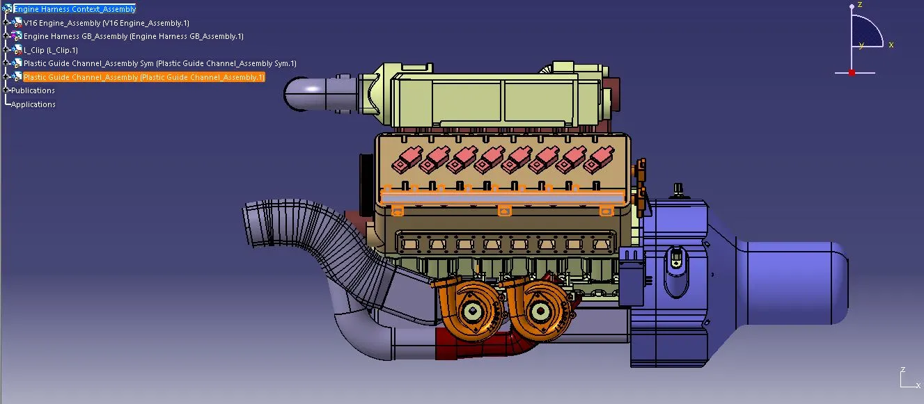
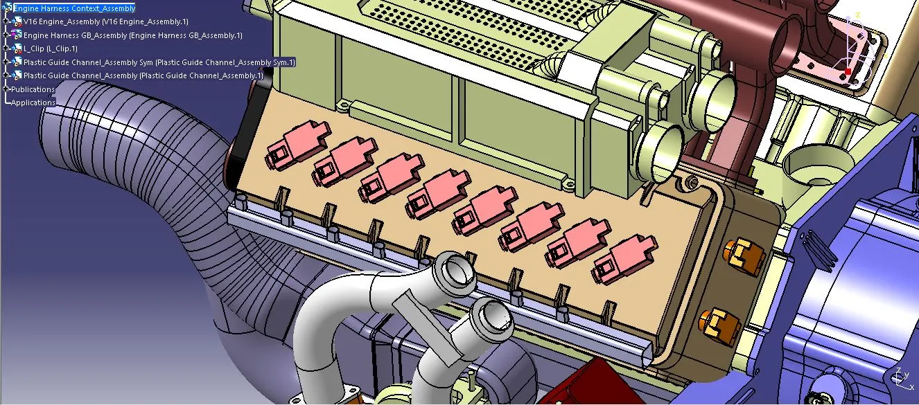
A new CAT product called "Engine Harness Context Assembly" was created and the given Engine Assembly was imported. Then, a new product named "Engine Harness GB Assembly" was created under the same product to position the connectors and route the geometrical bundle to them.
STEP-3:- Supports for Routing Wire Bundle
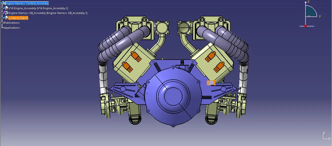
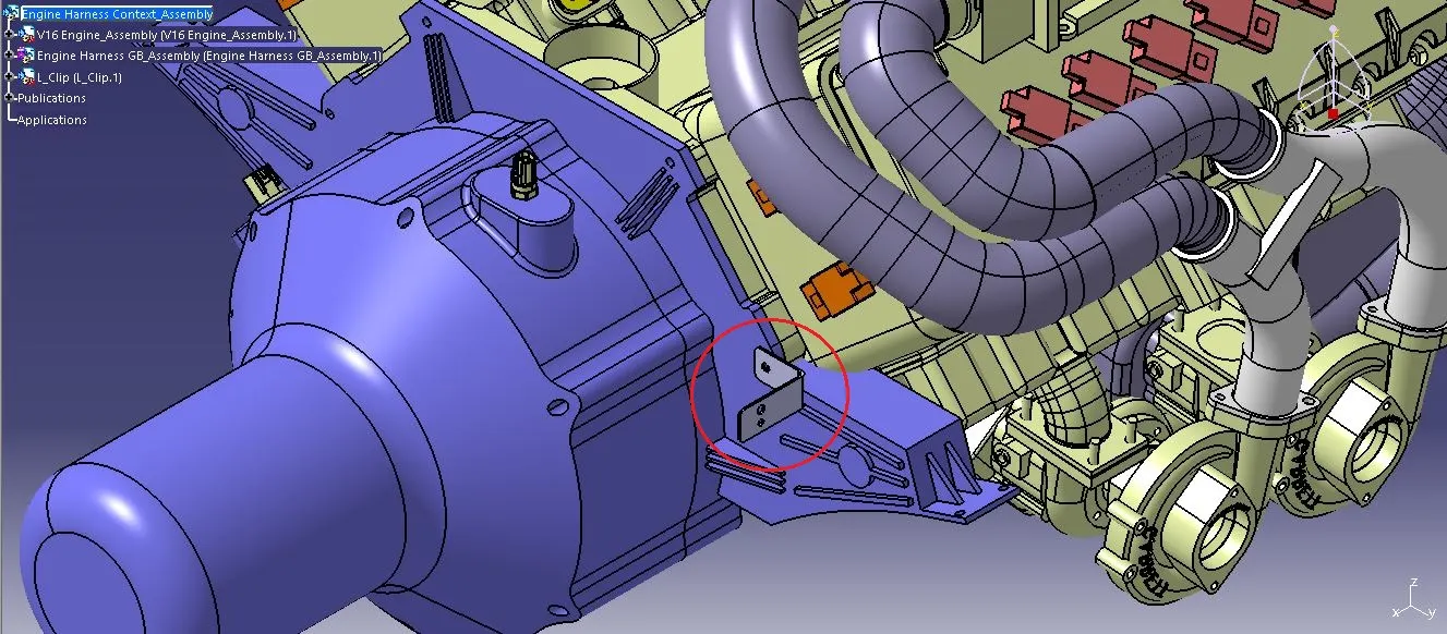
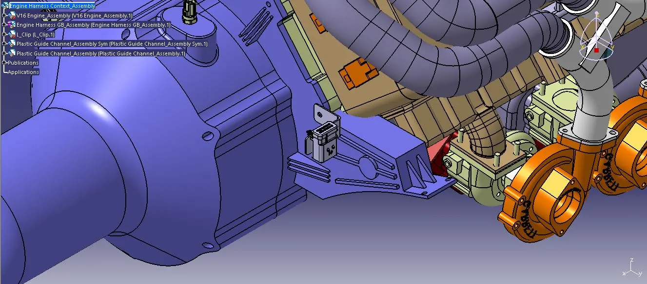
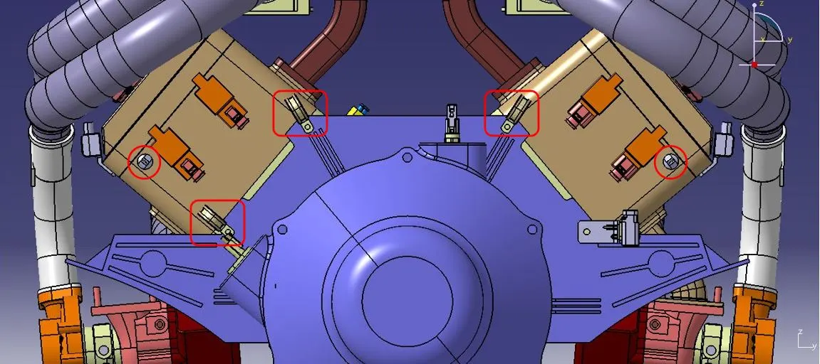
1) L-Clamp:- A dedicated L-clamp was mounted on the engine assembly to hold the inter-connection connector whereas, the rest of the connectors were provided with proper female connectors for placement.
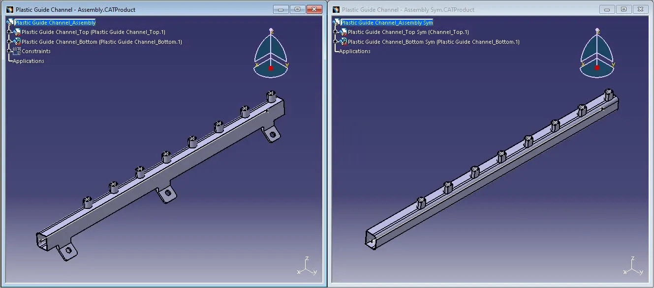
2) Plastic Guide Channel:- The purpose of the Plastic Guide Channel is to organize and secure the wiring harness within the machinery. It helps to route the wires along specific paths, preventing tangling or interference with other components, and maintaining a neat and orderly arrangement. The guide channel also protects the wiring harness from environmental factors such as heat, vibration, and moisture. Additionally, it aids in the installation process by providing a clear pathway for the wires to be routed efficiently during assembly.
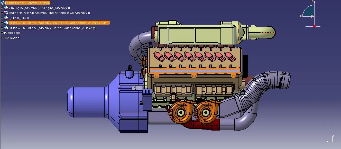
The plastic guide channel was composed of two parts: the Top and Bottom. These parts were assembled using assembly constraints. A mirrored assembly of the plastic guide channel was created for the opposite side of the engine. Subsequently, these two plastic guide channels were installed on both sides of the engine to facilitate the routing of the wire bundle.
STEP-4:- Importing Connectors into the Assembly
The electrically defined connectors were imported one by one under the "Engine Harness GB Assembly" product and positioned at respective locations on the engine by using various positioning commands like snap, smart move, manipulation, etc., available in the assembly workbench for easy wire harness routing.
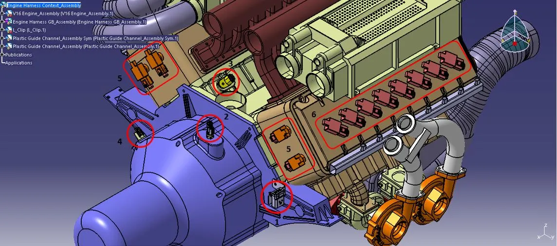
a) Inter-Connection Connector (C-776438-4):- Interconnection connectors are used in wiring harness design to facilitate connection between different segments or sections, making assembly, disassembly, and maintenance more efficient. It was securely mounted on the L-Clamp, ensuring stability and proper positioning.
b) 2 Pole Connector:- This connector was used to facilitate the electrical connections between the starter motor sensor and other components within the automotive systems for the exchange of data and signals for the vehicle's operation.
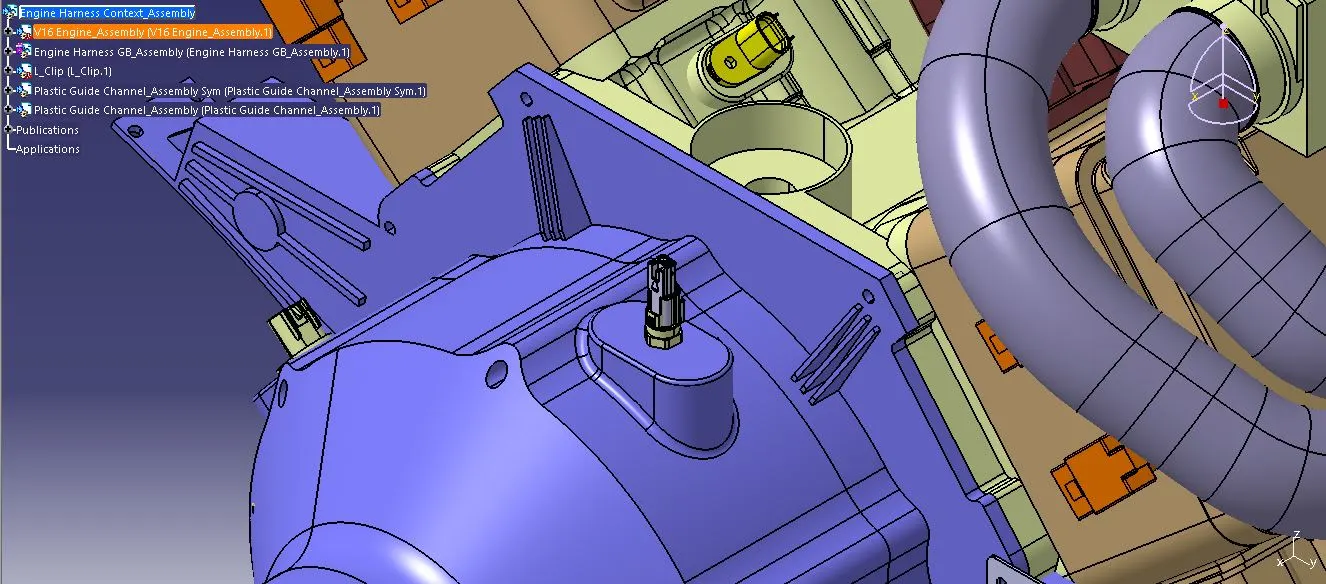
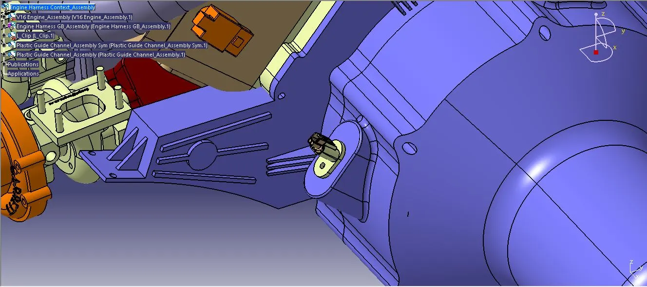
c) C-282080-1:- Similarly, this connector was used to facilitate the electrical connections between the knock sensor and other components within the automotive systems for the exchange of data and signals for the vehicle's operation.
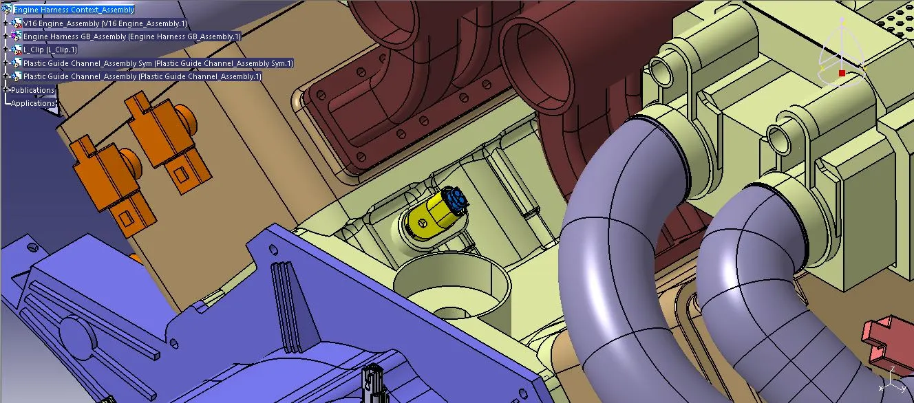
d) C-173090-2:- Likewise, this connector was used to enable electrical connections between the coolant temperature sensor and other components within the automotive systems for the exchange of data and signals for the vehicle's operation.
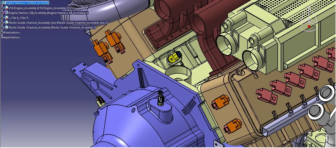
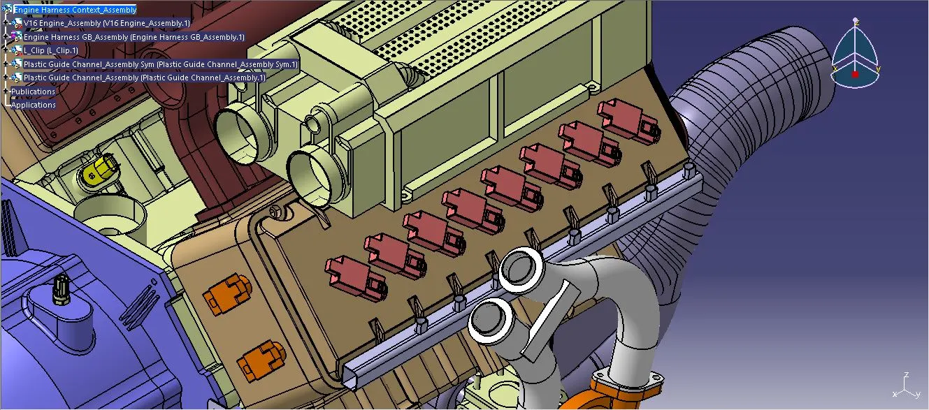
e) C-1563689-1:- This connector was employed for both the camshaft and ignition coil sensors, thus it was positioned at a total of 4 camshaft sensors and 16 ignition coil sensors combined.
STEP-5: Positioning of P-Clamp & Fir Tree Clips
1) The bundle diameter, branch points, and wire routing were planned once the connectors had been positioned at the ideal locations.
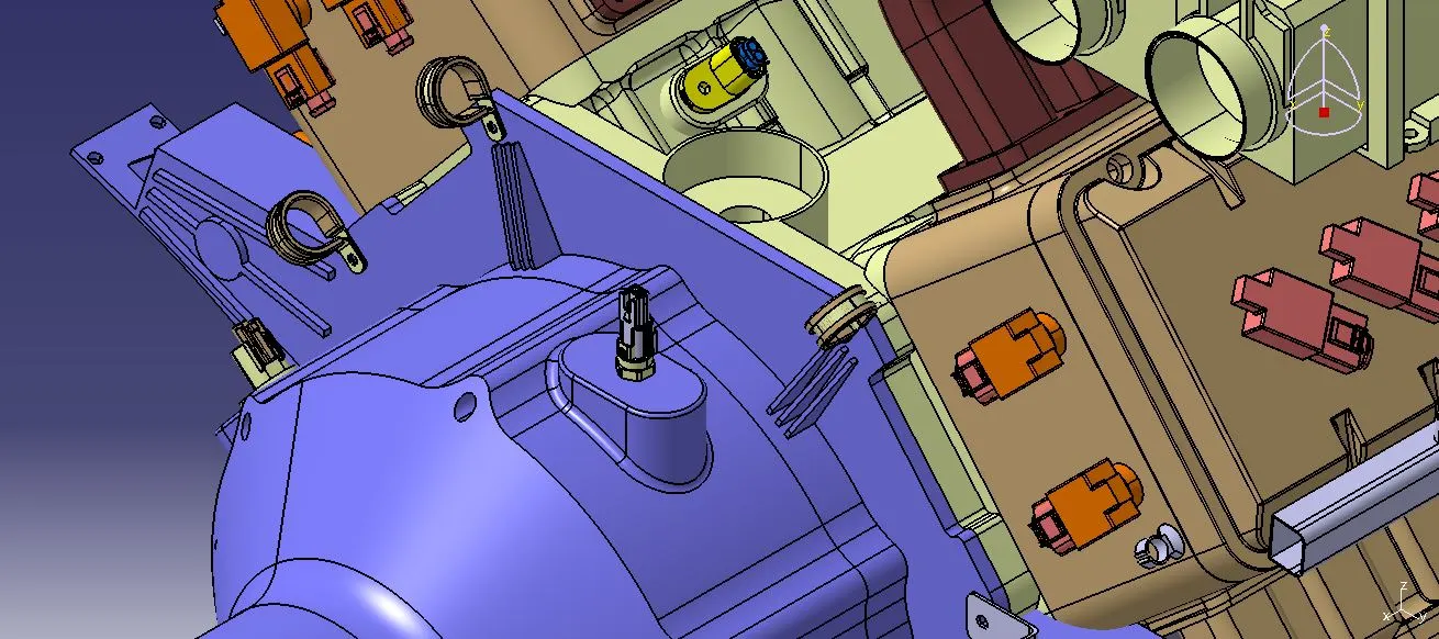
2) Following that, the P-Clamps were mounted on the engine hole slots and Fir Tree Clips were mounted randomly to route the harness branch to the plastic guide channel.
3) According to the design rules, a minimum gap of 50 mm was maintained between the fir tree clips to avoid too many fir tree clips and a maximum distance of 200 mm was not exceeded to prevent sagging between two fir tree clips.
4) If any additional fir tree clips were required for proper bundle routing and bundle safety, that was also communicated to the BIW Team.
5) After concealing and obtaining approval from the BIW Team, the fir tree clip positions were finalized and the fixation holes were created on the back door assembly by the BIW Team.
STEP-6:- Bundle Routing
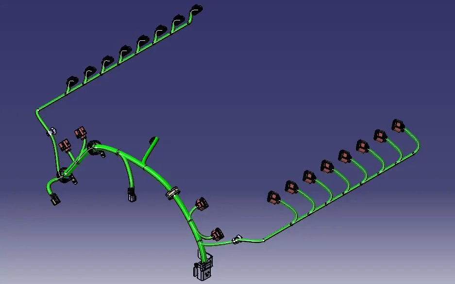
1) To route the wire bundle, we switched to the Electrical Harness Assembly Workbench and defined the "Engine Harness GB Assembly" electrically by using the command Geometrical Bundle available in the Electrical Harness Assembly Workbench.
2) Then for creating the branches, the Multi-Branchable Document command was selected and the bundle segments were created one by one.
3) Each branch segment was formed by individually selecting components according to the bundle routing plan. For instance, the Inter-Connection connector was initially chosen, followed by the selection of the fir tree clip to route the wire bundle.
4) The main branch started from the Inter-Connection connector and ended at the third P-Clamp.
5) The bundle diameter for the main branch was given 15mm and the minimum bend radius ratio was set to 1.5.
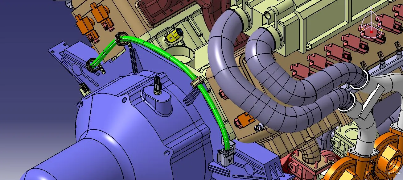
6) The branch points were created at appropriate distances to create and route the harness branch to the connectors individually from the main branch.
7) A 10 mm bundle diameter harness branch was used to route the wire bundle for connectors. Then the minimum bend radius ratio was set to 1.4.
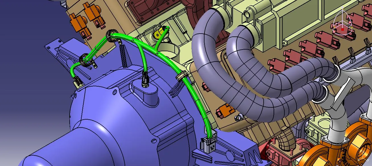
8) An 8 mm bundle diameter harness branch was employed to route the wire bundle for both camshaft and ignition sensor connectors. Plastic guide channels were utilized to route the wire bundle to the fuel injectors. Subsequently, a minimum bend radius ratio of 1.4 was established for both harness branches.
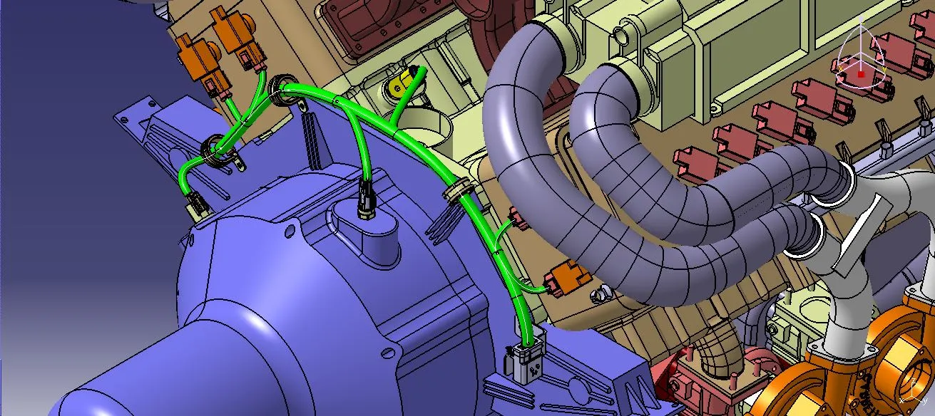
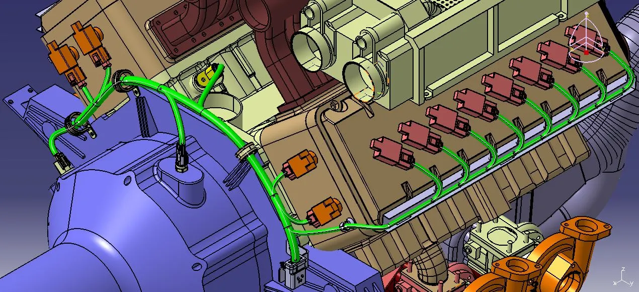
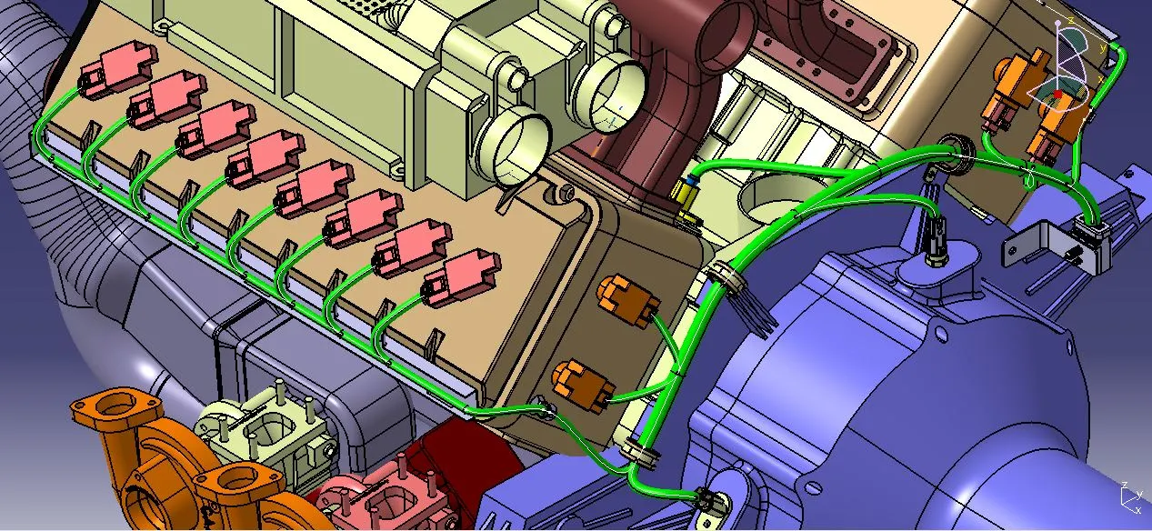
9) A certain percentage of slack was provided for some bundle segments for proper routing and easy serviceability.
STEP-7: Bundle Continuity Check
Bundle continuity in a wiring harness assembly is to check a seamless and unbroken electrical connection throughout the entire layout of the bundled wires. It helps to ensure that there are no interruptions or discontinuities in the electrical lines within the harness. Checking bundle continuity involves verifying that all wires within the harness are properly connected, with no breaks or disruptions, contributing to the overall functionality and reliability of the electrical system.
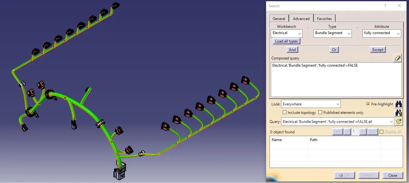
The bundle connectivity was examined for the designed wiring harness and there were no breaks or discontinuities on it.
STEP-8:- Applying Protective Covering
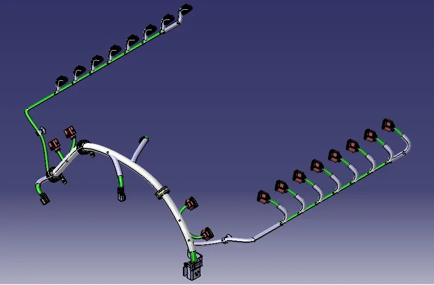
Corrugated tubes were provided for all the bundle segments based on the bundle diameter as a protective covering with an end extremity at 30mm from the connector's end.
STEP-9:- Wiring Harness Flattening
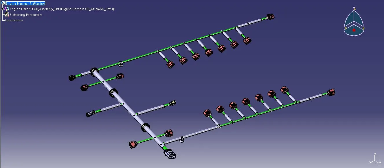
1) A new product file was created and switched to the Electrical Harness Flattening Workbench. Then, I saved the file as Back Door Harness Flattening in the same location where all the files were stored.
2) The 'Harness Flattening Parameters' settings were defined to flatten the wiring harness assembly.
3) The 'Extract' option was selected in the Electrical Harness Flattening Workbench, and the "Engine Harness GB Assembly" Product was selected in the "Engine Harness Context Assembly" product file. Subsequently, the Geometric Bundle assembly was imported into the Wire Harness Flattening product file with an 'EHF' extension.
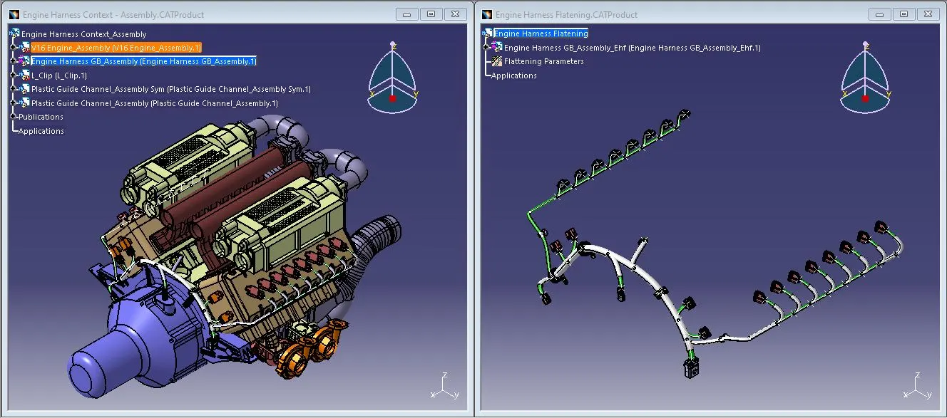
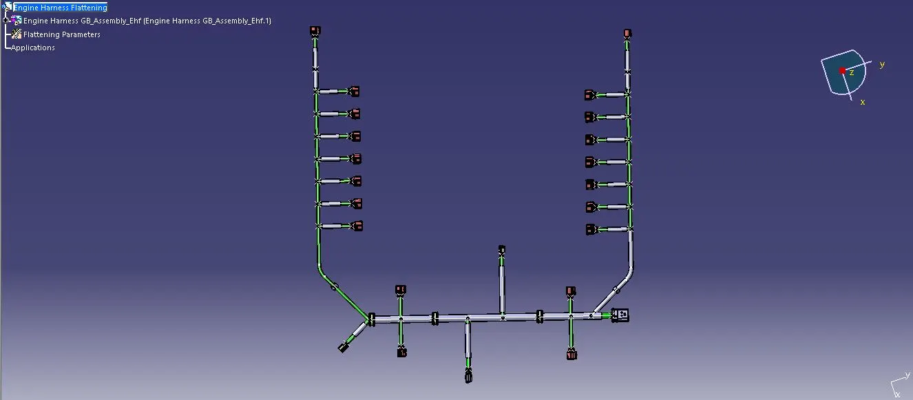
4) Select the Flatten option, provide the active plane and define the algorithm and angle mode. Then choose the branches which are to be flattened and hit the ok button.
5) Rotate and Quick Roll commands were used to align the branches properly and orient them ton form a layout.
STEP-10: Drawing View
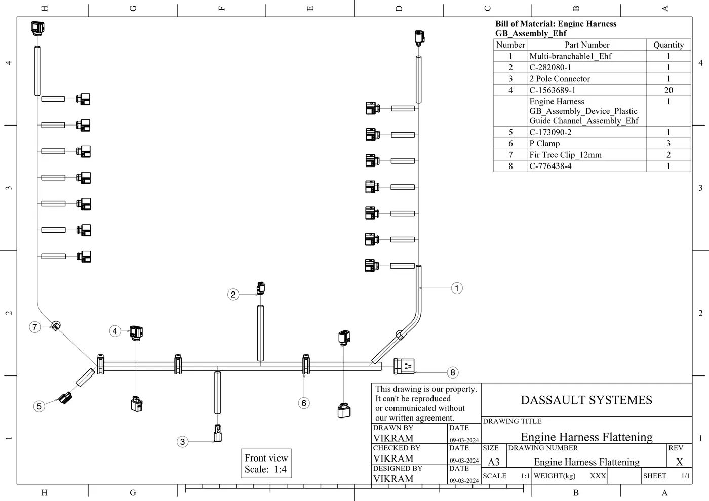
1) A new drawing file was created and ensured to be saved in the same designated location. The title block template was inserted into the drawing sheet, and the necessary details were entered within the title block.
2) The front view of the harness assembly was inserted by selecting any flat face of the connector. The orientation of the wire harness was adjusted for better viewing.
3) The properties were accessed, and the '3D Wireframe' and 'Is always visible' options were enabled to ensure a clear visualization of wire bundles, connectors, and protective coverings.
Conclusion:
Thus, the required connectors and mounting clips are electrically defined and routed the wire harness design successfully for the engine body by following the industry packaging rules and best practices. On top of that, the corrugated tubes were provided as a protective covering for the geometrical bundle and validated the bundle continuity checks, clamping selections and harness fixing requirements.