Project 1
OBJECTIVE-Route the Wiring harness on Given Engine and Prepare flattened view drawing in CATIA V5. Apply Protection coverings as required.Prepare & Submit all necessary reports like clearance, Clipping/Clamping selection, Harness fixing requirements, Harness continuity, and Assumptions if any along with CATIA 3D data.
INTRODUCTION
An Engine Wiring Harness is constricted Wires , Cables, terminals , and Connectors Controlling a vehicle's electrical system. It relays electrical Power and Control Information to Components Such as batteries, alternators , fuel injectors, fuses , audio systems, blower motors , fuel Injectors, and Computers. Wire harness companies customize it for every location, application, and design it interconnects. Also Known as Cable harness, it is more than just a collection of multiple of wires Put together.
It manages the key functions around the engine Including Engine controller, oil controller gate, transmission plug housing, air Pipe Sensors, Pressure Sensors, and Water temprature Sensors.
DESIGN METHODOLOGY
download the engine CAD data and required connectors CAD data from the given source.
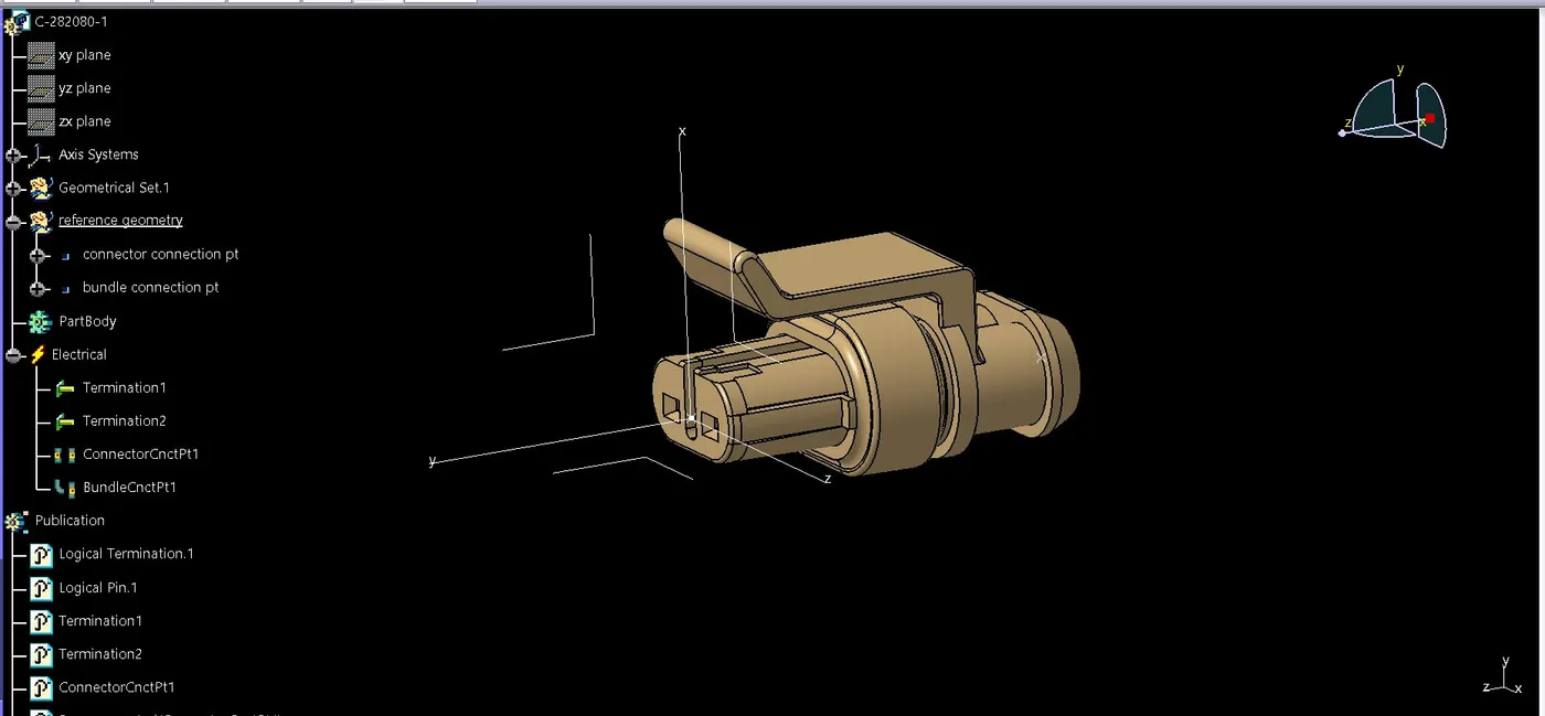
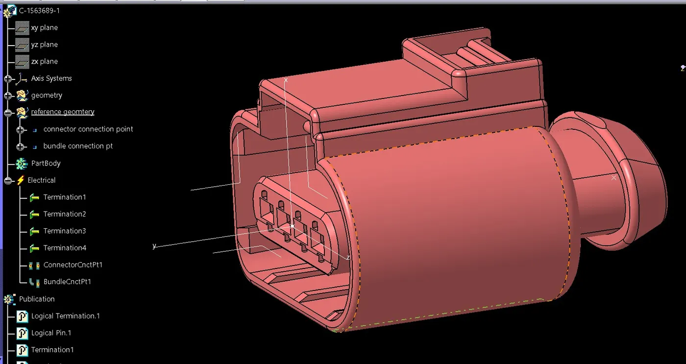
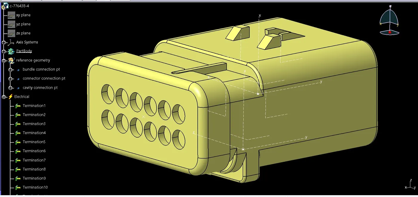
Convert the connectors as Electrical part by following steps
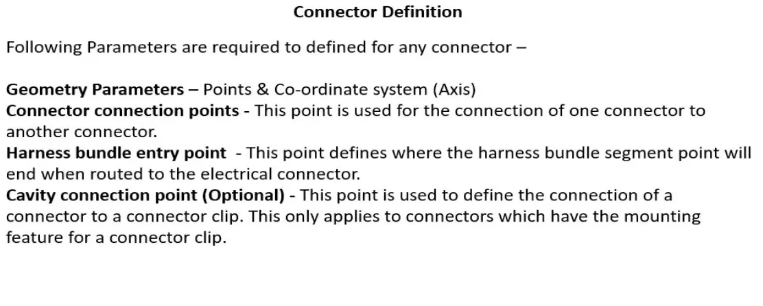
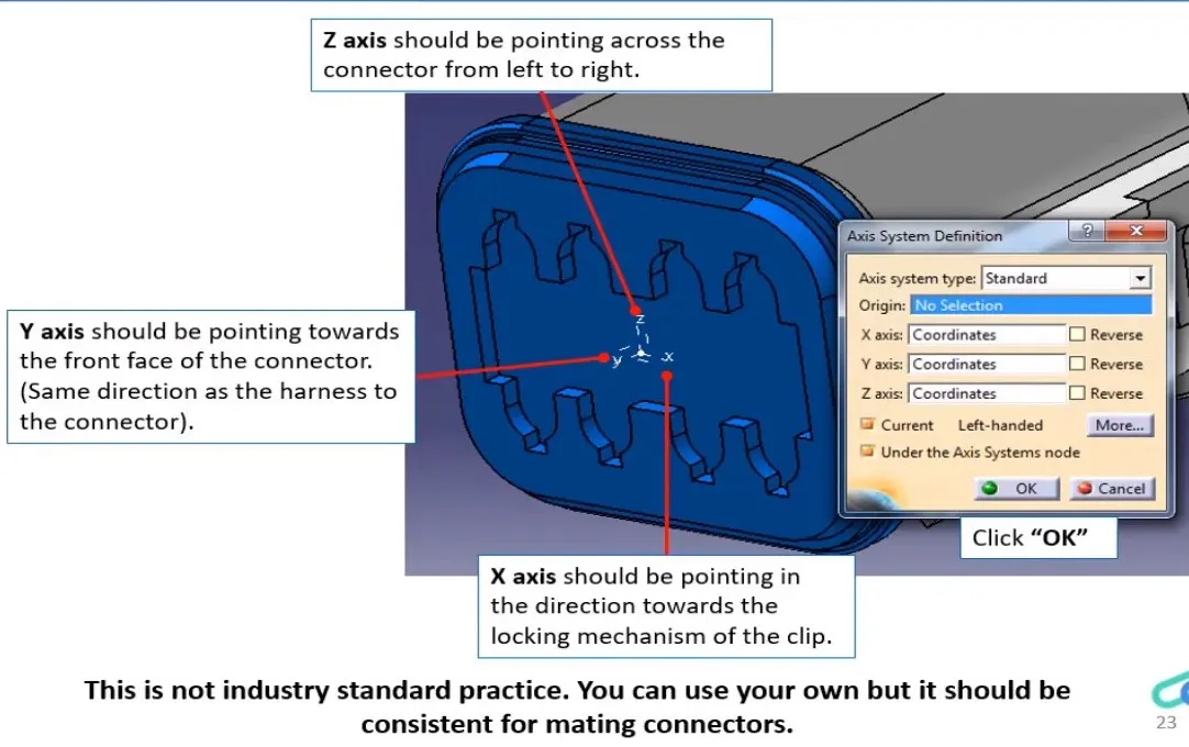
C-173090-2
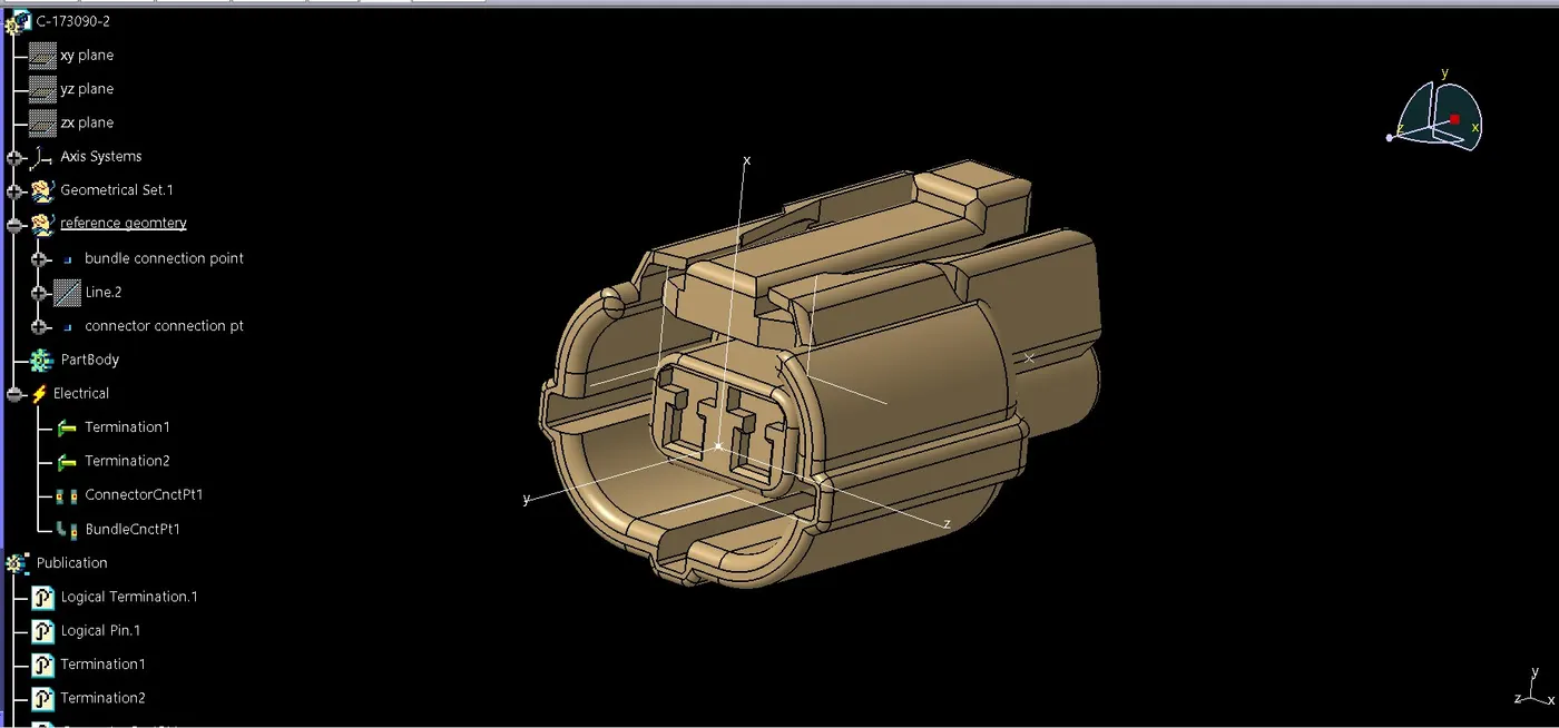
C-282080-1
C-1563689-1
C-776438-4
CONVERT MOUNTING CLIPS AS ELECTRICAL PART BY FOLLOWING PROCESS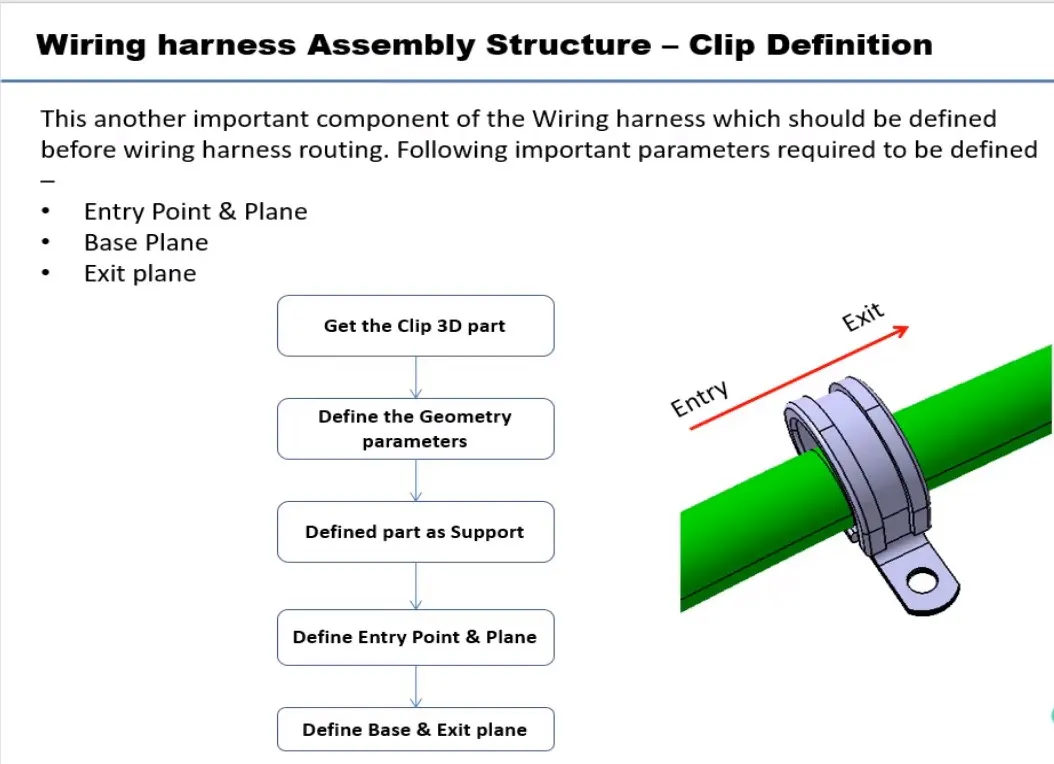
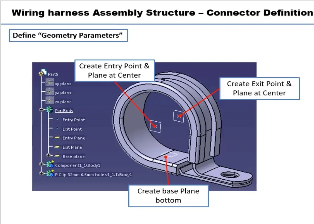
P-CLAMP
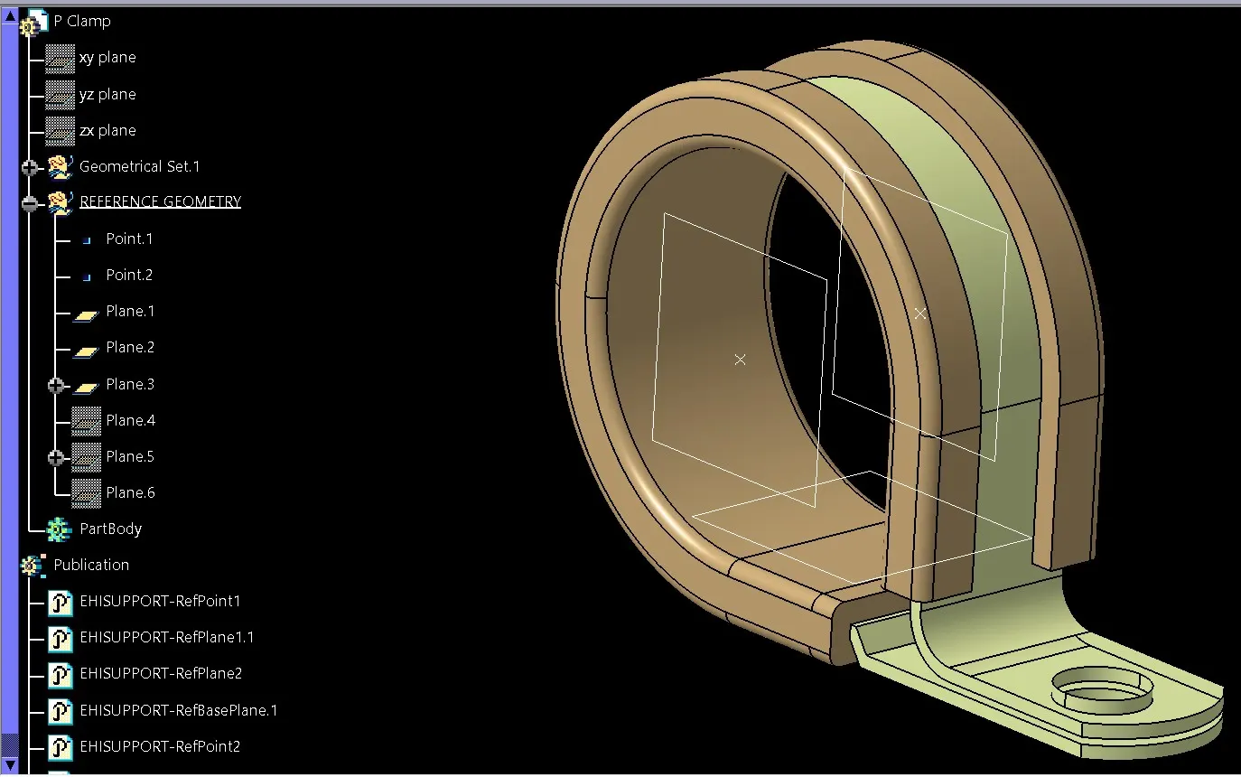
FIR TREE CLIP
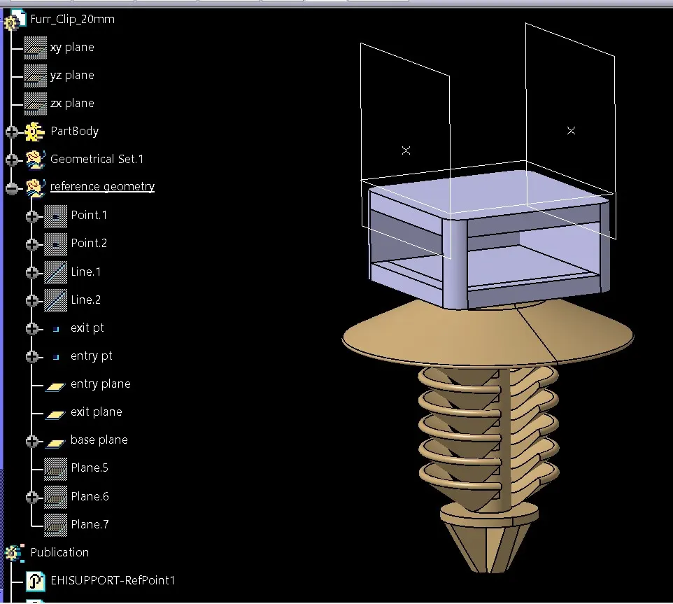
MOUNTING CLIP 1924487-2
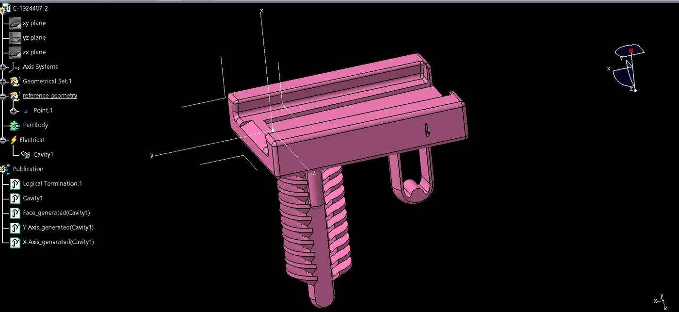
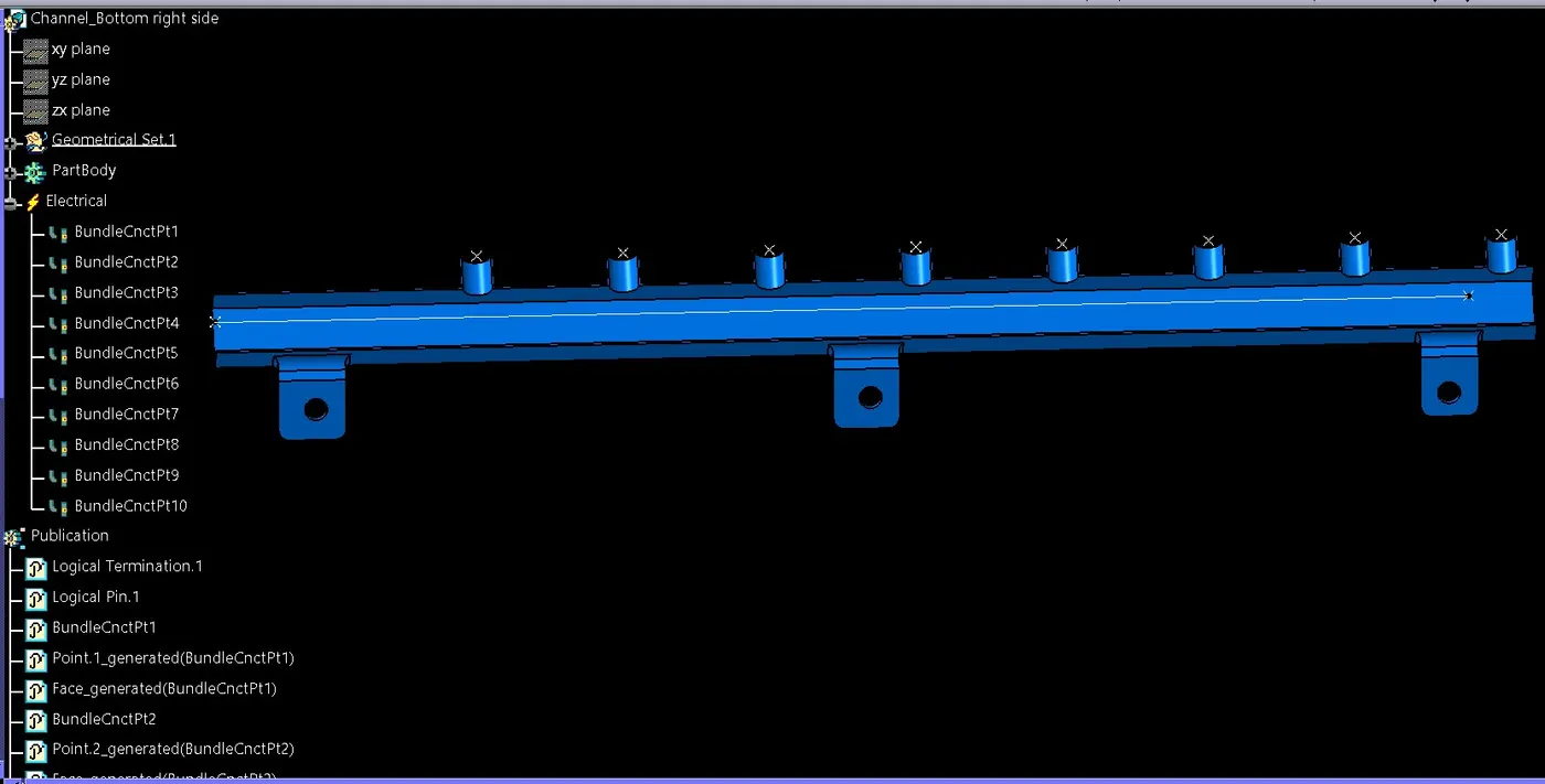
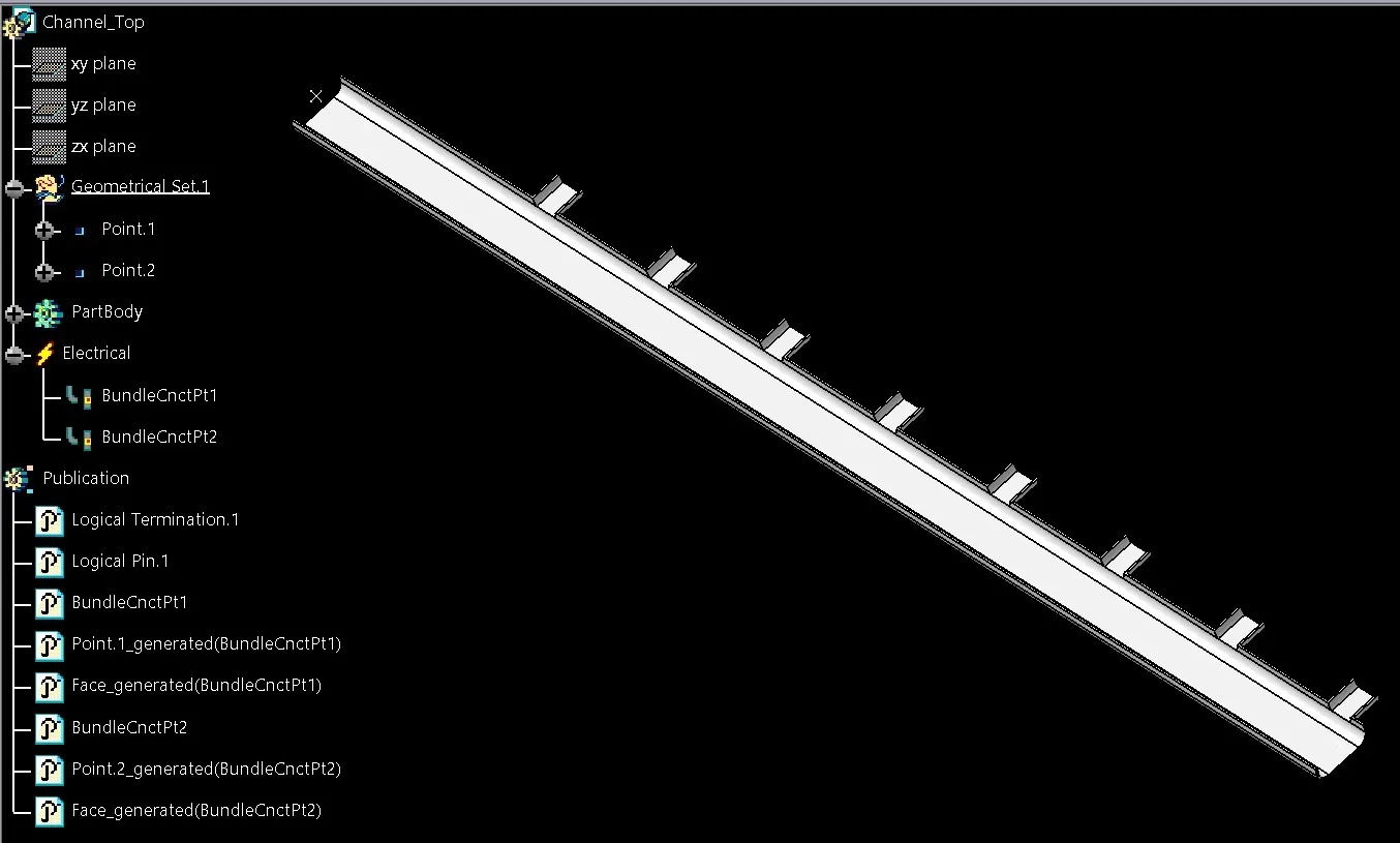
CONVERT THE GUIDED CHANNEL AS ELECTRICAL PART
GUIDED CHANNEL BOTTOM
GUIDED CHANNEL TOP
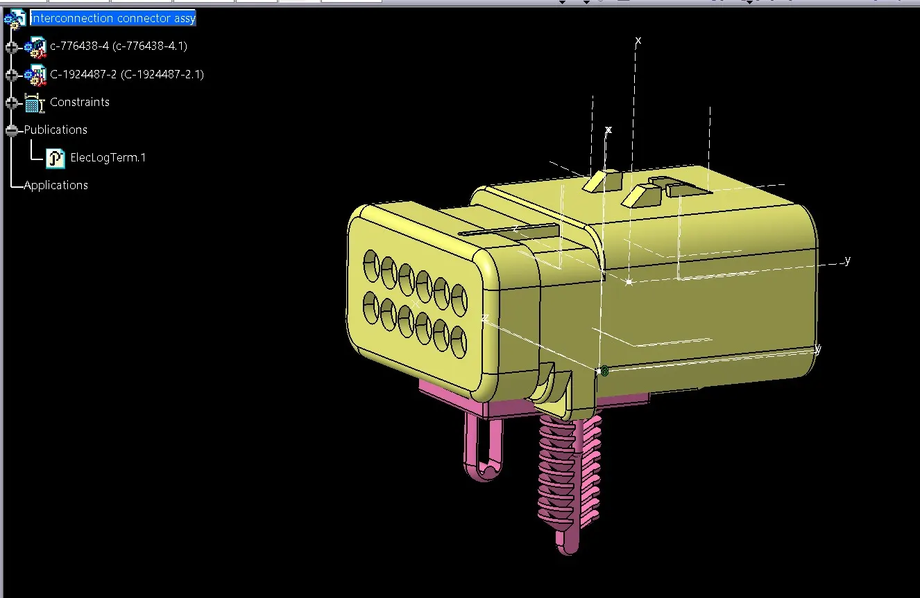
create new product file for inter connection connector and mounting clip 1924487-2 assembly
click on geometrical bundle command to make this assembly electrically
insert both the part and connect them electrically by using command connect electrical devices
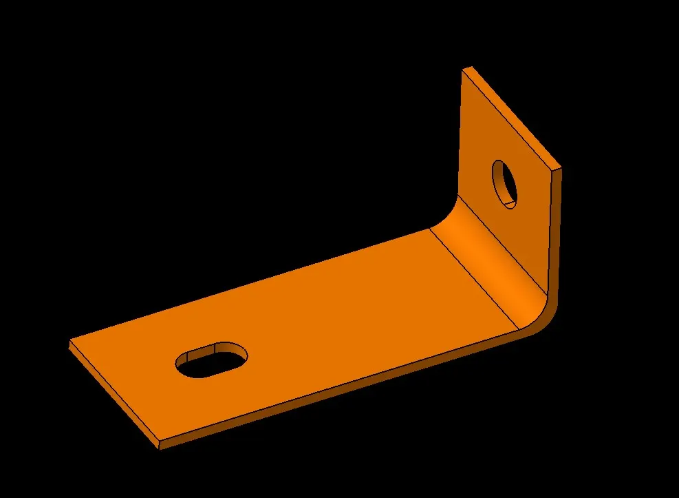
DOWNLOAD L-CLAMP SUPPORT
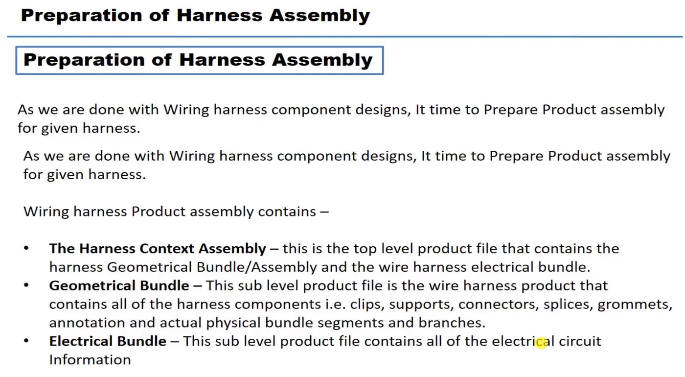
Creating the context assembly
select new-product- name this product as assy_engine harness_context
in this assembly insert given engine assembly and L-clip
now create another new product inside th context assembly and name it wiring harness_geometrical bundle
inside geometrical bundle assy insert all the electrically converted parts such as connector,clips,guided channels
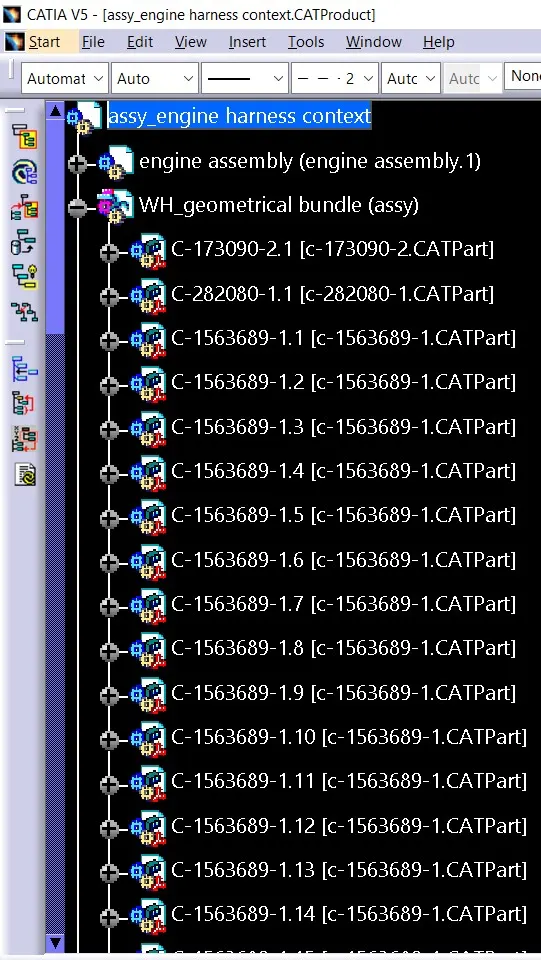
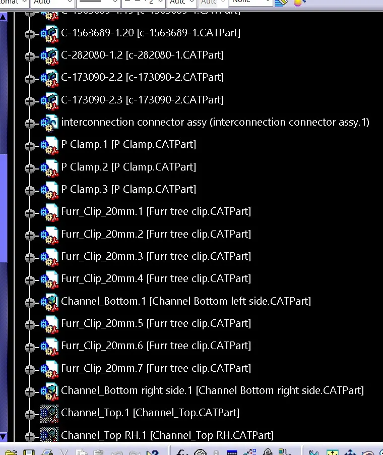
Some important packaging rules and best practices to be considered during wire harness routing and placing of the clips and clamps are as follows –
- Distance between two clamps on a straight branch should be minimum of 200mm.
- The minimum branch length should be 50mm.
- Minimum distance between clip and nearest branching point should be 25mm.
- The minimum distance between two straight connection points should be 200mm
- The minimum distance between two breakout points should be 50mm.
- To limit the number of branches from a single branch point to 4.
- Avoid routing wiring harness near the exhaust manifold and its components and also from other unshielded heat sources. If re routing is not possible then maintain a minimum distance of 200mm.
- Try to avoid use of too many metal brackets on engine. Try to use the available threaded bosses on engine or demand for it.
- Enough clamps shall be provided to ensure positive clearance with surroundings and safety of wiring harness.
- P - Clamps, Fir tree clips and other clips can be added to the Geometric bundle as they are electrically defined and are part of the Wire harness routing and should be provided with the Wire bundle package.
- Enough slack should be provided to the wiring harness which help not to get damaged during the Engine rocking or starting condition.
- The wire harness routing should be done in such a way that it is easy in manufacturing and serviceability.
- The wire routing should be done keeping in mind the cost effectiveness of the bundle package.
- To avoid the harness routing and clipping in blind zones of the operator during the assembly and the service.
- To provide proper slack at end connectors so that there will be no tension on the wire bundle.
- To avoid sharp edges on the sheet metal parts and if it is not possible then provide protection parts to prevent damage of the wire bundle.
- To provide separate branch points for separate connectors to ensure Poka-Yoke.
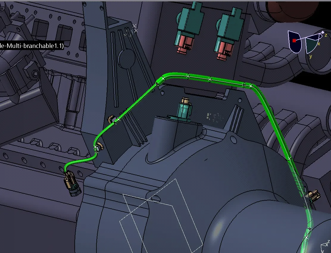
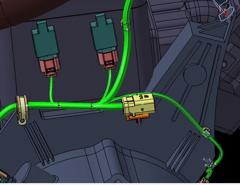
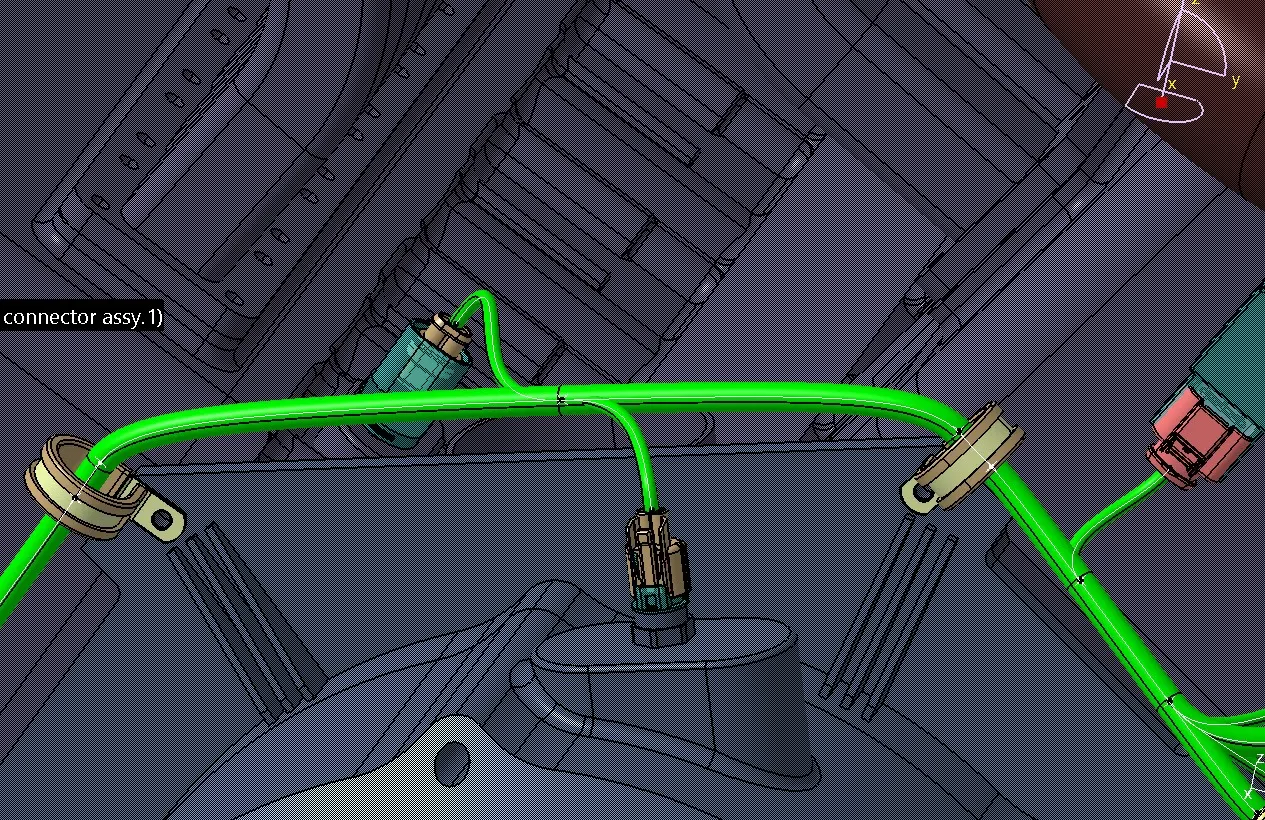
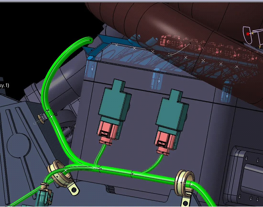
Keeping all the above packaging rules we can start the routing of the wire and provide clipping and clamping wherever necessary during the routing process.
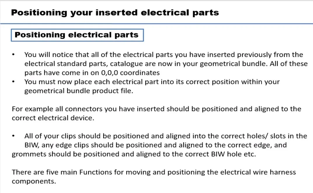
position all the above mention connectors on their desire location
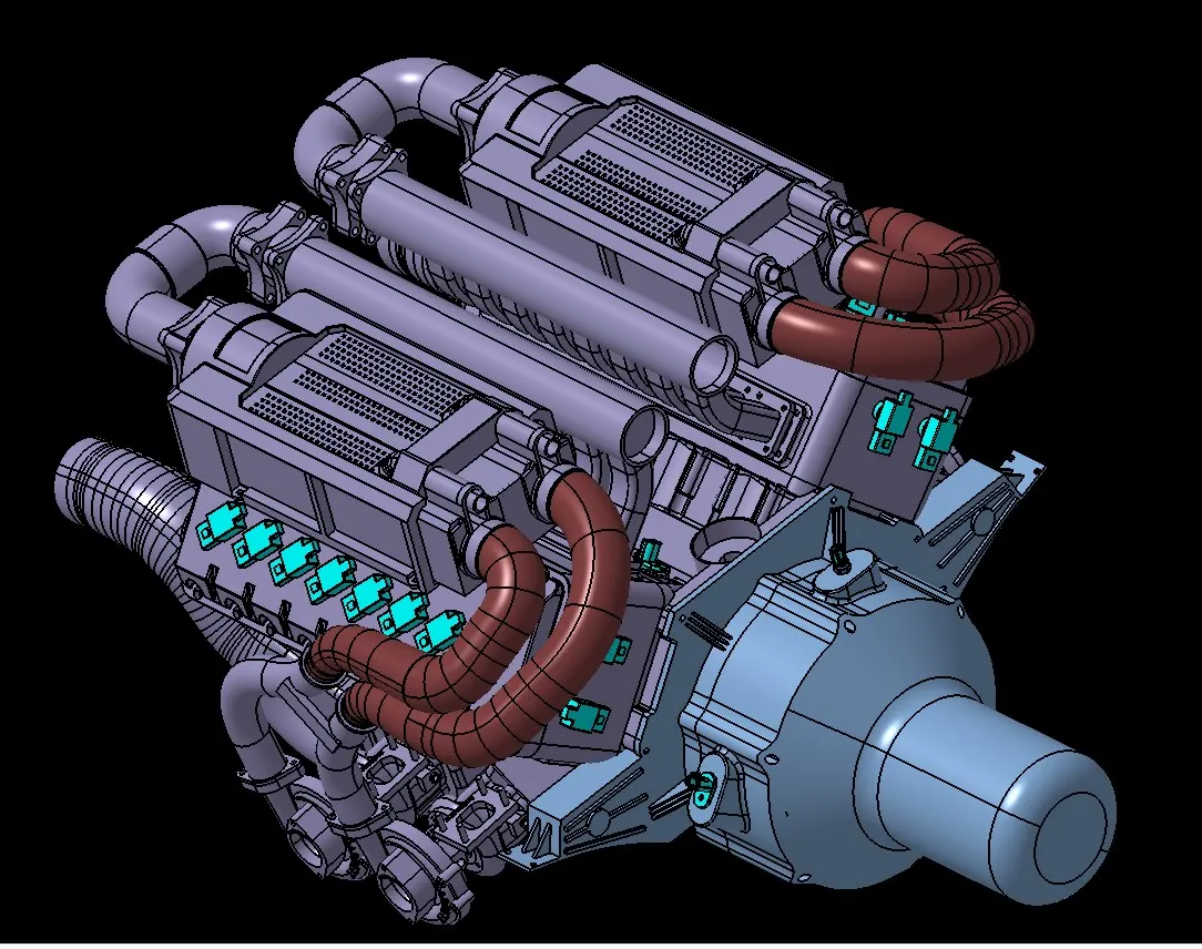
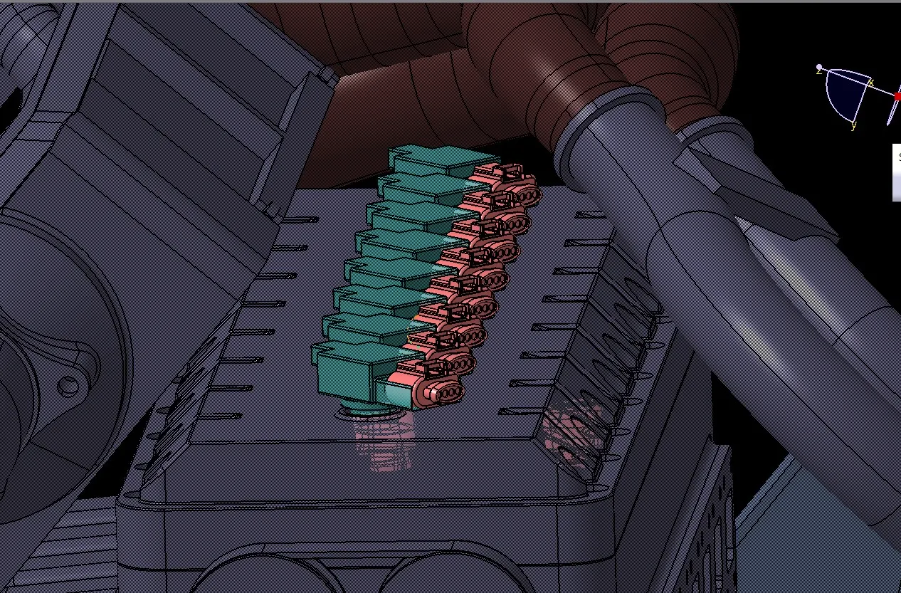
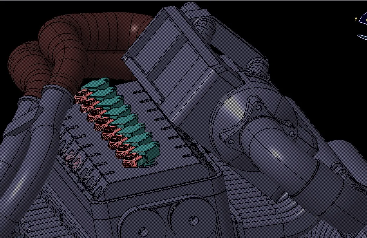
The Given V16 engine 3D-CAD model requires a total of 25 connectors to be placed on it and an inter connection connector for the engine wiring harness assy. The connectors used in this engine are as follows
- 8 numbers of connectors are required on the fuel injector sensors on each cylinder head, i.e.; total 16 fuel injector sensor connectors are needed.
- Total 4 numbers of cam-shaft sensor connectors are
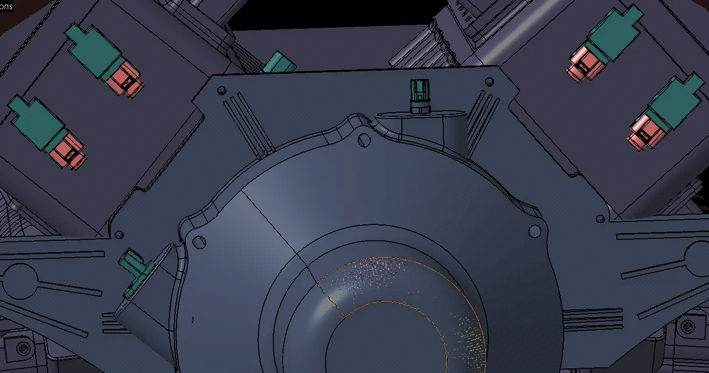
- 1 neutral position sensor connector and 1 speed sensor connector
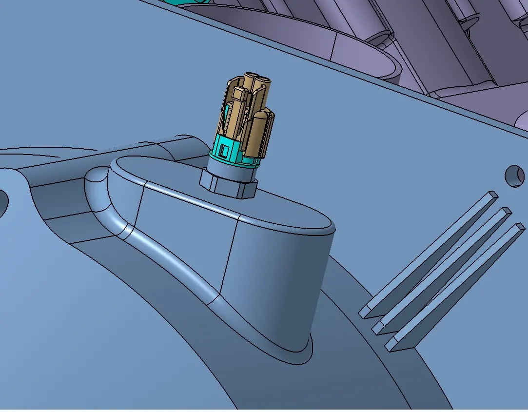
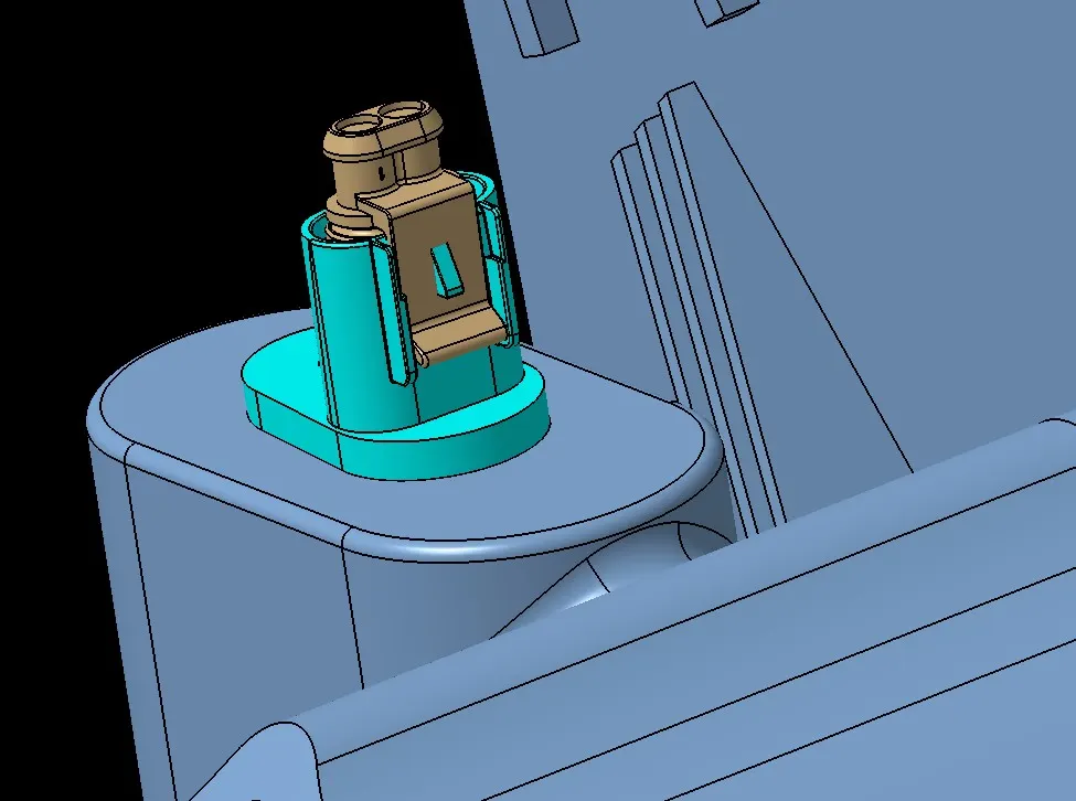
- 1 engine coolant temperature sensor connector
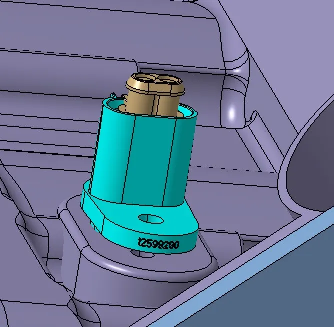
- 2 oil sump temperature sensor connector
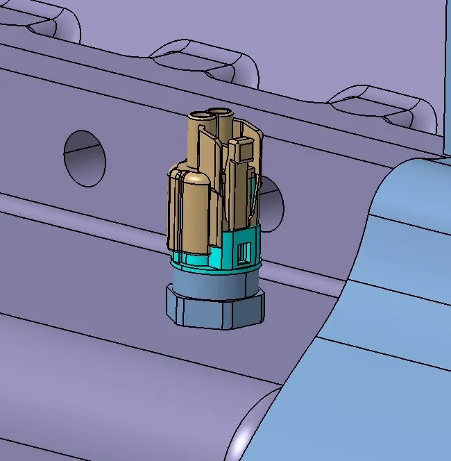
guided channel positioning
p clamp positioning
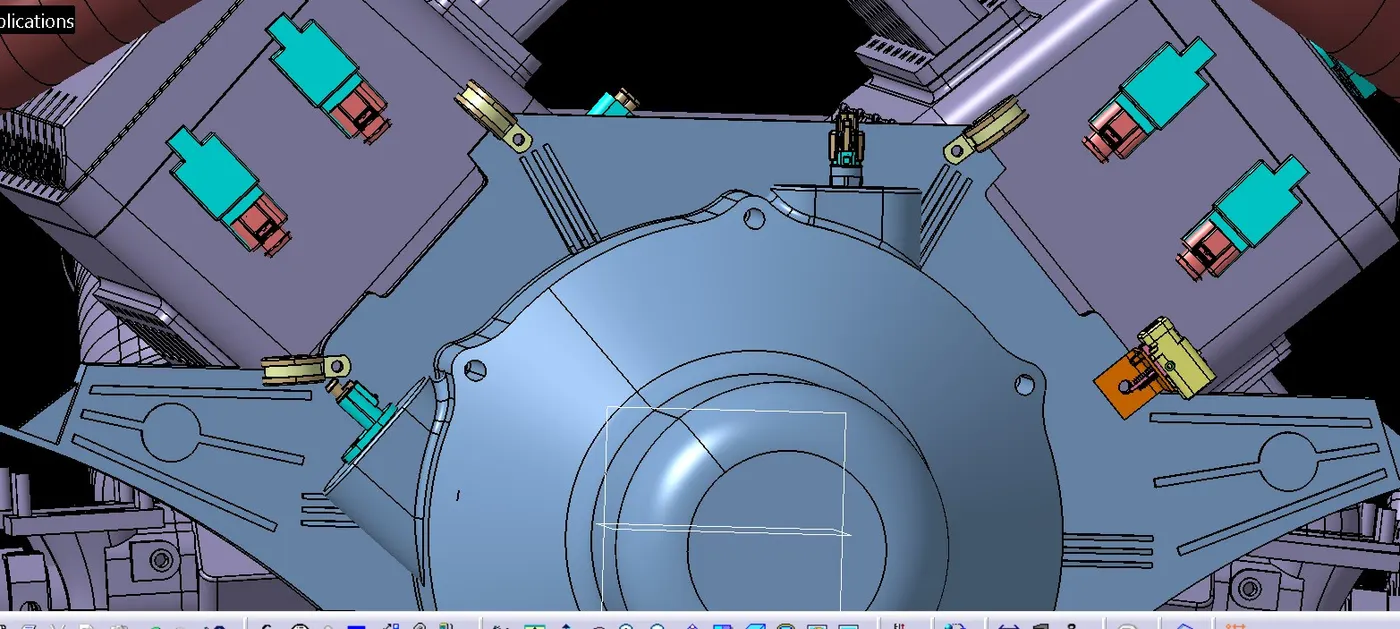
fir tree clip positioning
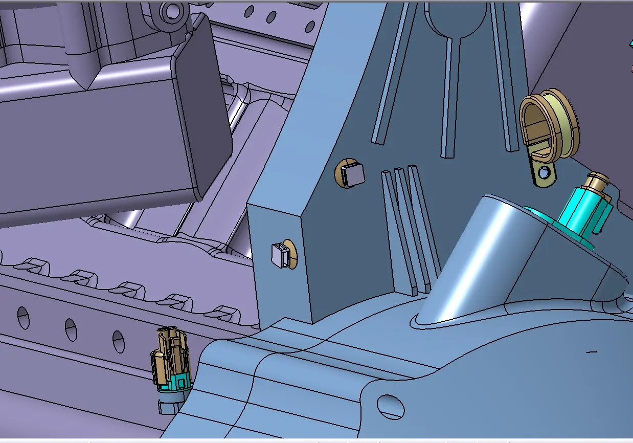
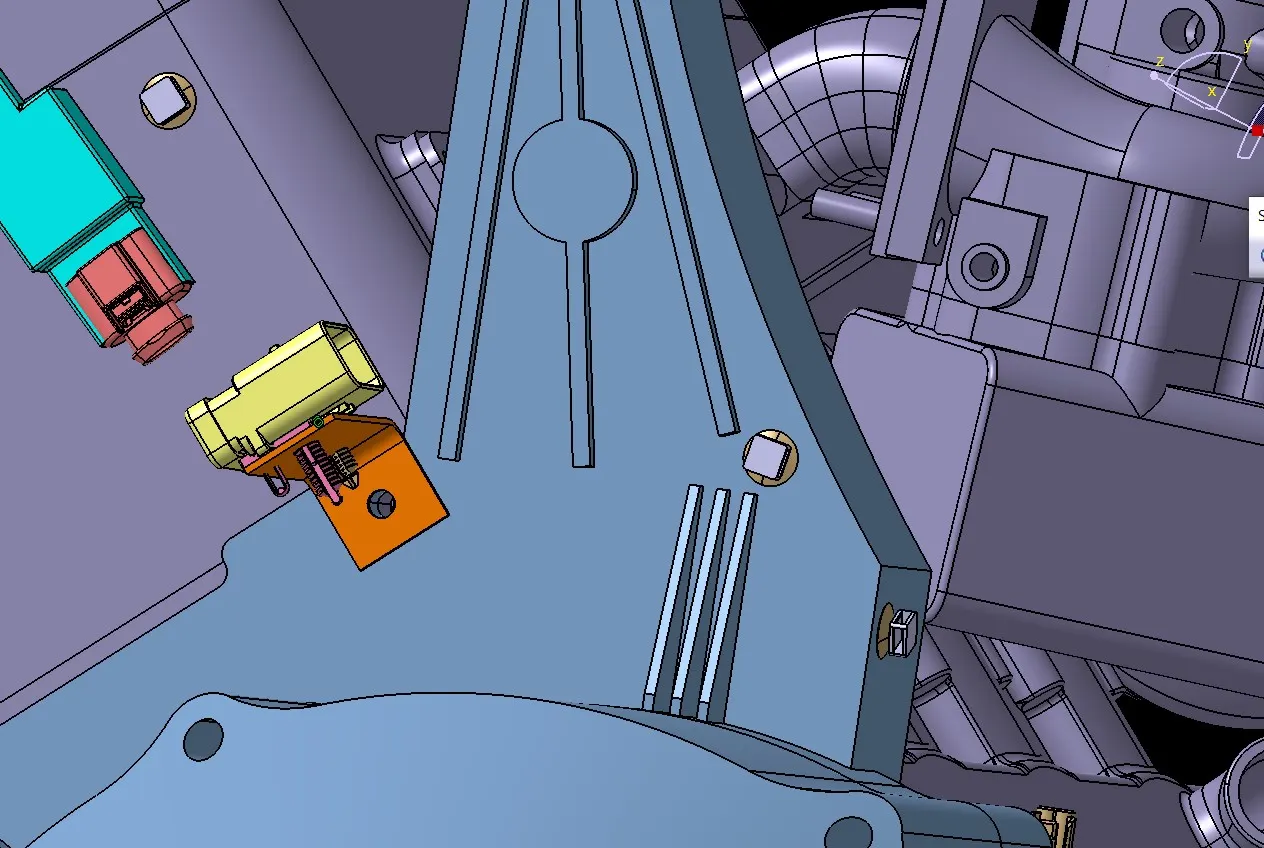
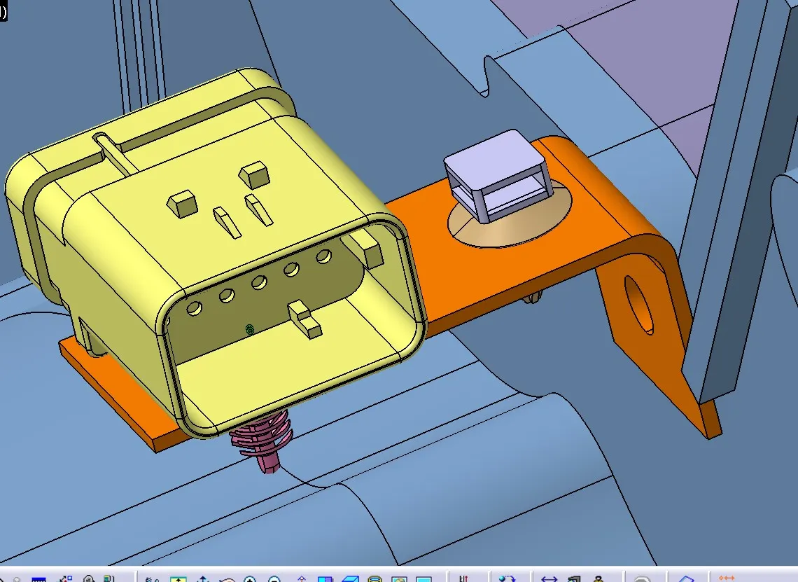
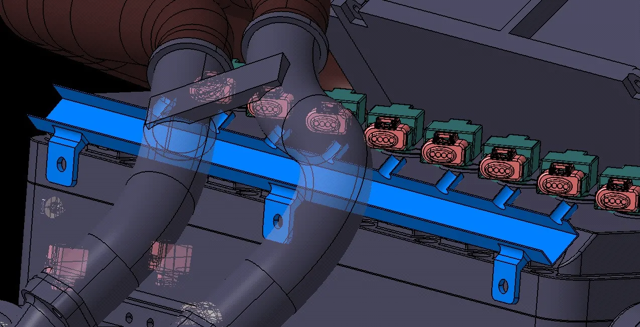
positioning of interconnection connector and L-CLAMP
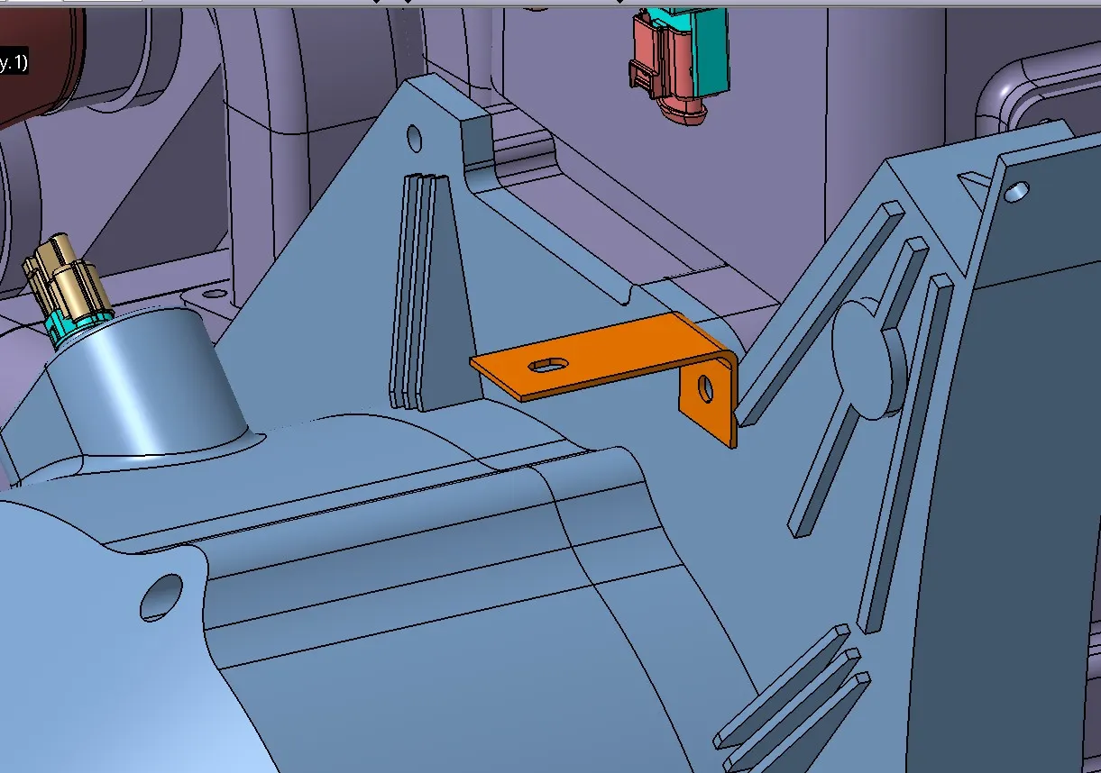
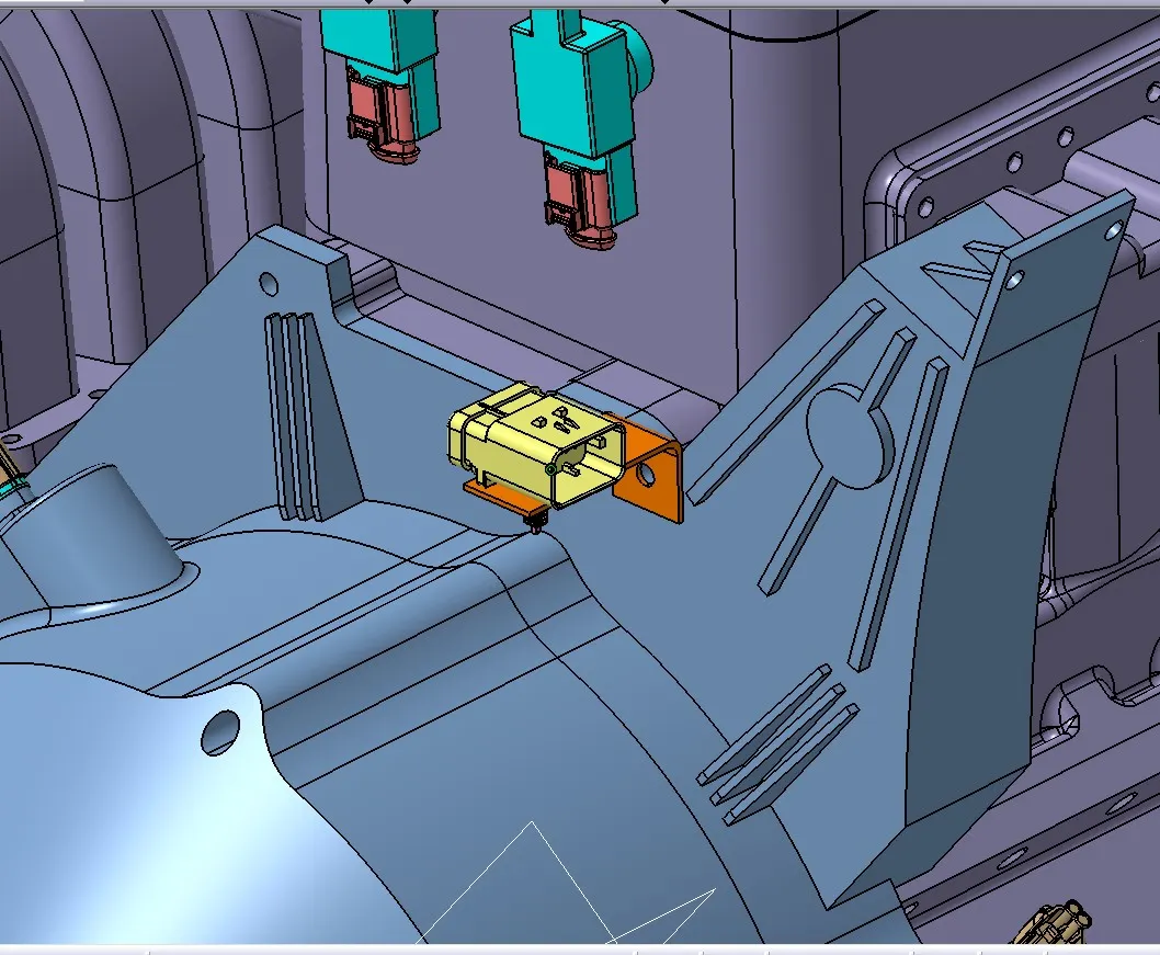
convert the geometrical bundle assembly as an electrical assembly by using command geomterical bundle
Wiring Harness Routing
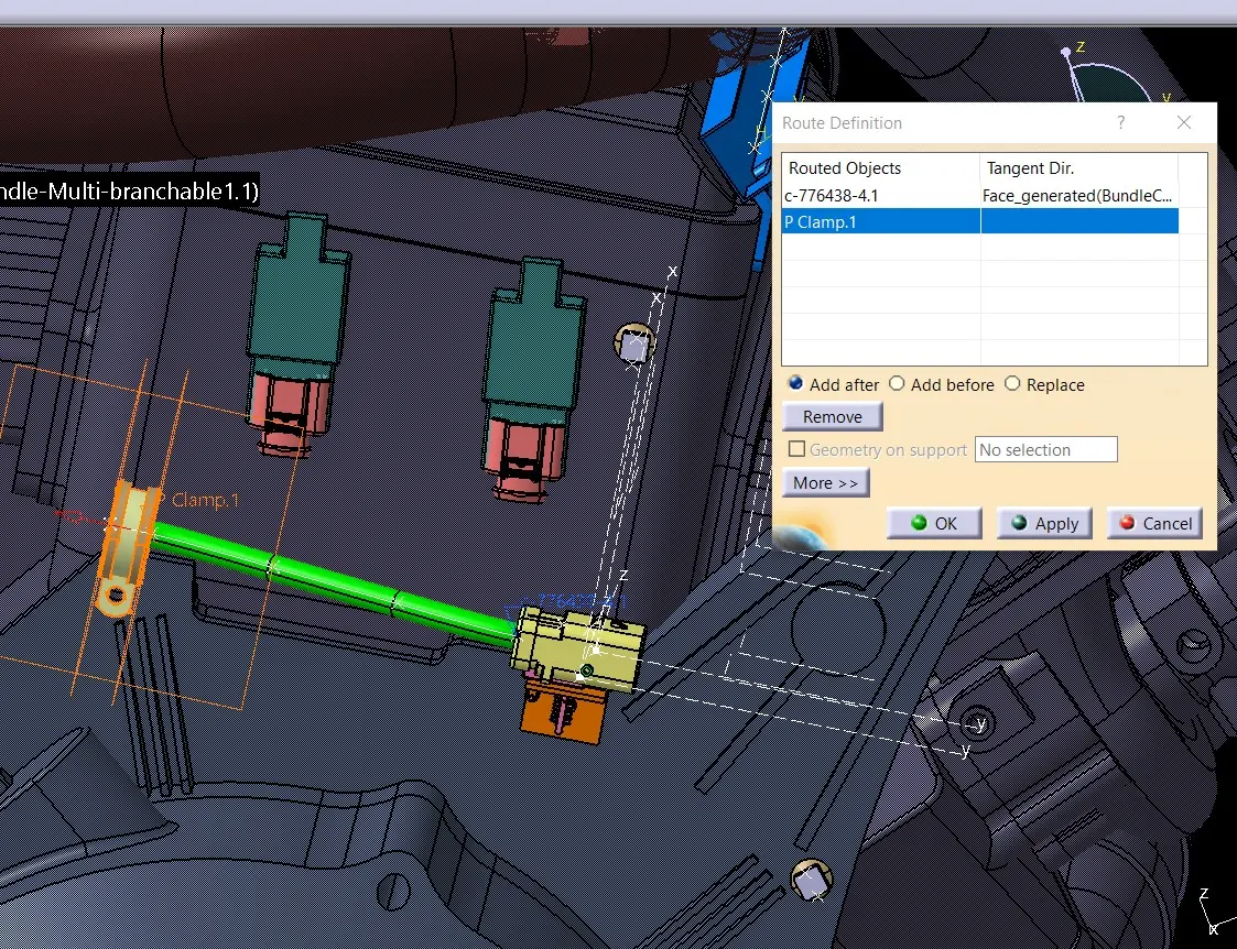
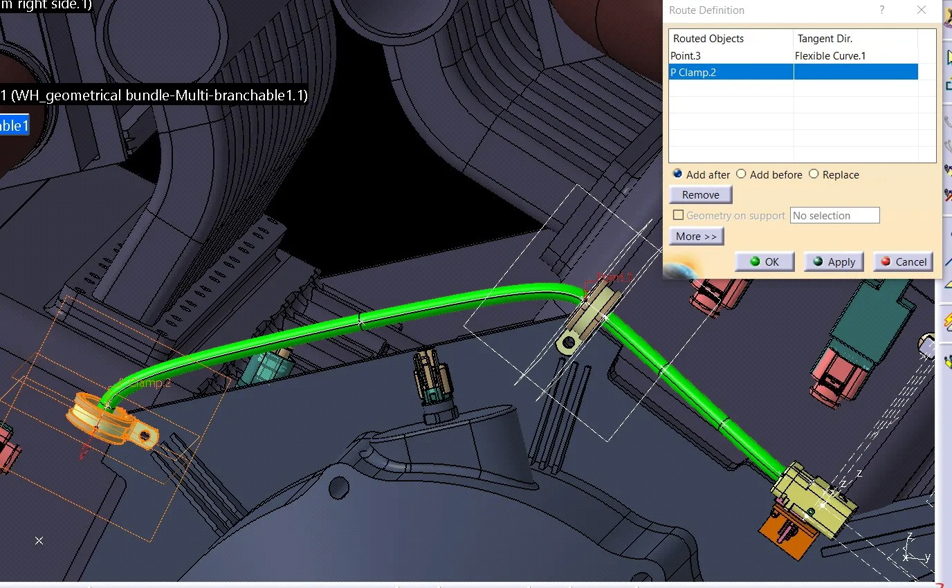
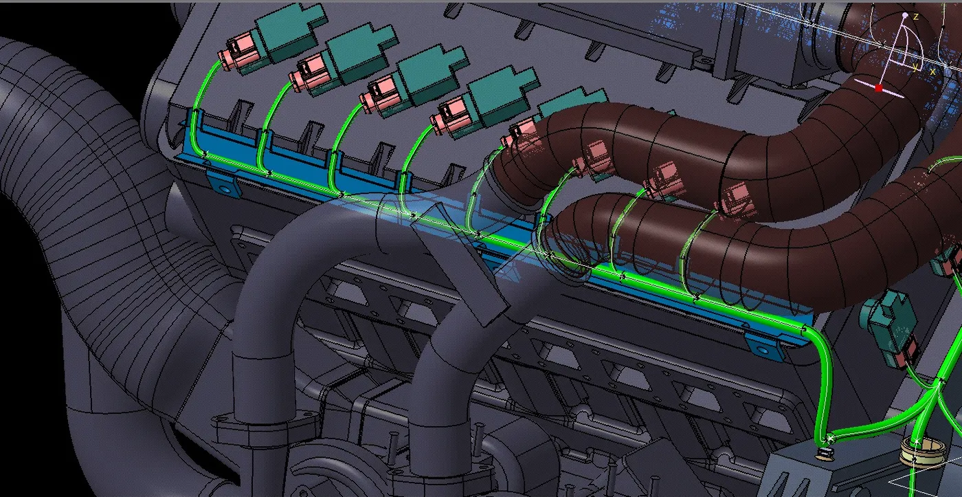
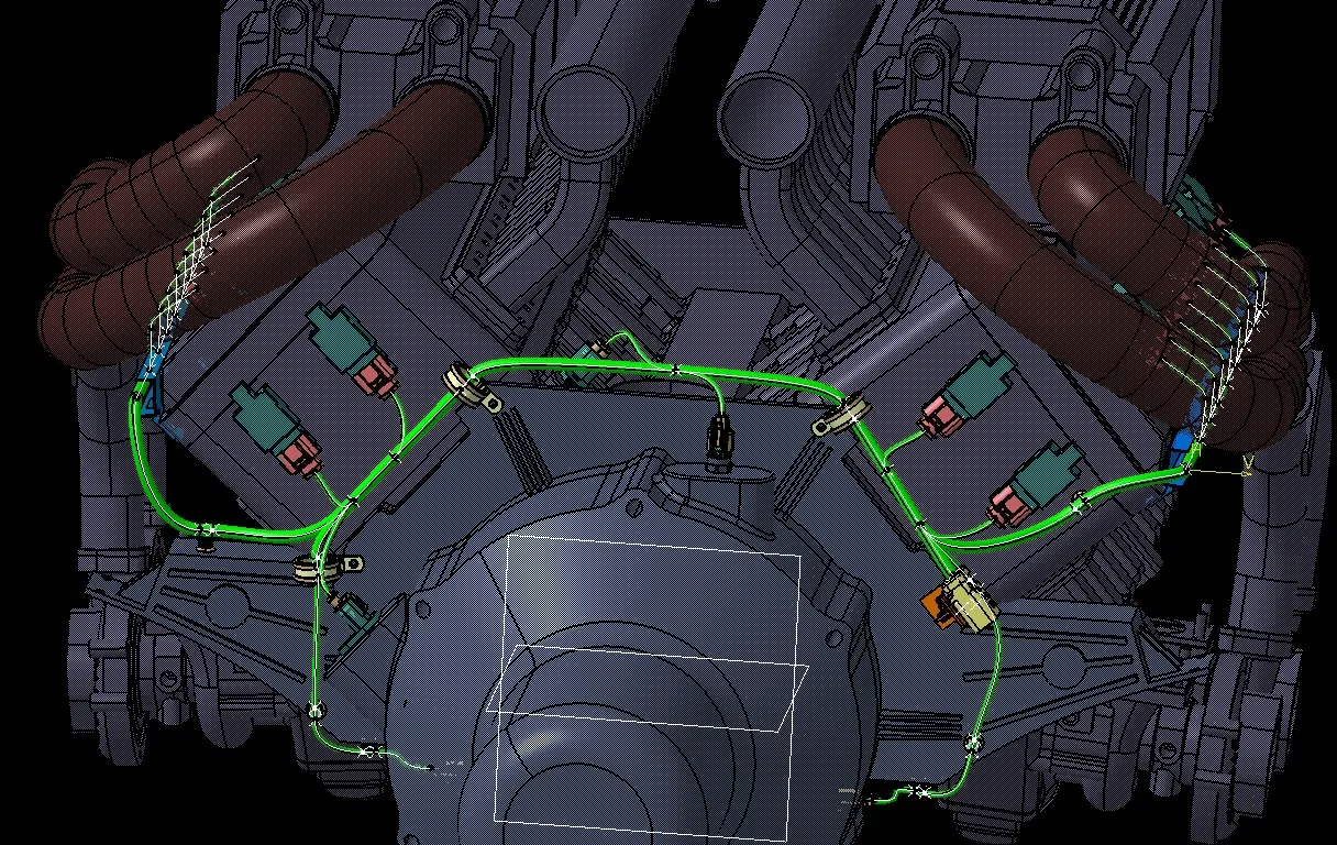
CHECK BUNDLE CONTINUITY
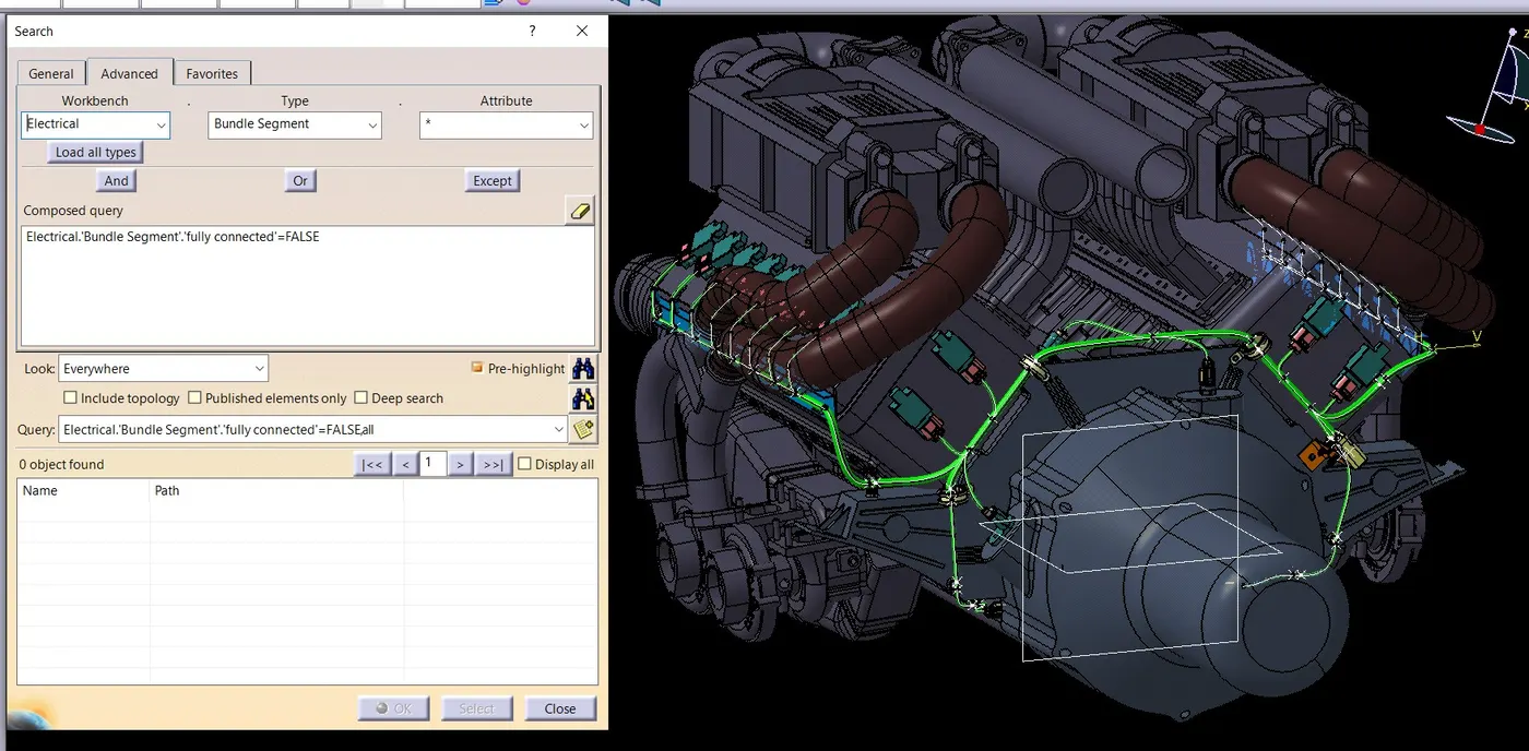
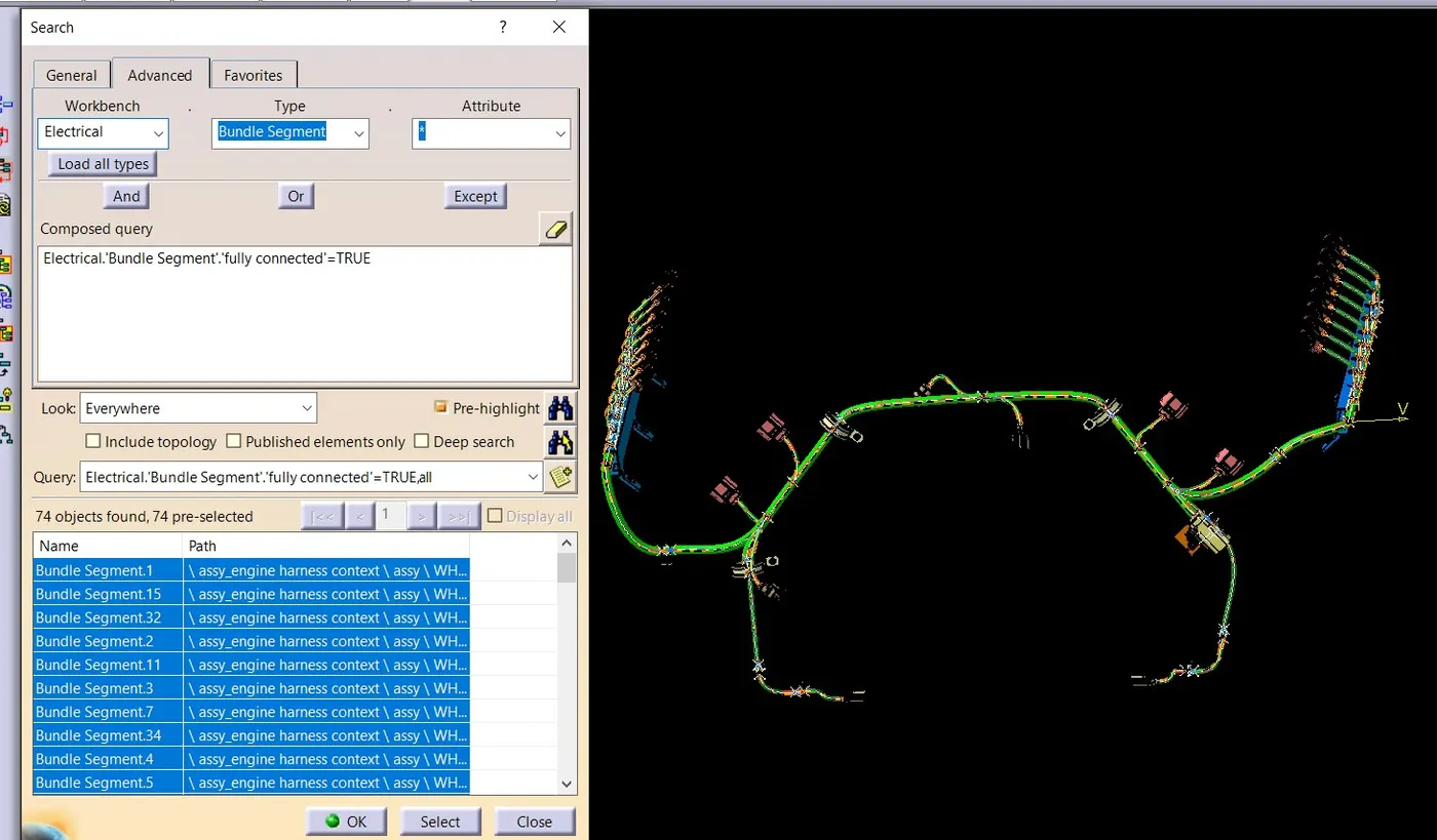
We need to ensure that the entire bundle is fully connected.
Go to edit and then click on search command.
Go to advanced
Select workbench as electrical, type as bundle segment and attribute as fully connected
The select result should be as TRUE or FALSE and the click search to see the connectivity analysis result
FALSE VALUE
TRUE VALUE
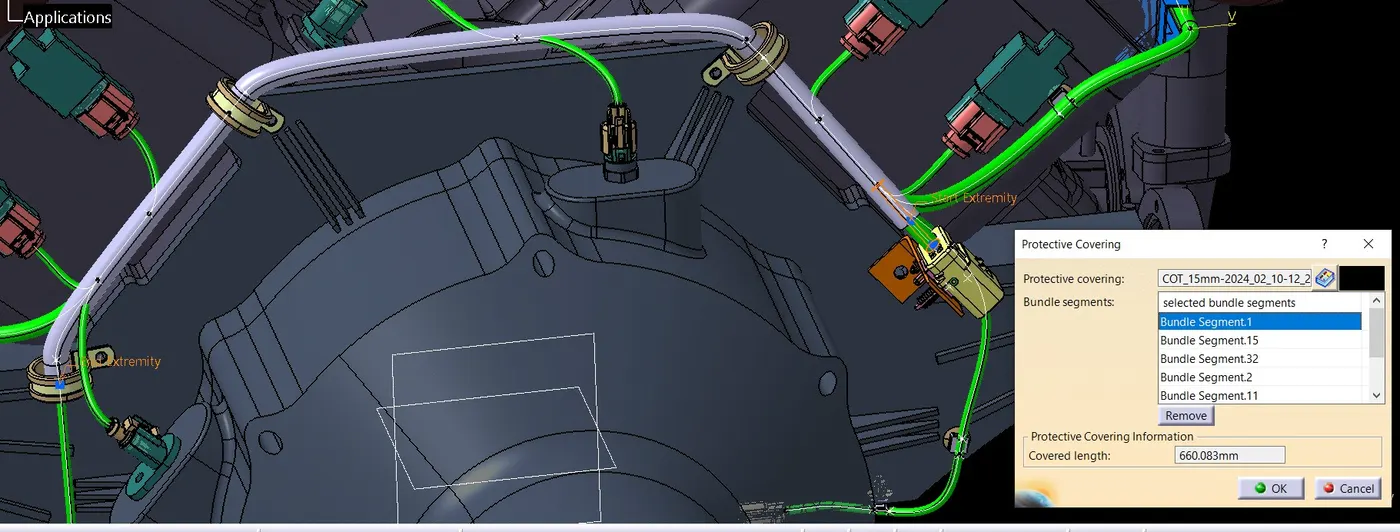
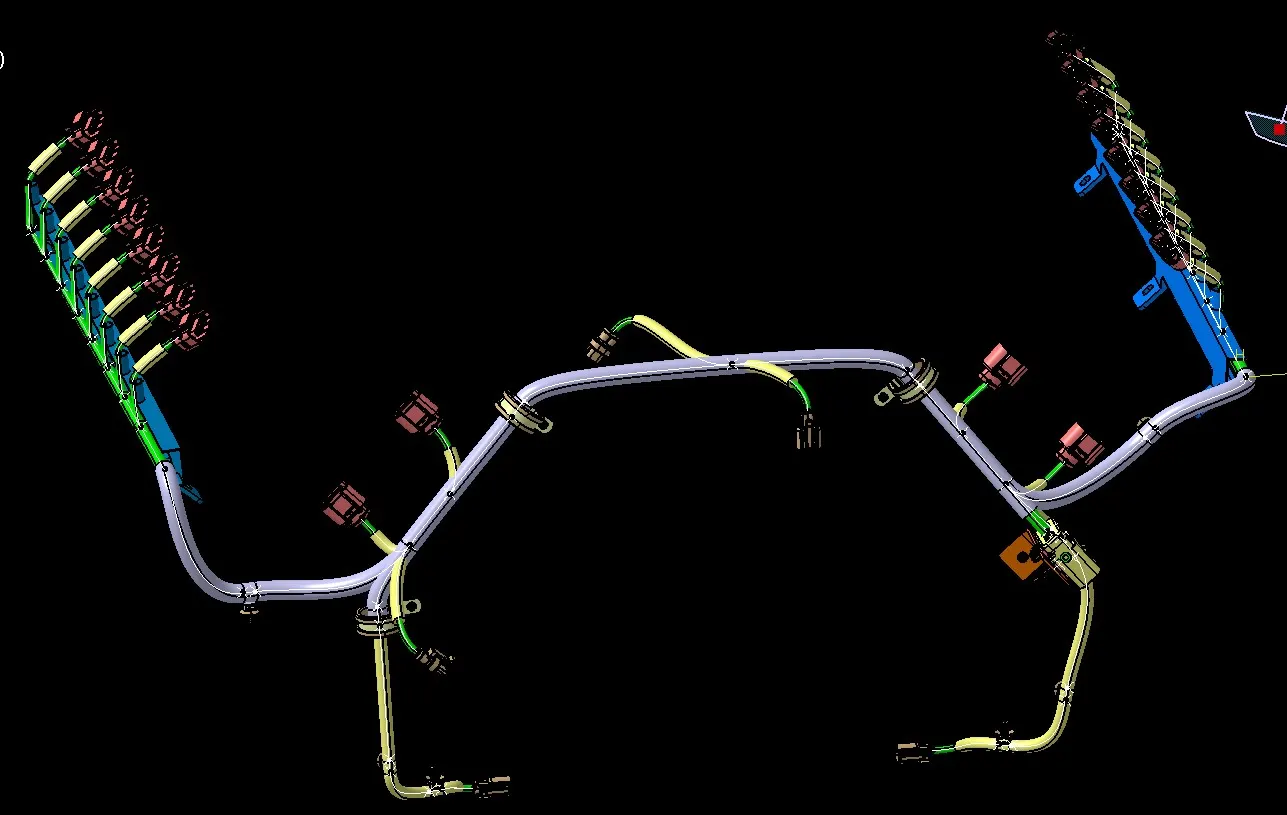
After finally completing the wire harness routing by following the packaging rules we need to provide protection covering to those parts wherever necessary
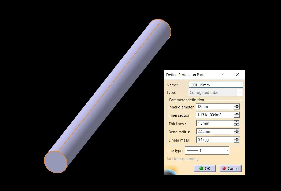
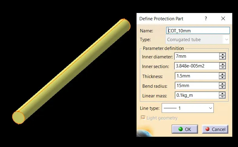
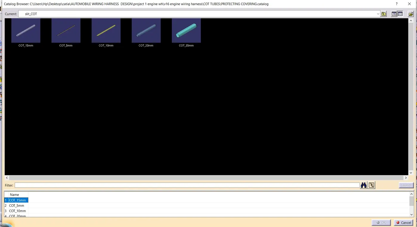
PROTECTION COVERING
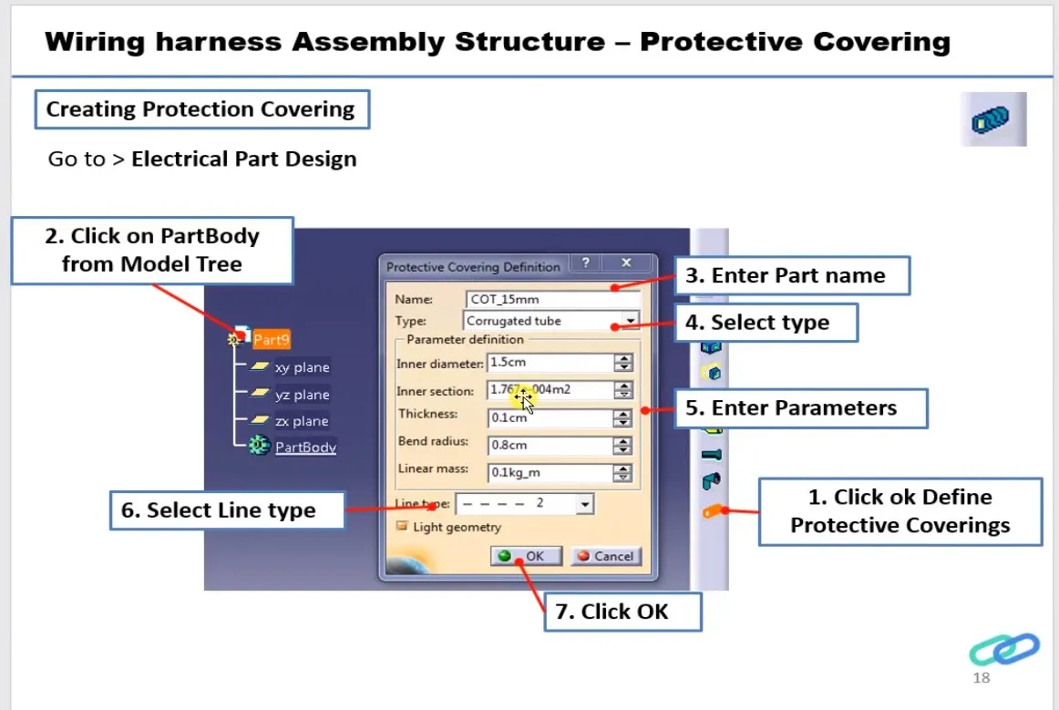
COT_15mm
COT_10mm
apply protective covering
WIRING HARNESS FLATTENING
- To create the Flattened Harness, we need to create a new product file and switch into the electrical harness flattening workbench.
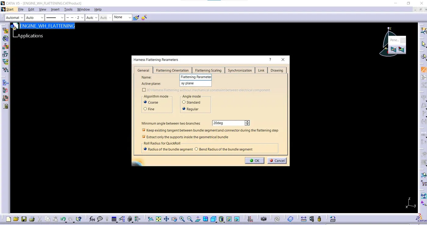
- Now we need to define the Harness Flattening Parameters and then Extract the geometric bundle from the wiring harness context product file.
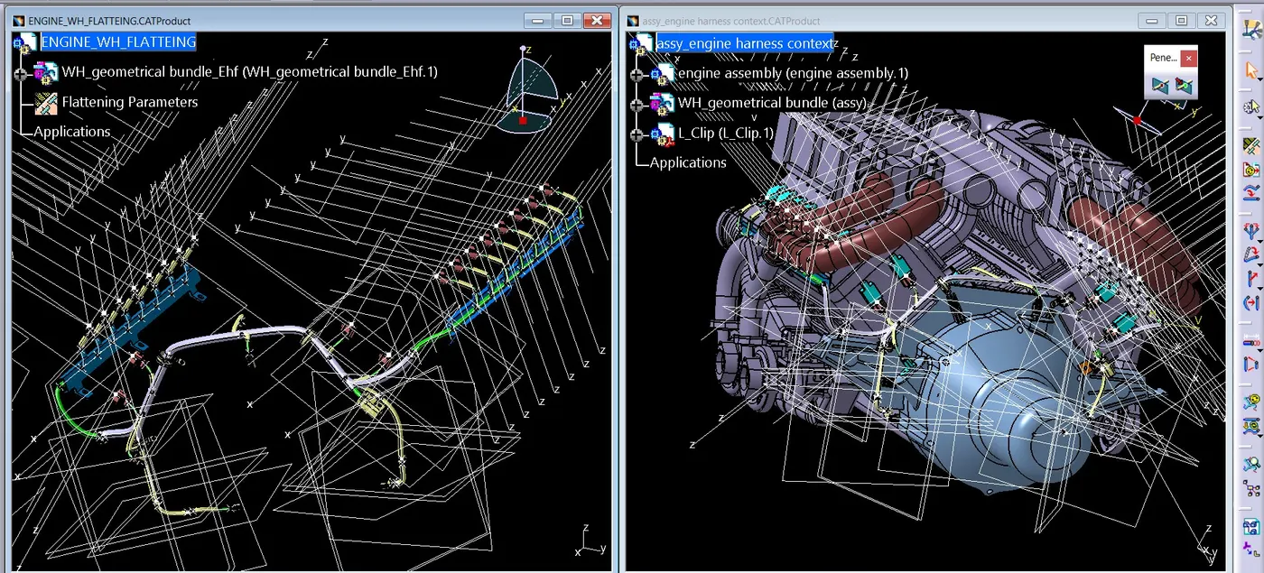
- Then select all the branches and flatten the entire Geometric bundle.
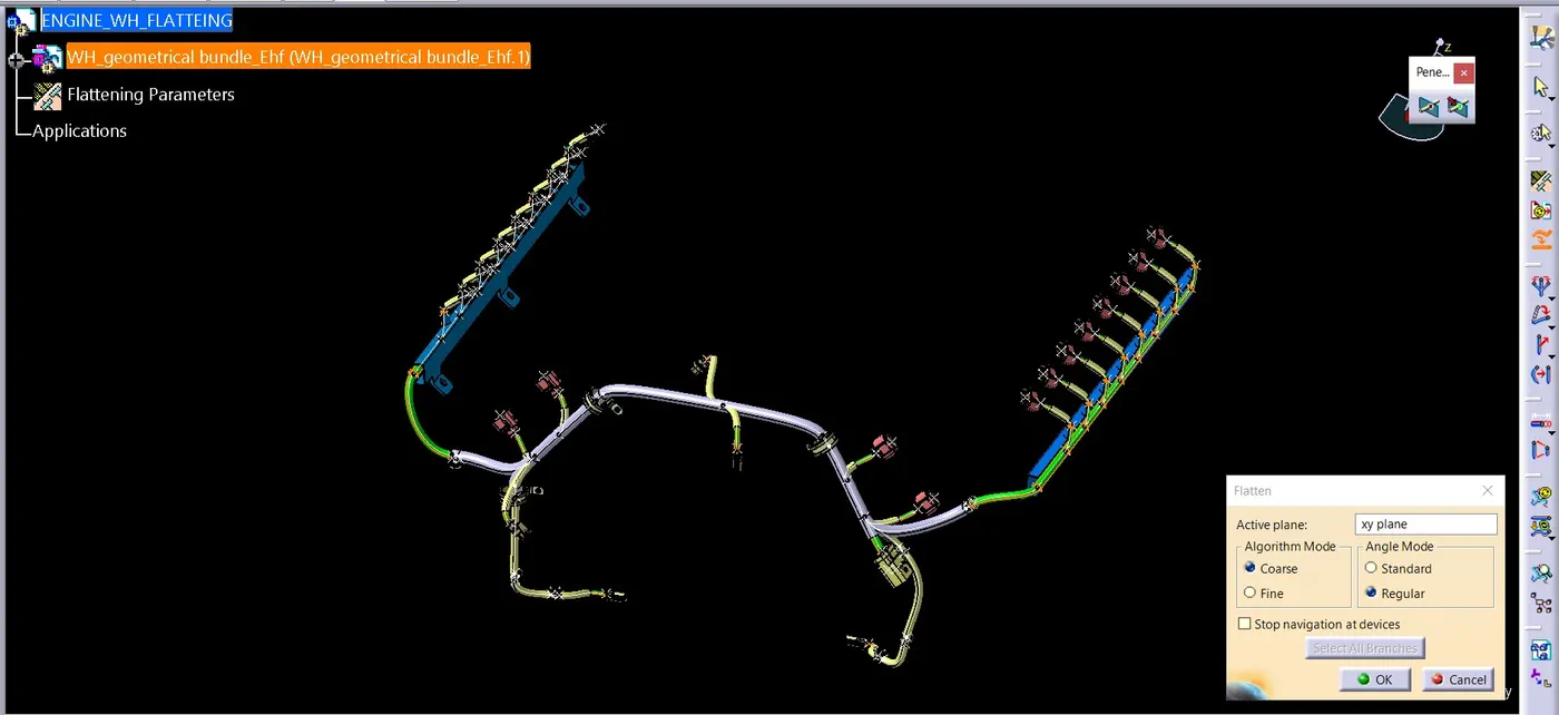
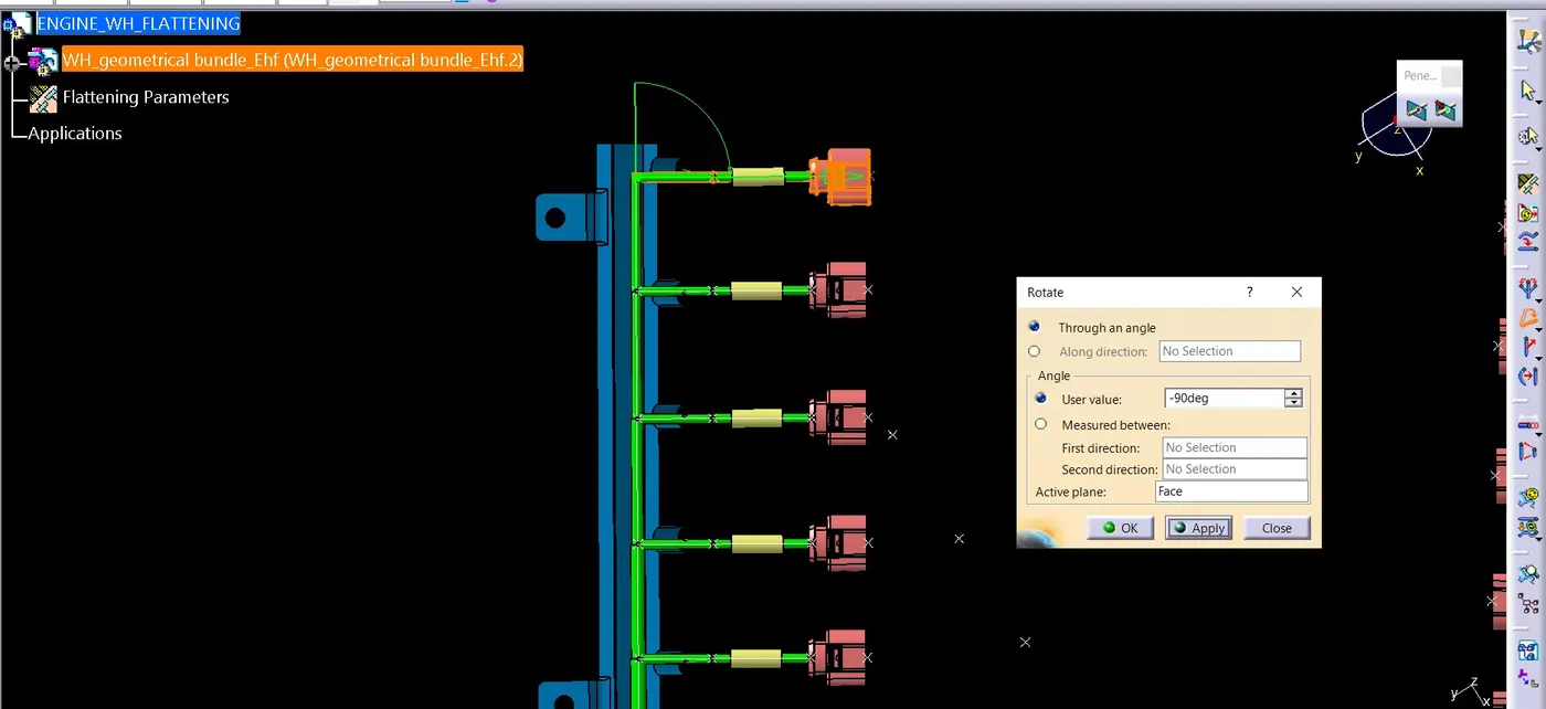
Rotate the flattened bundle segments to the desired directions using the rotate command and manually update the product to update the changes occurred during the rotate command.
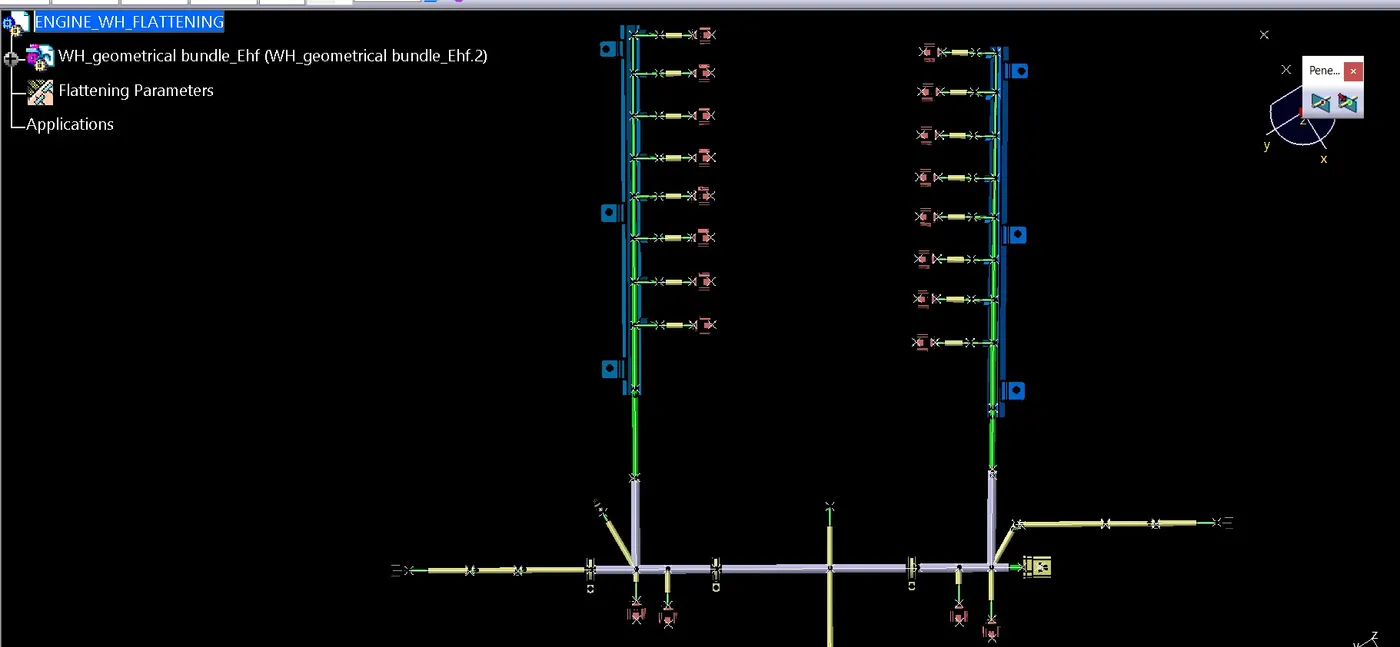
Create a Drawing File for the flattened harness product.
First, we need to make sure that in the flatten parameter settings bundles and protective coverings have different graphical representation which are,
Bundle Segments – Single line representation
Protective coverings – Double line representation.
Create a new drawing file in the drafting workbench
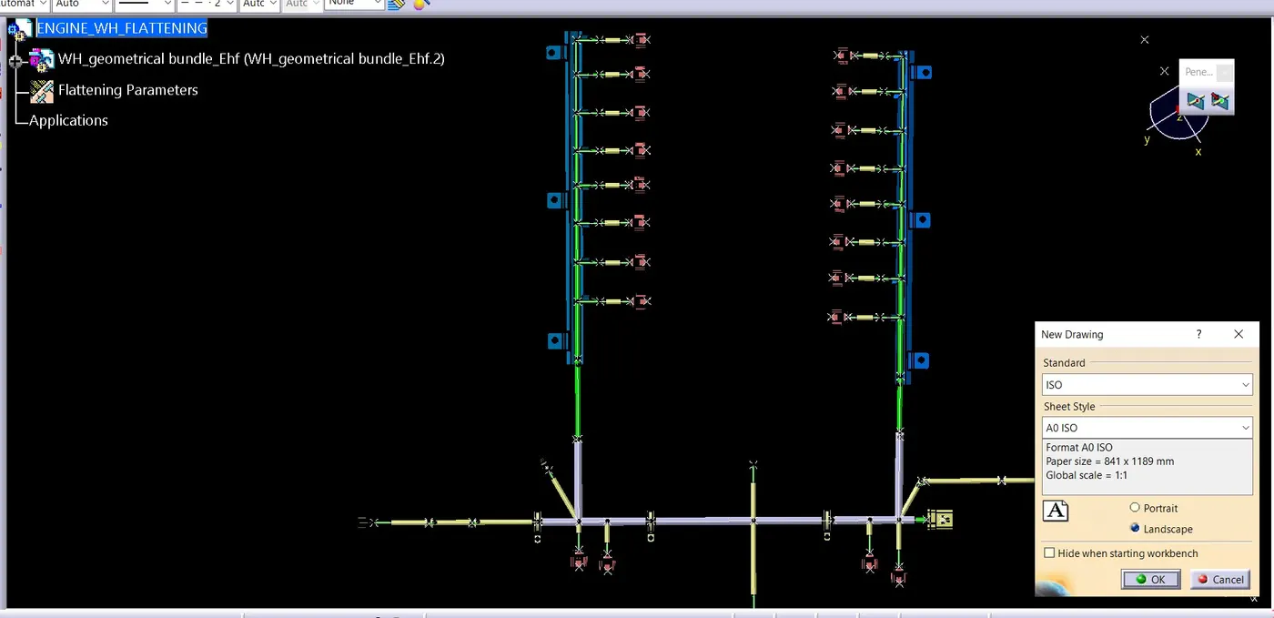
Modify the drawing sheet with required parameters.
Insert the flattened harness product into the drawing sheet using view option and selecting the front view command.
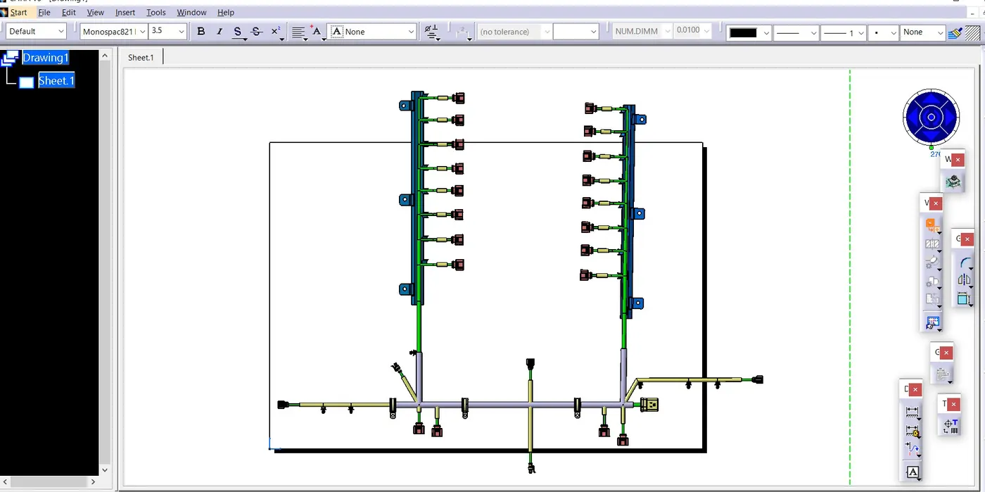
We can see the drawing representation for the wiring harness bundle is not visible in the drawing sheet. Here, we need to change some settings in sheet properties.
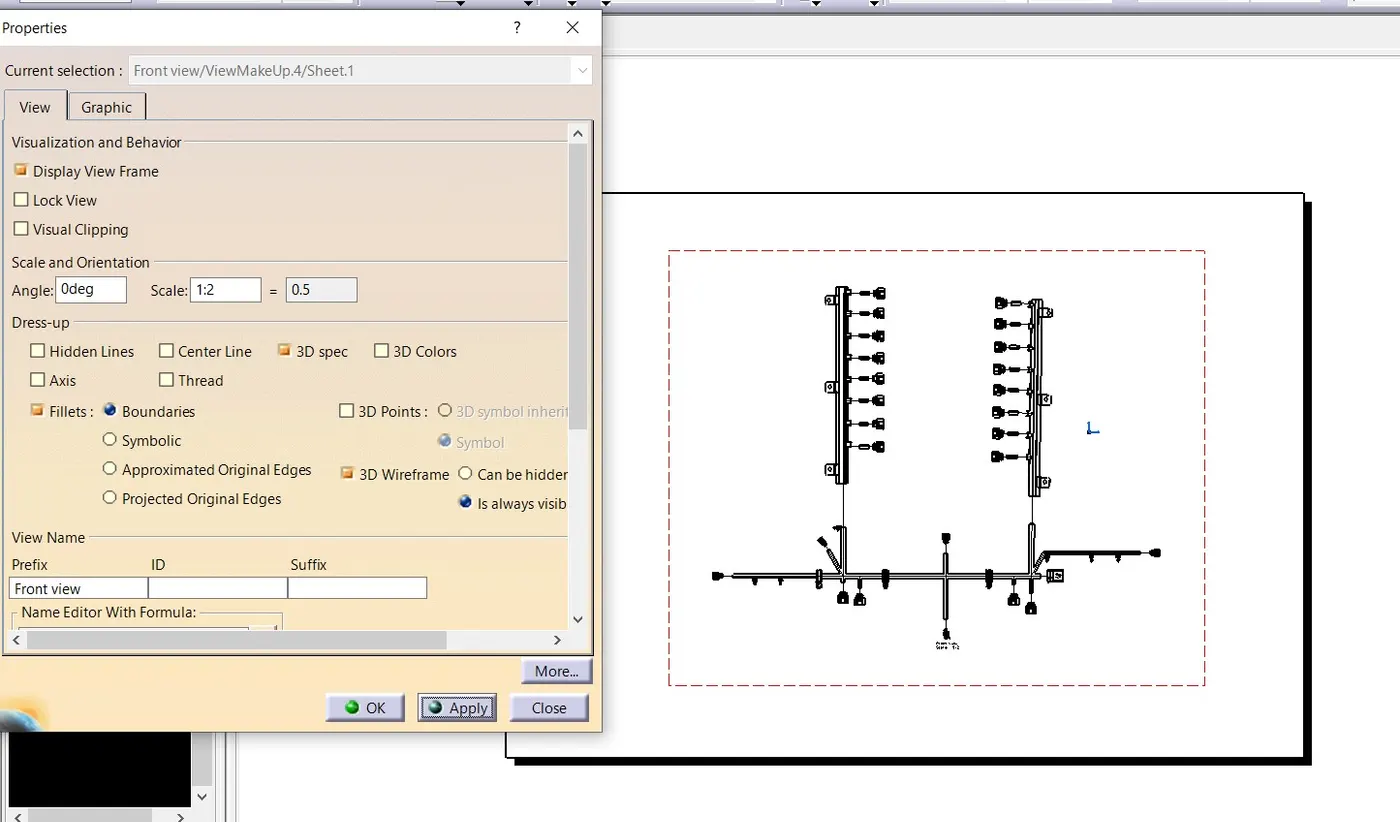
In sheet>front view properties, go to the views and dress-up area, activate the 3D wireframe and change it into always visible and click OK.
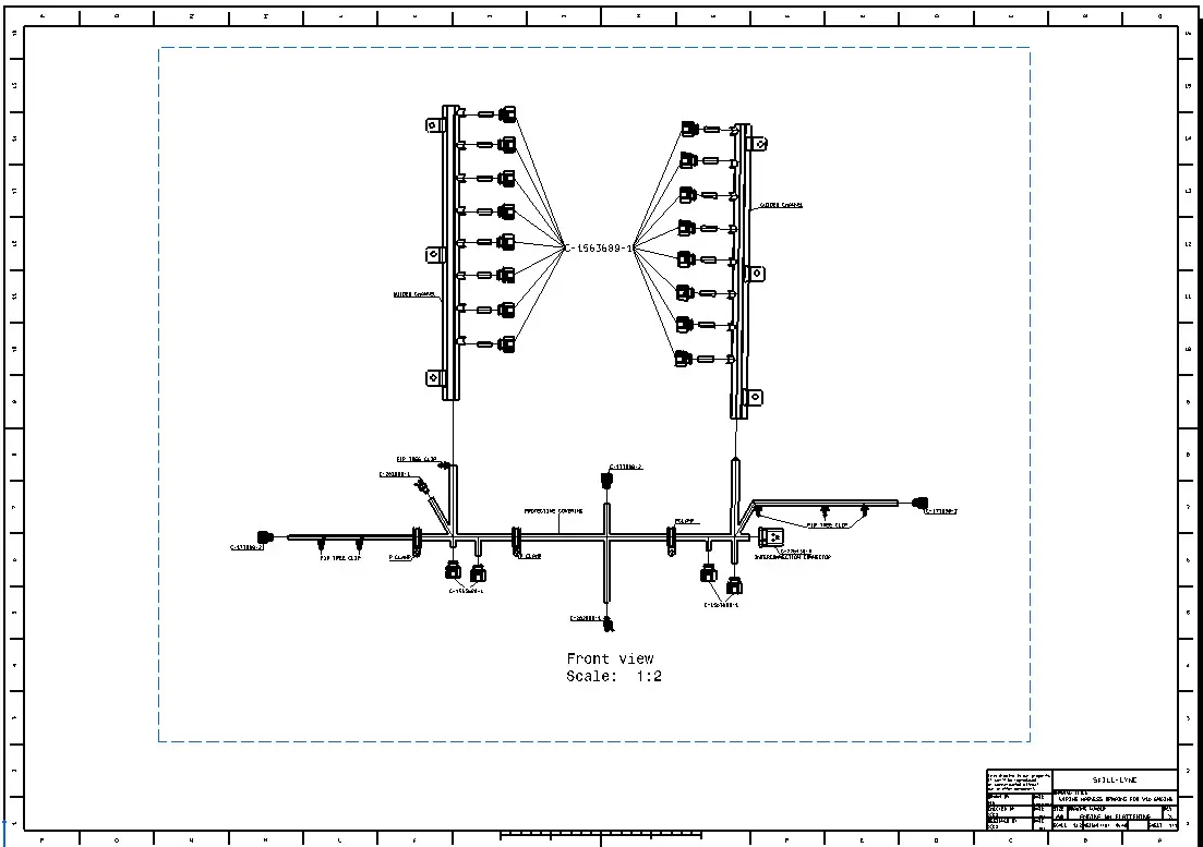
PROJECT-1 FILE
https://drive.google.com/file/d/1XET8iQicDTG6A59hJvO2avJpucb2o5Wh/view?usp=sharing
(not able to attach file)