Project 1 - 1d modelling of liquid cooling system
Project:1
Objective:1D Modelling of Liquid Cooling System.
Model a cooling plate mounted with 2 modules made up of several cells. The flow pattern is as indicated in the picture. Use water as the coolant, flowing from a tank of limited capacity.
- Plot top and bottom module temperatures.
- Analyze the change in battery and coolant temperature with tank capacity.
- Analyze the change in battery and coolant temperature with coolant flow rate.
Solver settings: Automatic fixed step solver with 1s timestep.
Theory:
Which cooling system works best in Electric Vehicles?
Battery thermal management systems are still a highly researched topic, and what we know about them is going to change and develop over the coming years as engineers continue to rethink how our car engines work.
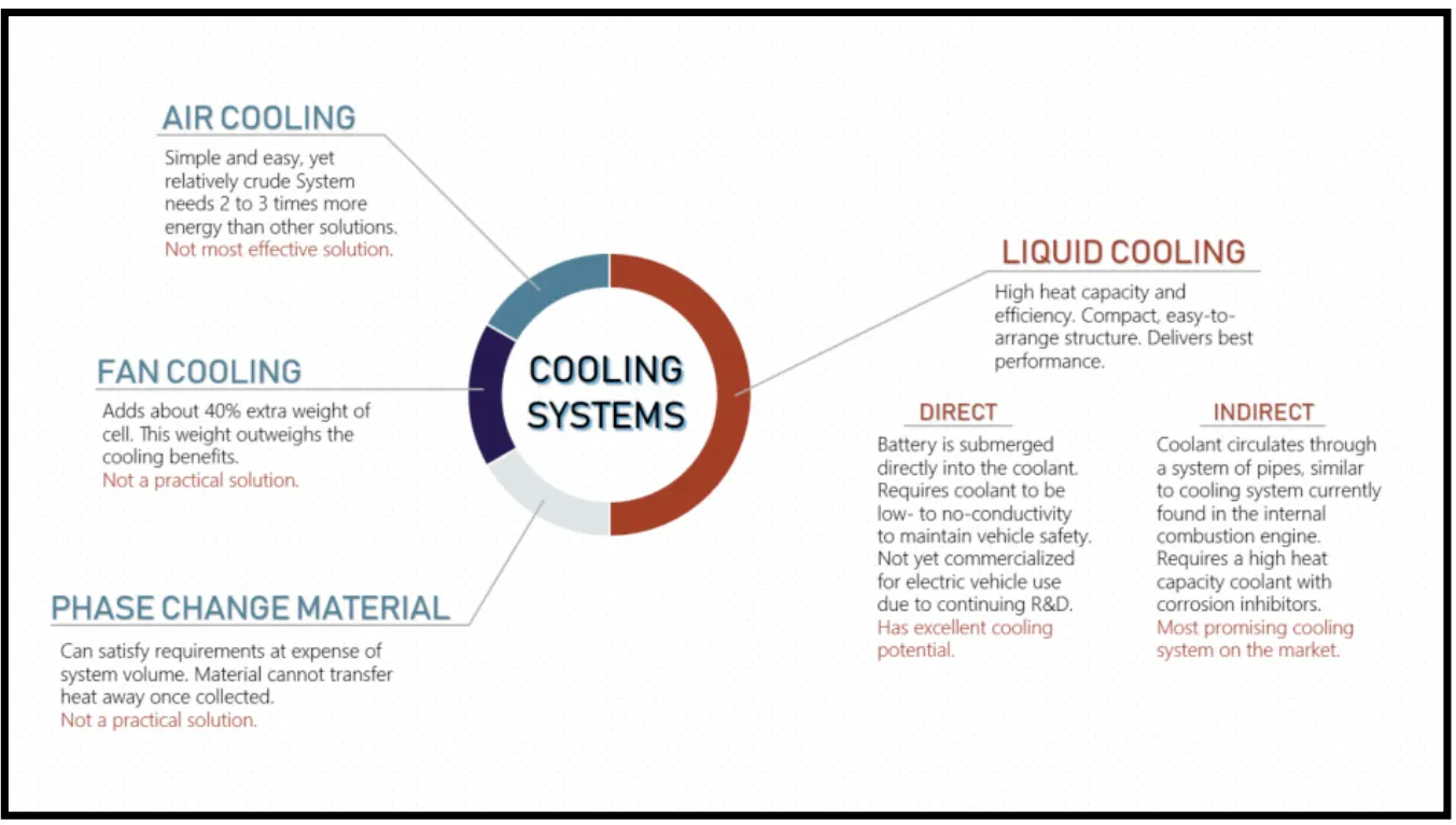
THERE ARE A FEW OPTIONS TO COOL AN ELECTRIC CAR BATTERY—WITH PHASE CHANGE MATERIAL, FINS, AIR, OR A LIQUID COOLANT.
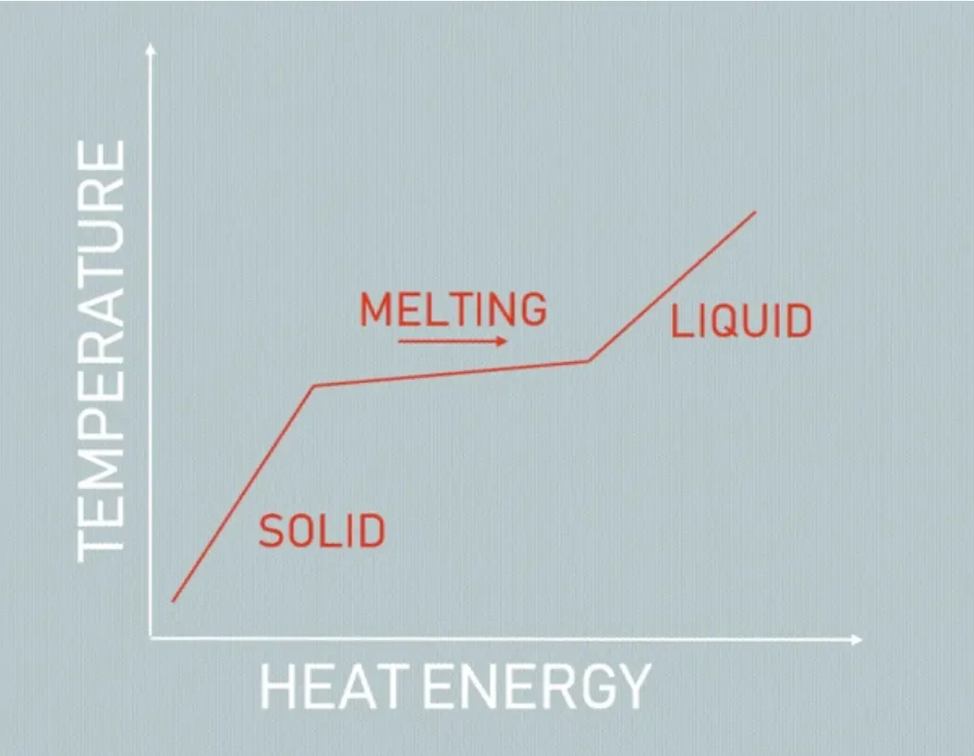
- Phase change material absorbs heat energy by changing state from solid to liquid. While changing phase, the material can absorb large amounts of heat with little change in temperature. Phase change material cooling systems can meet the cooling requirements of the battery pack, however, the volume change that occurs during a phase change restricts its application. Also, phase change material can only absorb heat generated, not transfer it away, which means that it won’t be able to reduce overall temperature as well as other systems. Although not favourable for use in vehicles, phase change materials can be useful for improving thermal performance in buildings by reducing internal temperature fluctuations and reducing peak cooling loads.
- Cooling fins increase surface area to increase the rate of heat transfer. Heat is transferred from the battery pack to the fin through conduction, and from the fin to the air through convection. Fins have high thermal conductivity and can achieve cooling goals, but they add a lot of additional weight to the pack. The use of fins has found a lot of success in electronics, and traditionally they have been used as an additional cooling system on internal combustion engine vehicles. Using fins to cool the electric car battery has fallen out of favour since the additional weight of the fins outweighs the cooling benefits.
- Air cooling uses the principle of convection to transfer heat away from the battery pack. As air runs over the surface, it will carry away the heat emitted by the pack. Air cooling is simple and easy, but not very efficient and relatively crude compared to liquid cooling. Air cooling is used in earlier versions of electric cars, such as the Nissan Leaf. As electric cars are now being used more commonly, safety issues have arisen with purely air-cooled battery packs, particularly in hot climates. Other car manufacturers, such as Tesla, insist that liquid cooling is the safest method.
- Liquid coolants have higher heat conductivity and heat capacity (ability to store heat in the form of energy in its bonds) than air, and therefore performs very effectively and own advantages like compact structure and ease of arrangement. Out of these options, liquid coolants will deliver the best performance for maintaining a battery pack in the correct temperature range and uniformity. Liquid cooling systems have their own share of safety issues related to leaking and disposal, as glycol can be dangerous for the environment if handled improperly. These systems are currently used by Tesla, Jaguar, and BMW, to name a few.
THE DETERMINING FEATURES OF AN ELECTRIC VEHICLE BATTERY COOLING SYSTEM ARE TEMPERATURE RANGE AND UNIFORMITY, ENERGY EFFICIENCY, SIZE, WEIGHT, AND EASE OF USAGE (I.E. IMPLEMENTATION, MAINTENANCE).
Each of these proposed systems can be designed to achieve the correct temperature range and uniformity. Energy efficiency is more difficult to achieve, as the cooling effects need to be greater than the heat generated when powering the cooling system. Also, a system with too much additional weight will drain energy from the car as it outputs power.
Phase change material, fan cooling, and air cooling all fail at the energy efficiency and size and weight requirements, though they may be just as easy to implement and maintain as liquid cooling. Liquid cooling is the only remaining option that does not consume too much parasitic power, delivers cooling requirements, and fits compactly and easily into the battery pack. Tesla, BMW i-3 and i-8, Chevy Volt, Ford Focus, Jaguar i-Pace, and LG Chem’s lithium-ion batteries all use some form of liquid cooling system. Since electric vehicles are still a relatively new technology, there have been problems maintaining temperature range and uniformity in extreme temperatures even when using a liquid cooling system. These are likely due to manufacturing problems, and as companies gain experience developing these systems, the thermal management issues should be resolved.
IN LIQUID COOLING SYSTEMS, THERE IS ANOTHER DIVISION BETWEEN DIRECT AND INDIRECT COOLING—WHETHER THE CELLS ARE SUBMERGED IN THE LIQUID OR IF THE LIQUID IS PUMPED THROUGH PIPES.
- Direct cooling systems place the battery cells in direct contact with the coolant liquid. These thermal management schemes are currently in the research and development stage, with no cars on the market using this system. Direct cooling is more difficult to achieve, due to the fact that a new type of coolant is required. Because the battery is in contact with the liquid, the coolant needs to have low to no conductivity.
- Indirect cooling systems are similar to ICE cooling systems in that both circulate liquid coolant through a series of metal pipes. However, the construction of the cooling system will look much different in electric vehicles. The structure of the cooling system that achieves maximum temperature uniformity is dependent on the shape of the battery pack and will look different for each car manufacturer.
REQUIREMENTS FOR LIQUID COOLANTS
Making coolants safe and effective
Given that liquid cooling is the most efficient and practical method of cooling battery packs, and currently the most widely used, attention needs to be given to the type of coolant used in these systems.
INDIRECT LIQUID COOLING
The indirect liquid cooling systems for electric vehicles and the conventional internal combustion engine (ICE) cooling system are very similar: both circulate coolant throughout a series of metal pipes to transfer heat away from the battery pack or engine. Therefore, coolant requirements for indirect liquid cooling systems will be very similar to traditional ICE coolants.
99% of the coolant is a commodity such as glycol or polyglycol, but the 1�ditive package is what separates good from great engine protection and performance. When circulating a liquid coolant throughout metal piping, it is important to protect against corrosion to protect vehicle safety and performance.
</> < >>Additive packages can be blended with antifreeze to form a coolant that protects against rust, scale, and corrosion. The additive packages used in ICE vehicles contain corrosion inhibitors to protect the many types of metals found in cooling systems, such as pipes, gaskets, connections, radiator, etc. The American Society for Testing and Materials maintains standards that coolants must meet for protection against the corrosion of different metal types. What is currently known about corrosion prevention in internal combustion engine cooling systems can be easily applied to the indirect liquid cooling system in electric vehicles.
DIRECT LIQUID COOLING
There are different coolant requirements for direct liquid cooling systems. In systems where the battery will be directly exposed to the coolant, such as with Fuel Cell Vehicles or direct liquid cooling, the coolant needs to be a low to no conductivity fluid. This is going to be very different from conventional ICE coolants that have a high conductivity. The reason for needing low/no conductivity is due to safety: electrons are flowing throughout the battery, and if they are exposed to a high conductivity fluid, this will lead to failure and explosion. Some examples of ways to keep coolant conductivity low are using deionised water as a medium for the fluid or having a non-salt-based fluid medium. These low- and no-conductivity coolants are in the early stages of research and development.
A battery thermal management system controls the temperature of the batteries so that they work safely and well. High temperatures can make batteries age faster and pose safety risks, while low temperatures can reduce the battery's capacity and make it less efficient at charging & discharging.
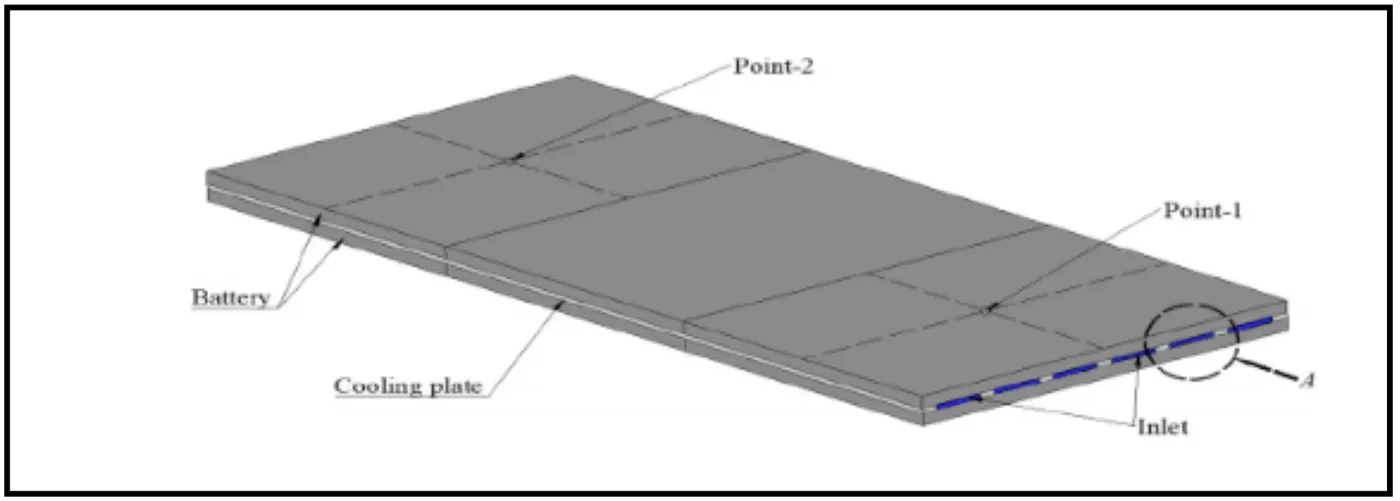
A thermal management system for a battery controls how hot or cold the battery can get by either letting heat out when it gets too hot or putting heat in when it gets too cold. Engineers can change the temperature of the battery in these systems by using active, passive, or hybrid methods of heat transfer. Most active solutions use a fan or pump to move a working fluid, like air, water, or another liquid, to lower or raise the temperature of the battery. In a passive solution, heat is moved away from the battery by heat sinks or pipes made of materials that conduct heat well. A hybrid solution takes the best parts of both active & passive solutions and puts them together.
Engineers can analyse tradeoffs in design parameters, evaluate performance & implement control algorithms with the help of thermal software models that simulate how heat moves through a battery. Engineers can use MATLAB and Simulink to design thermal management systems for batteries. These systems make sure that a battery pack works well & safely in a wide range of operating conditions.
Model the battery's temperature in great detail.
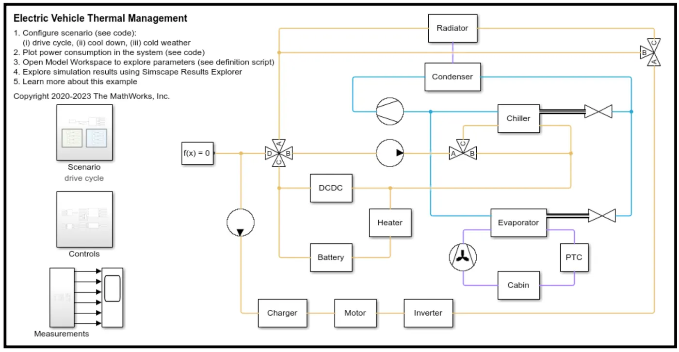
Make models for cooling & heating systems that use fluids that change phase, such as gases, liquids & refrigerants.
Modelling and simulation can be used to choose and size components.
Explore the design space with different parameters for each component and improve the performance of the battery thermal management system.
To plan for "what-if" situations, you can simulate extreme temperatures.
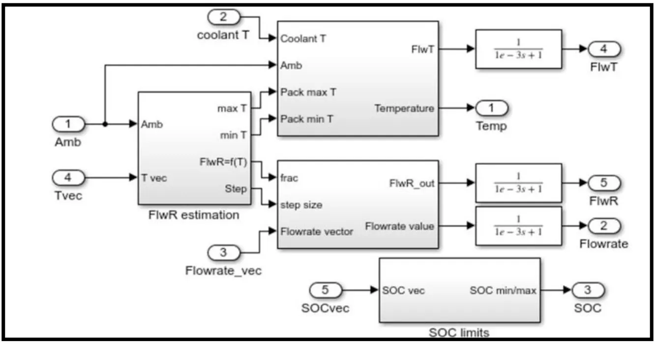
Design closed-loop control strategies and supervisory control logic for temperature modulation.
Do scenario studies to figure out how different design choices will affect the temperature.Reduce costs by testing production battery hardware less often & for less money.Automatically create embedded code for battery thermal management controls that is ready for production & check it against industry standards.
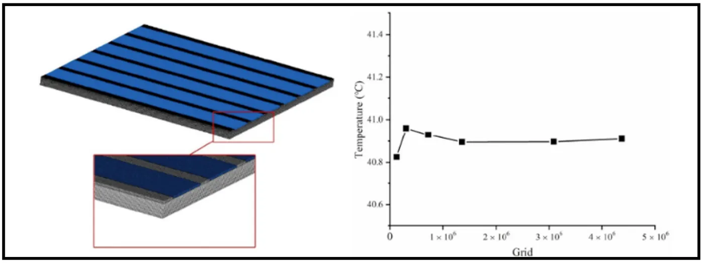
When lithium-ion batteries are being charged or drained, heat is made, which changes the temperature distribution in the battery modules and packs in a big way. In this work, experimental data are used to make a model of how heat is made by a lithium-ion battery. Fora BTMS, the heat transfer model is combined with the liquid cooling method to make it even better. For the cooling plate structure parameters and cooling strategies, the orthogonal design method is used to do the matrix analysis. The BTMS control strategies are evaluated based on how well they work, how safe they are in terms of heat, and how much electricity they need.
The following are the main conclusions:
1) The thermal contact resistance between the battery and the cooling plate surfaces where they touch directly is large and needs to be taken into account when modelling the temperature distribution.
2) When it comes to the temperature distribution in the battery module, the inlet flow rate is the most important factor for the rectangular channels in the cooling plates. Also, increasing the channel height can effectively reduce the BTMS's parasitic energy use.
3) In which changes the flow rate at the module's inlet, is thought to be the best temperature control scheme for the BTMS in this work because it keeps the temperature range in the module within a reasonable range and uses less energy. Also, for Strategy (a), the response time of BTMS is only affected by the way the temperature is spread, not by how long it takes the batter to discharge or charge.
>>
< ><>>:</>
< class>SA_Bbox = 0.2 m2
BboxThickness = 1 mm=0.001m
K_Bbox = 60 W/mk
Bbox air volume = 0.05 m3
Resin:
Resin Thickness = 3 mm=0.003m
K_Resin = 1.8 W/mk
Thermal interface material:
TIM Thickness = 1 mm=0.001m
K_TIM = 3W/mk
Foam:
Foam Thickness = 10 mm=0.01m
K_Foam = 0.05 W/mk
Module Mass = 13.5 kg
Cp_Cell = 1015 J/kgk
k_Cell = 25 W/mk
Module Thickness = 108 mm=0.108m
Module Length = 390 mm=0.39m
Module Width = 152 mm=0.152m
Heat generation = 2 W
For pipes, use these dimensions:
Pipe length = 50 mm=0.05m
CS area = 123 mm2=0.000123m^2
Hydraulic diameter = 12.5 mm =0.0125m
EV Battery Cooling System
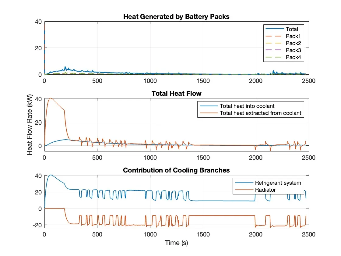
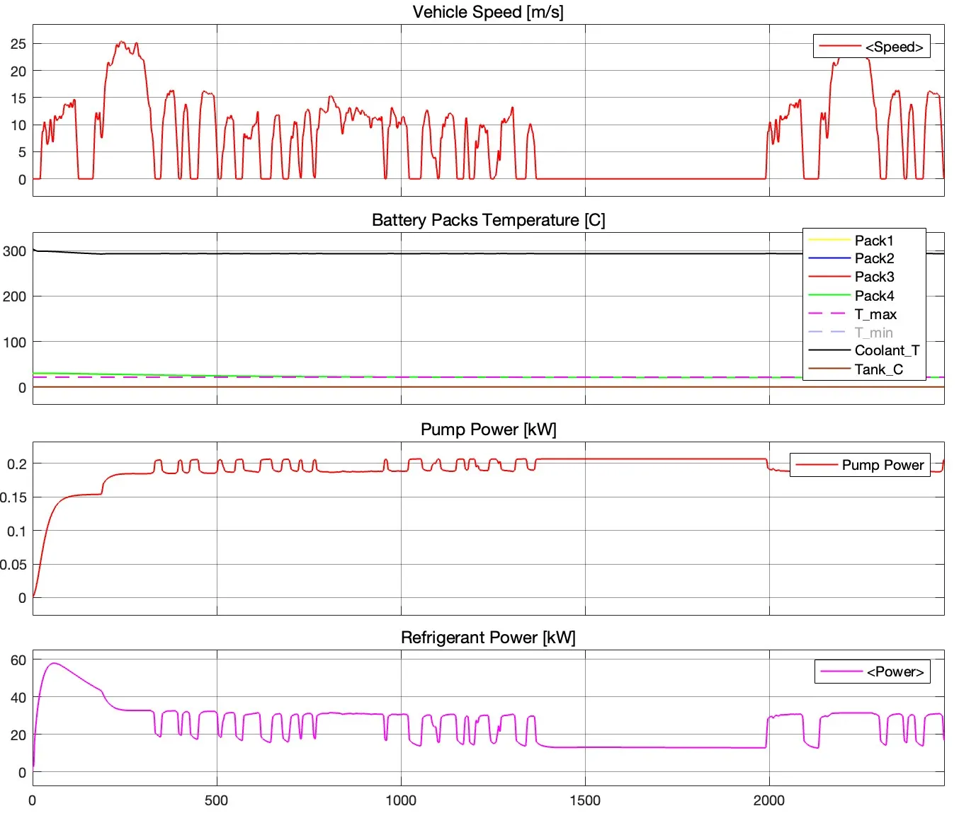
This demo shows an Electric Vehicle (EV) battery cooling system. The battery packs are located on top of a cold plate which consists of cooling channels to direct the cooling liquid flow below the battery packs. The heat absorbed by the cooling liquid is transported to the Heating-Cooling Unit. The Heating-Cooling Unit consists of three branches to switch operating modes to cool and heat the battery. The Heater represents an electrical heater for fast heating of the batteries under low temperature conditions. The Radiator uses air-cooling and/or heating when the batteries are operated stably. The Refrigerant system is used for cooling the overheated batteries. The refrigeration cycle is represented by the amount of heat flow extracted from the cooling liquid. The system is simulated under either FTP-75 drive cycle or fast charge scenarios with different environment temperatures.
Model
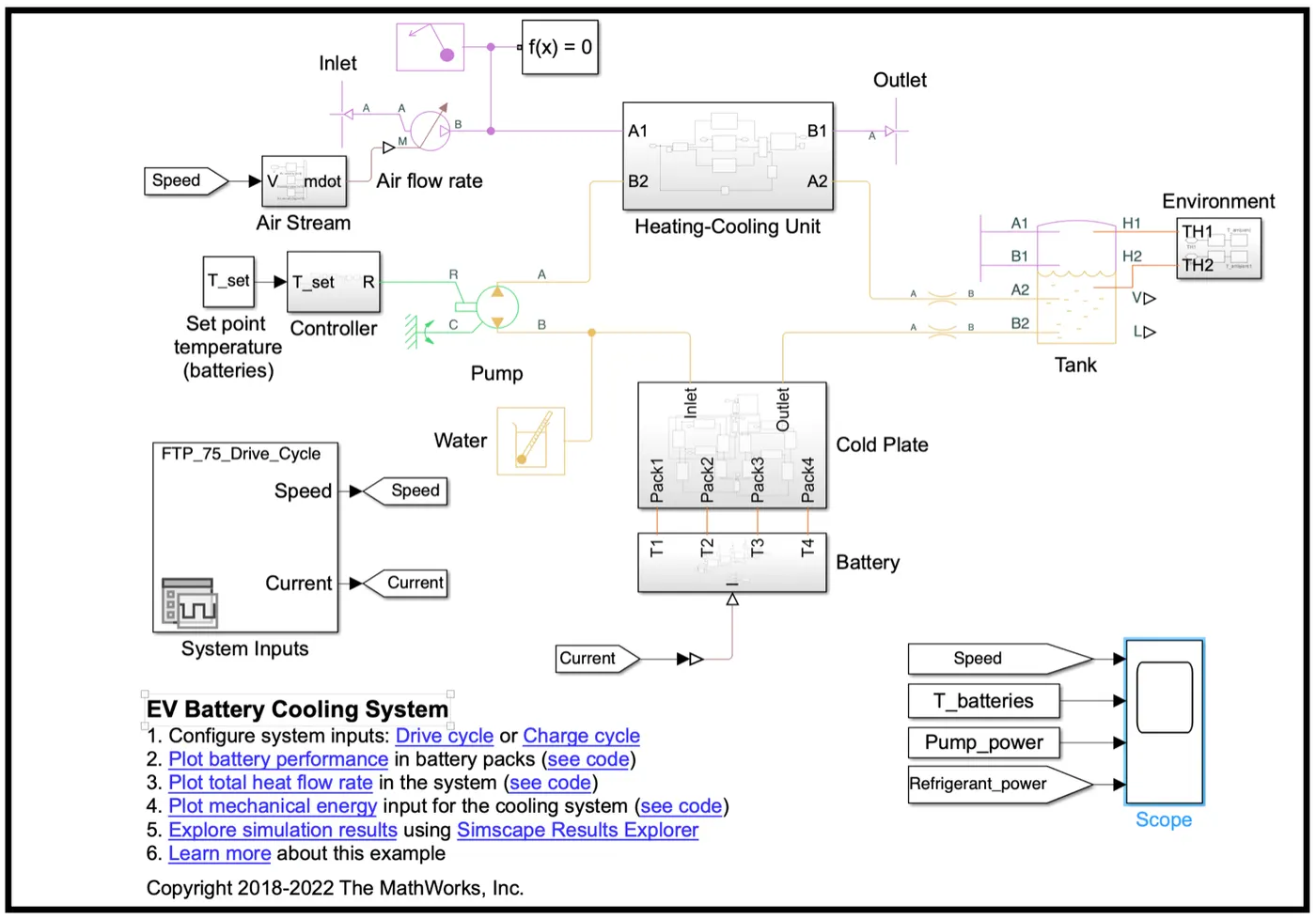
Battery Subsystem
Cold Plate Subsystem
Cooling Plate (Pack 1) Subsystem
Heating-Cooling Unit Subsystem
Refrigerant Subsystem
Radiator Subsystem
Heater Subsystem
Pump Controller
Air Stream
Environment
Simulation Results from Scopes