Project 1 - 1d modelling of liquid cooling system
Problem Description:
we have a cooling plate mounted with 2 modules, each containing multiple cells. The flow pattern indicates that water is used as the coolant, flowing from a tank of limited capacity. The goal is to analyze the thermal behavior of the system, including plotting the top and bottom module temperatures, and studying the effects of tank capacity and coolant flow rate on battery and coolant temperatures.
Approach:
-
Define the System:
- Identify the components involved: cooling plate, 2 modules, cells, water coolant, and a tank.
- Understand the geometry and arrangement of these components.
- Define the system boundaries, control volumes, and assumptions.
-
Set Up Physical Equations:
- Utilize principles of heat transfer and fluid dynamics to establish the equations governing temperature distribution and fluid flow.
- Consider conduction within the modules, convection between modules and coolant, and heat generation by cells.
-
Numerical Modeling:
- Develop a numerical model to solve the partial differential equations (PDEs) representing heat transfer and fluid flow.
- Use finite difference, finite element, or other appropriate numerical methods.
-
Implement in MATLAB/Simulink:
- Create a Simulink model representing the cooling plate system.
- Define blocks for modules, cells, coolant, tank, and other components.
- Configure parameters such as module dimensions, coolant properties, flow rates, tank capacity, etc.
-
Boundary Conditions:
- Specify initial conditions (temperatures, pressures) for modules, coolant, and tank.
- Set boundary conditions for cells, modules, and coolant.
-
Solver Settings:
- Choose appropriate solver settings in Simulink for solving the transient heat transfer and fluid flow equations.
- Consider fixed-step or variable-step solvers, time steps, convergence criteria, etc.
-
Run Simulations:
- Run the Simulink model for different scenarios.
- Vary tank capacity and coolant flow rate to observe their effects on battery and coolant temperatures.
-
Data Collection and Analysis:
- During simulation runs, collect data such as module temperatures, coolant temperatures, and other relevant variables.
-
Plotting Results:
- Use MATLAB's plotting functions to create graphs showing top and bottom module temperatures as functions of time or other variables.
-
Interpretation:
- Analyze the plotted results to draw conclusions about the system behavior.
- Evaluate how changing tank capacity and coolant flow rate impact battery and coolant temperatures.
-
Sensitivity Analysis:
- Perform sensitivity analysis to understand the relative importance of different parameters.
- Identify critical parameters that strongly influence the system behavior.
-
Report and Recommendations:
- Compile your findings, including plots, graphs, and insights gained from simulations.
- Summarize how tank capacity and coolant flow rate affect battery and coolant temperatures.
- Provide recommendations for optimal tank capacity and coolant flow rate based on your analysis.
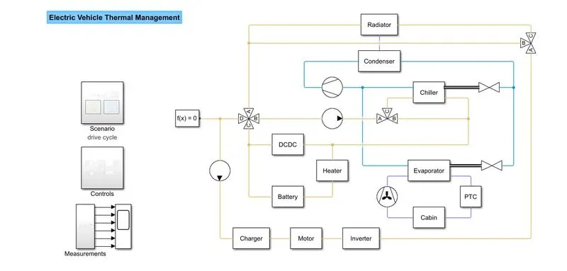
1D Cooling System:
A battery thermal management system controls the temperature of the batteries so that they work safely and well. High temperatures can make batteries age faster and pose safety risks, while low temperatures can reduce the battery's capacity and make it less efficient at charging and discharging.
A thermal management system for a battery controls how hot or cold the battery can get by either letting heat out when it gets too hot or putting heat in when it gets too cold. Engineers can change the temperature of the battery in these systems by using active, passive, or hybrid methods of heat transfer. Most active solutions use a fan or pump to move a working fluid, like air, water, or another liquid, to lower or raise the temperature of the battery. In a passive solution, heat is moved away from the battery by heat sinks or pipes made of materials that conduct heat well. A hybrid solution takes the best parts of both active and passive solutions and puts them together.
Engineers can analyse tradeoffs in design parameters, evaluate performance, and implement control algorithms with the help of thermal software models that simulate how heat moves through a battery. Engineers can use MATLAB and Simulink to design thermal management systems for batteries. These systems make sure that a battery pack works well and safely in a wide range of operating conditions.
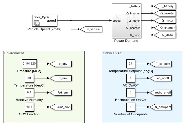
Scenario Subsystem
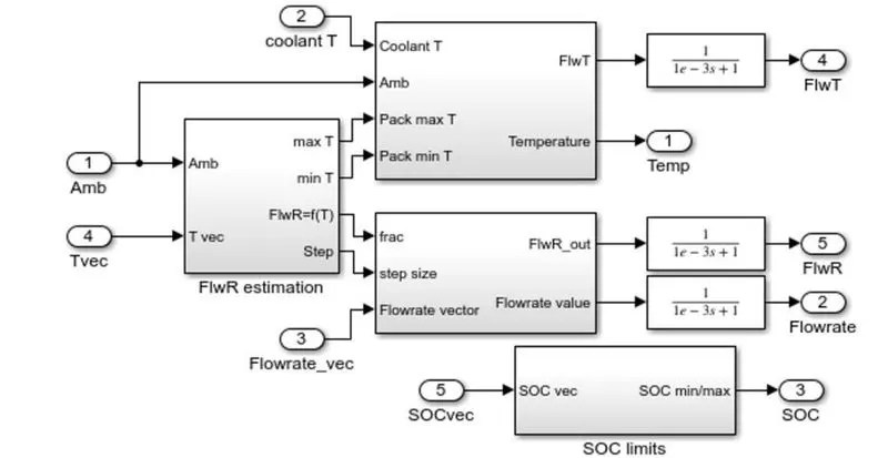
This subsystem sets up the environment conditions and inputs to the system for the selected scenario. The battery current demand and powertrain heat load are a function of the vehicle speed based on tabulated data.
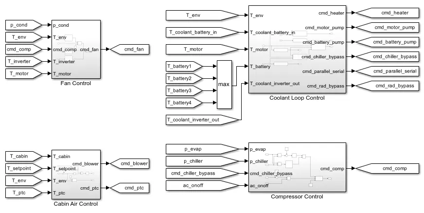
Controls Subsystem
This subsystem consists of all of the controllers for the pumps, compressor, fan, blower, and valves in the thermal management system.
�ttery box enclosure properties
SA_Bbox = 0.2; % m^2
BboxThickness = 0.001; % m (1 mm)
K_Bbox = 60; % W/mK
Bbox_air_volume = 0.05; % m^3
% Resin properties
ResinThickness = 0.003; % m (3 mm)
K_Resin = 1.8; % W/mK
% Thermal interface material properties
TIM_Thickness = 0.001; % m (1 mm)
K_TIM = 3; % W/mK
% Foam properties
FoamThickness = 0.01; % m (10 mm)
K_Foam = 0.05; % W/mK
% Module properties
ModuleMass = 13.5; % kg
Cp_Cell = 1015; % J/kgK
k_Cell = 25; % W/mK
ModuleThickness = 0.108;% m (108 mm)
ModuleLength = 0.39; % m (390 mm)
ModuleWidth = 0.152; % m (152 mm)
HeatGeneration = 2; % W
% Pipe properties
PipeLength = 0.05; % m (50 mm)
CS_Area = 0.000123; % m^2 (123 mm^2)
HydraulicDiameter = 0.0125; % m (12.5 mm)
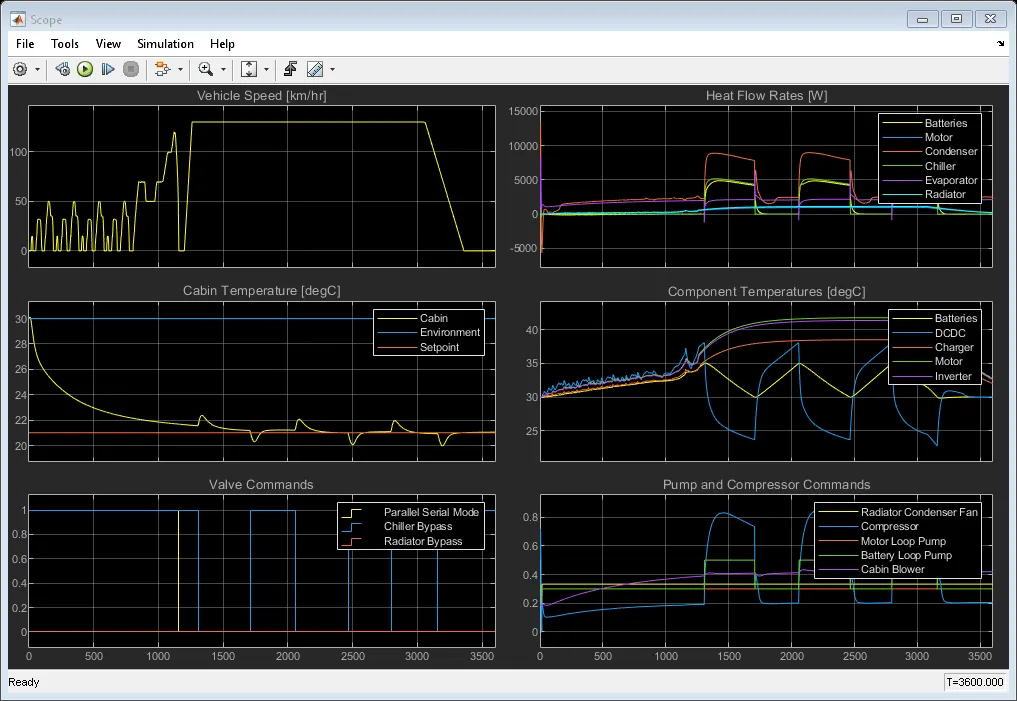
Result: