Project 1
Q-Given below is a plan view of a framing layout of a typical school classroom. Design beam marked B1 and the floor slab per IS 456-2000. Use M25 concrete and Fe 415 steel. Use 20 mm clear cover for slab and 30 mm clear cover for beam. Consider a 2.5 kN/m2 super imposed dead load accounting for floor finish and ceiling.
AIMS AND INTRODUCTION :
Beam marked B1 and the floor slab of given framing layout of a typical school classroom is to be designed per IS 456-2000.
Given Inputs :
Concrete : M25 so `f_(ck) = 25 N//mm^2`
Steel : Fe415 so `f_y = 415 N//mm^2`
Clear cover for slab : 20 mm
Clear cover for beam : 30 mm
Superimposed dead load ( FF &Ceiling ) : 2.5 kN/`m^2`
PROCEDURE IN DETAIL :
Design of slab :
step-1 : Type of slab :
`l_y/l_x` = 8/3 = 2.66 > 2 so it is one way slab
STEP-2 : Trial depth & Effective depth-
Total depth of slab (d) = l/25 = 3000/30 = 100 mm ( Thumb rule)
Assuming dia of bar = 10 mm
Clear cover = 20 mm
Effective depth of slab (d) = D -Clear cover -`phi/2`
100 = D - 20 - 10/2
D = 125 mm
Effective span : [ Lesser of ( i) clear span =d and clear span + width of support ]
Assuming Column of size 300 mm x 300 mm and width of beam 250 x 450 mm which support the slab
So, clear span of slab = 3000 +250 = 2750 mm = 2.75 m
Width of support i.e. width of beam = 250 mm
(1/12) of clear span = (1/12) * 2750 = 229 mm
If width of support is less than (1/12)th of clear span then effective span of continous slab will be as per cl. 22.2 (a) of IS 456 :200
( i) `l_(eff)` = clear span +d
= 2750 +100 + = 2850mm
( ii) `l_(eff)` = center to center distance = 2750 mm
Lesser of (i) & (ii)
`therefore` Effective Span `l_(eff)` = 2.750 5m
Step -3 : Design load & Factored moment :
Dead load of slab OR Self weight of slab = D*b* unit weight of RCC
= 0.125 m *25 `kN//m^3`
= 3.125 kN/`m^2`
Load per meter width = 3.125*1 = 3.125 kN/m
Factored Dead load = 1.5*3.125 = 4.69 kN/m
Superimposed dead load = 2.5 kN/`m^2`
Superimposed/Live load per meter width = 2.5*1.0 = 2.5 kN/m
Factored Live/Super imposed load = 1.5(LL)
= 1.5 ( 2.5)
= 3.75 kN/`m
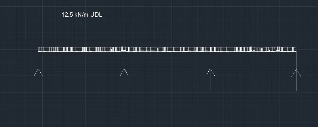
Table 12: Bending moment coefficient for continous slab as per clause 22.5 of IS 456 : 200
| Span moment | Support moment | |||
| Near middle of end span | At middle of the interior span | At support next to the end support | At other interior support | |
| Dead load | +1/12 | +1/16 | -1/10 | -1/12 |
| Imposed load | +1/10 | +1/12 | -1/9 | -1/9 |
Moment at middle of the end span `( M_P & M_S)` = 1/12*`w_u(DL)*l_(eff)^2 + 1/10*w_u(LL)*l_(eff)^2`
= 1/12*4.69*`2.75^2`+ 1/10*3.75*`2.75^2`
= 2.96+2.84 = 5.8 kNm
= 5.8 kNm
Moment At middle of the interior span ( `(M_Q or M_R )` = 1/16*`w_u(DL)*l_(eff)^2 + 1/12*w_u(LL)*l_(eff)^2`
= 1/16 *4.69*`2.75^2`+ 1/12*3.75*`2.75^2`
= 2.22 + 2.36 = 4.58 kNm
Moment At support next to the end support `(M_B & M_D)` = -1/10*`w_u(DL)*l_(eff)^2 - 1/9*w_u(LL)*l_(eff)^2`
= - ( 1/10* 4.69*`2.75^2`+ 1/9*3.75*`2.75^2`)
= - ( 3.55 +3.15) = 6.7 kNm
= -6.7 kNm
Moment At other interior support ( `M_C`) = -(1/12*`w_u(DL)*l_(eff)^2 + 1/9*w_u(LL)*l_(eff)^2`)
= -( 1/12*4.69*`2.75^2`+ 1/9*3.75*`2.75^2`)
= -( 2.96 + 3.15 ) = 6.11 kNm
= - 6.11 kNm
Thus Max. +ve moment at mid span = 5.8 kNm
Max -ve moment at support = 6.7 kNm
`M_u(lim)=0.138f_(ck)bd^2`
= 0.138 *25*1000*100*100
= 34.5 kNm
So section is under tension as `M_u (lim) gt M_u`
Step-4 : Check for Thickness of slab:
`M_u = 0.138*f_(ck)*b*d^2`
`6.7*10^6`= 0.138*25*1000*`d^2`
`d^2`= 1942
d= 44 mm which is less than d adopted ( 100 mm ) , hence safe
Step-5 :Calculation of Steel reinforcement:
i) At center of end span
`A_(st1)= (0.5f_(ck))/(f_y )[ 1-sqrt[1-4.6M_u /(f_(ck)bd^2]]]bd`
= 0.5*25/415 [ 1-( 1-4.6*5.8*`10^6`/25*1000*`100 ``^2`)`^0.5`]*1000*100
= 0.03 [1- (1-0.10672]`^0.5`*`10^5`
= 0.03 (1- (0.89)`^0.5`*`10^5`
= 0.03*( 1-0.944)*100000
= 0.03*0.0566*`10^5`
= 169.81 `mm^2`
Provide `A_(st1)` = 200 `mm^2`
Using 10 mm`phi` bar
Area of each bar `a_phi = (pi/4)*phi^2`
= 22/7* 1/4* 10^2
= 78.57 `mm^2`
C/C Spacing of bar (s) = `1000*a_(phi)/A_(st)`
= 1000* 78.57/200 = 392 .85 mm c/c
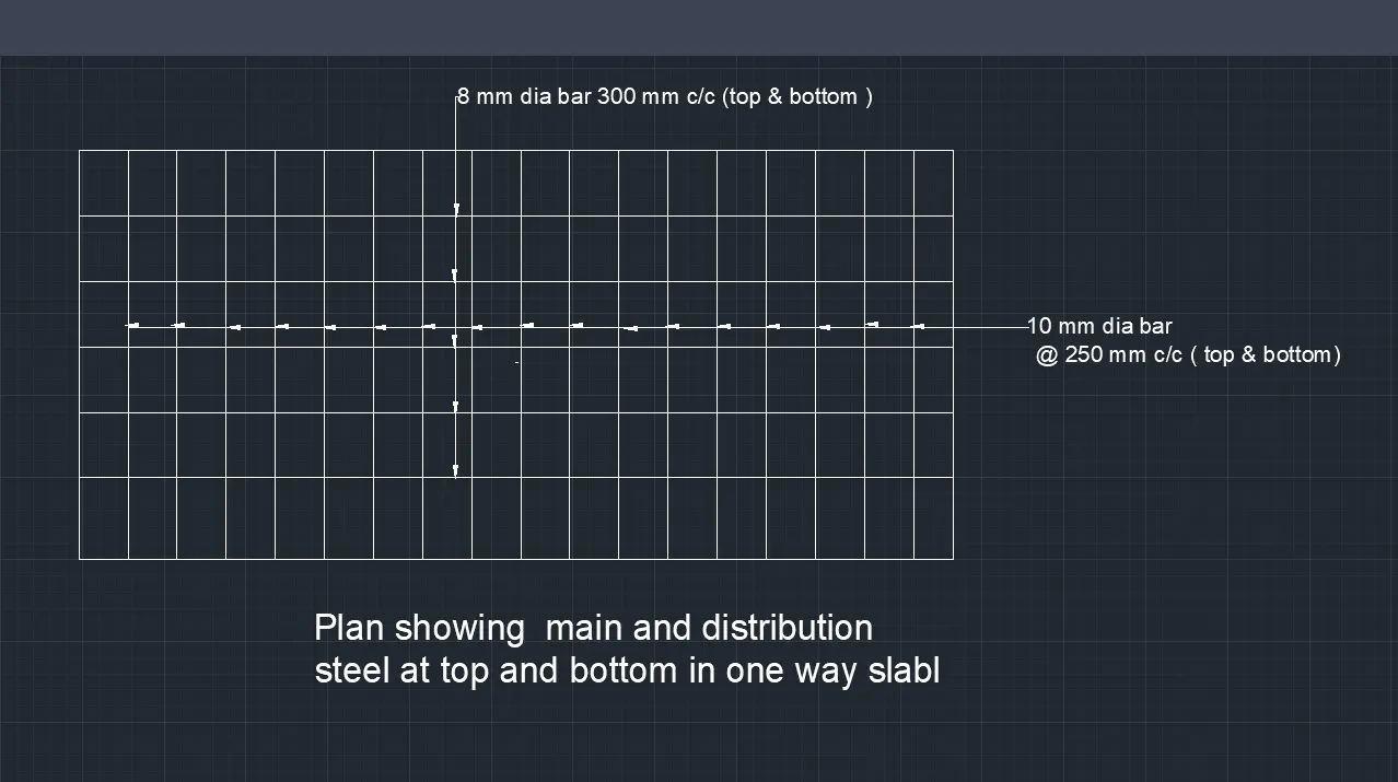
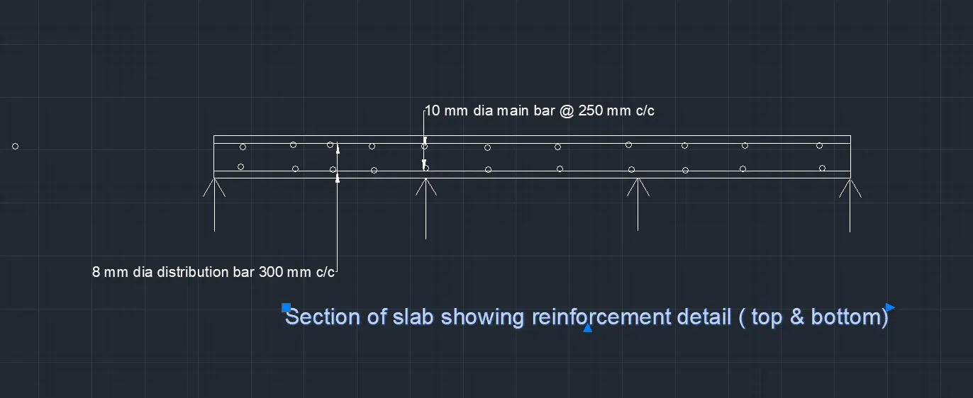
Providing 10 mm `phi` bar @ 250 mm c/c, ( Tension zone)
Check for spacing for minimum steel : ( As per cl . 36.3.3 (b) , IS 456 :2000
i) 3d = 3* 100 = 300 mm
(ii) 300 mm
Lesser of (i) & (ii)
Provided spacing is 250 mm c/c < required spacing ( OK)
so `A_(st)` provided = `1000*a_(phi)/s`= 1000*78.57/250 = 314 `mm^2`
= 314 `mm^2` > `A_(st)`required ( 169.81 `mm^2` ( Safe)
Percentage of steel provided = `A_(st)`/bd
= (314/1000*100) *100 = 0.314 % > 0.12 % ( min as per codal provision)
Reinforcement for _ve moment at support :
At support next to end support :
`A_(st2)= (0.5f_(ck))/(f_y )[ 1-sqrt[1-4.6M_u /(f_(ck)bd^2]]]bd`
= 0.5*25/415 [ 1-( 1-4.6*6.7*`10^6`/25*1000*`100 ``^2`)`^0.5`]*1000*100
= 0.03 [1- (1-0.123]`^0.5`*`10^5`
= 0.03 (1- (0.878)`^0.5`*`10^5`
= 0.03*( 1-0.935)*100000
= 0.03*0.065*`10^5`
= 195 `mm^2`
Provide `A_(st2)` = 200 `mm^2`
Using 10 mm`phi` bar
Area of each bar `a_phi = (pi/4)*phi^2`
= 22/7* 1/4* 10^2
= 78.57 `mm^2`
C/C Spacing of bar (s) = `1000*a_(phi)/A_(st)`
= 1000* 78.57/200 = 392 .85 mm c/c
Providing 10 mm `phi` bar @ 250 mm c/c, ( Compression zone)
Check for spacing for minimum steel : ( As per cl . 36.3.3 (b) , IS 456 :2000
i) 3d = 3* 100 = 300 mm
(ii) 300 mm
Lesser of (i) & (ii)
Provided spacing is 250 mm c/c < required spacing ( OK)
so `A_(st)` provided = `1000*a_(phi)/s`= 1000*78.57/250 = 314 `mm^2`
= 314 `mm^2` > `A_(st)`required ( 169.81 `mm^2` ( Safe)
Percentage of steel provided = `A_(st)`/bd
= (314/1000*100) *100 = 0.314 % > 0.12 % ( min as per codal provision)
Distribution steel in longer direc tion : ( As per cl.26.5.2.1 IS 456 : 2000 , Page-48)
0.12% of X-sectional area = 0.12/1000* 100*100 = 120 `mm^2`
Using 8 mm `phi` bar
Area of one bar , `a_(st)` = `pi/4xxphi^2`
= (3.14/4)x 8x8
= 50.24 `mm^2`
Spacing of bar ( s ) = 1000x`a_(st)/A_(st)`
= 1000 (50.24/120) = 418 sqmm
Providing Distribution bar 8 mm `phi` 300 mm c/c
As per cl 26.3.3 (b) (2) of IS 456 :2000
Spacing should not be more than smaller of (i) 5d = 5*95 =475 mm
( ii) 450 mm
Thus 300 mm < 450 mm ( OK)
Analysis and design of beam B-1
`w_(DL) (slab) =` 3.125 kN/`m^2` ( thickness of slab = 125 mm so its dead load = 25 *0.125)
Dead load of one way slab comming on to the beam as UDL = (1.5+1.5)* 3.125 = 9.375 kN/m
`w_(LL)(slab)` = 2.5 kN/`m^2`
`
Cross-sectional dimension of beam :`d_(eff) = (1/15)^(th) to (1/20)^(th)`of span
= 1/15* 8000 = 533.34 mm & 1/20*8000 = 400 mm
Assume `d_(eff)`= 465 mm
Assuming nominal cover = 1/2 *dia of bar + clear cover = 20 + 30/2 =35 mm
Over all depth of beam, D = 450 + 35 = 500 mm
Assume, b = 250 mm
Design m,oment (`M_u`) :
Self weight of beam , `w_(DL)(Beam)` = 0.25*0.5*25 kN/`m^3` = 3.125 kN/m
Factored UDL on beam due to DL of slab & beam = 3.125 kN/m + 9.375 = 18.75 kN/m
UDL on beam due to Live load = 2.5 *3 = 7.5 kN/m
Factored LL load on beam = 1.5 *7.5 = 11.25 kN/m
Calculation of span moment :
Moment at end span = (1/12)*`w_u(DL)* l^2` + (1/10) `w_u(LL)*l^2`
= (1/12)*18.187*8^2 + (1/10)* 11.25* `8^2` = 169 kNm
Moment at middle of interior support = (1/16)*`w_u(DL)*l^2`+ (1/12)*`w_u(DL)*l^2`
= (1/16)* 18.187* 64 + (1/12) * 11.25*64
= 72.8 + 60 = 132.8 kN-m
Calculation of support moments :
Moment at suppor next to end support = (1/10)w_u(DL)*l^2 + (1/9) w_u(LL)* l^2
= (1/10)* 18.187*64 +(1/9)* 11.25*64
= 116.4 +80 = 194.4 kNm
Moment at other interior suppots = (1/12)*`w_u(DL)*l^2`+ (1/9) * `w_u(LL)*l^2`
= (1/12)*18.187*64 + (1/9)*11.25*64
= 97.0 +80 = 177 kNm
Maximum +ve moment = 169 kNm
Maximum -ve moment = 194.4 kNm
Design of longitudinal reinforcement :
`M_u (lim)= 0.36*x_u(max)//d`(1-0.42 `x_u(max)//d`)`bd^2f_(ck)`
= 0.36*0.48 (1-0.42*0.48)*300*465*465*25
= 0.1728*0.7984* 1621687500
= 223 x`10^6`N-mm
= 223 kNm
`M_u(lim)` ( 223 kNm) > `M_u`( 194.4 kNm) so beam will be singly reinforced ( Under reinforced section)
Tension reinforcement :
`A_(st)= (0.5f_(ck)/f_y)[1-{1-(4.6 M_u)/(f_(ck)bd^2)}^0.5 ]bd`
= (0.5*25/415)[1-{ 1- (4.6* 169*`10^6`)/25*300*`465^2`)}`^0.5`] 300*465
= 0.03 [1-{1-(0.48)}`^0.5`]*139500
= 0.03 [1-{0.52}`^0.5`]* 139500
= 0.03 ( 1-0.72)* 139500
`A_(st)` = 1171 `mm^2`
Using 20 mm `phi` bars
`a_(st) =pi/4*phi^2`
= (3.14/4)*20*20 = 314 `mm^2`
Number of bars = `A_(st)/a_(st)` = 1171/314 = 3.7 say 4 Nos of bar
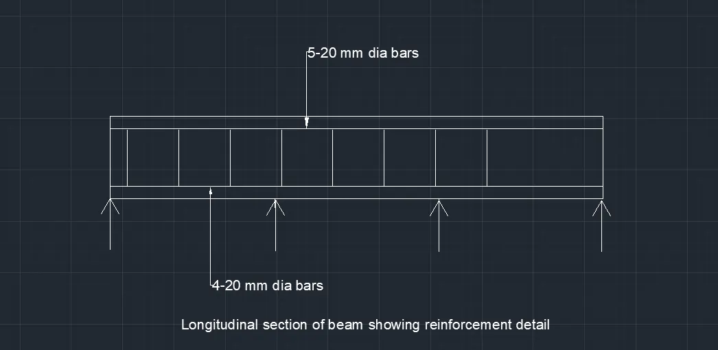
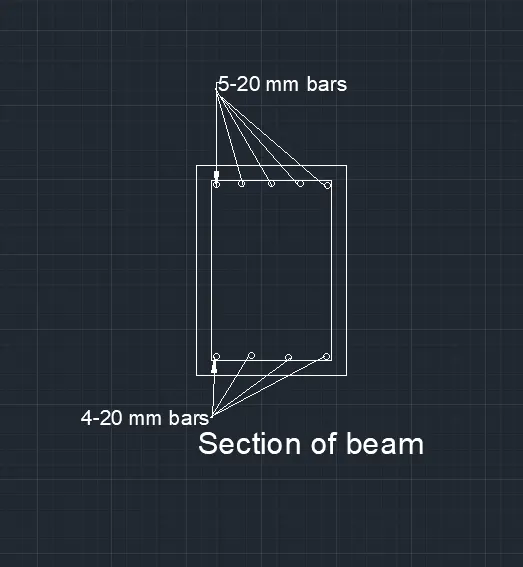
Provide 4-20 mm `phi`bars @ Tension side
Actual `A_(st)`provided = 4*314 = 1256 `mm^2`
As per clause 26.5 of S 456 :2000 Minimum reinforcement = `0.85bd//f_y` = 0.85*300*465/415 = 285 mm^2
Max `A_(st)` = 0.04b*D = 0.04*300*500 = 6000`mm^2`
Thus `A_(st)min`( 285) < `A_(st)provided`(1256)< `A_(st)max`( 6000)
Steel at supports :
`A_(st) support= (0.5f_(ck)/f_y)[1-{1-(4.6 M_u)/(f_(ck)bd^2)}^0.5 ]bd`
= (0.5*25/415)[1-{ 1- (4.6* 194*`10^6`)/25*300*`465^2`)}`^0.5`] 300*465
= 0.03 [1-{1-(0.55)}`^0.5`]*139500
= 0.03 [1-{0.45}`^0.5`]* 139500
= 0.03 ( 1-0.67)* 139500
`A_(st)` support = 1378`mm^2`
Providinf 5-20 mm `phi` bar at supports
RESULT : Slab and continous beam is designed as above, the design parameters are as follows-
Slab : i) Over all thickness D = 125 mm
ii) Effective depth d = 100 mm
iii) Span reinforcement 10 mm dia bar @ 250 mm c/c top & bottom
iv) Distribution steel 8 mm dia bar @ 300 mm c/c top & bottom
Beam ( B1) : i) Over all depth D =500 MM
ii) Effective depth d = 465 mm
iii) Tension rebar 4-20 mm dia bars
iv) Support rebars 5- 20 mm dia bars
------------------xxxxxxxxxxxxx-------------------------------xxxxxxxxxxxxxxxxxxxxx--------------------