Week 4 Challenge
Q-1. Section classification problem for listed beam shapes
Calculate section classification of following beam shapes
- ISMB 500
- ISMC 200
- PG 1300 x 450 x 50 x 12
- Double angle (Back to back) – 2 x ISA 75x75x6
- RHS - 150 x 100 x10
- Builtup box – 1000 x 450 x 20 x 12
Aim & Introduction- Structural steel sections are to be clssified into Plastic ( Class-1) , Compact ( Class-2) , Semi compact ( Class-3) & Slender ( Class-4)
Given section- ISMB 500 -
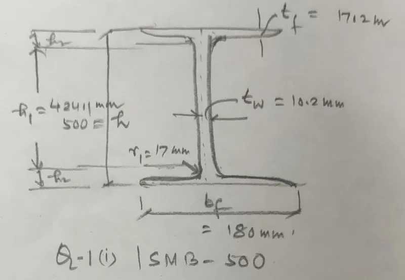
Properties of given section from steel table- `b_f`=180 mm , `t_f`= 17.2 mm , `t_w`= 10.2 mm , `r_1`=17 mm , `h_1`=424.1 mm
Procedure ( Solution)-
As per table-2 at page no-18 0f IS 800 : 2007
b= `(b_f//2)`= 180/2= 90 mm
b/`t_f`= 90/17.2 = 5.23 <9.4`epsilon` where `sqrt(250/f_y)` =1
Flange is class-1 or Plastic section
d/`t_w`= 424.1/10.2 = 41.57 <84`epsilon` , where `epsilon`=1
( d= h-`2t_f-2r_1`=`h_1`= 424.1)
Web is class-1 or Plastic section
Result :- Thus it is concluded that Flange is Plastic, Web is Plastic but the beam section ISMB 500 as a whole is Plastic
Given section ISMC 200
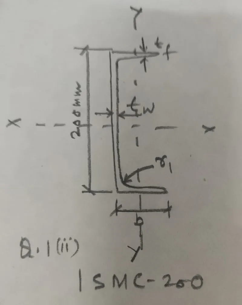
The properties of given section from steel table-
b=75 mm , `t_f`=11.4 mm , `t_w`=6.9 mm , `h_1`=77 mm = d
b/`t_f`= 75/11.4 =6.57 <9.4`epsilon` where `epsilon`=1 as above
Flange is Plastic section
d/`t_w`= 77/6.9 = 11.15 < 42`epsilon` where `epsilon`=1 as above
Web is plastic section
Result -Hence it is concluded that the given channel section is Plastic
Given section PG 1300 x 450 x 50 x 12
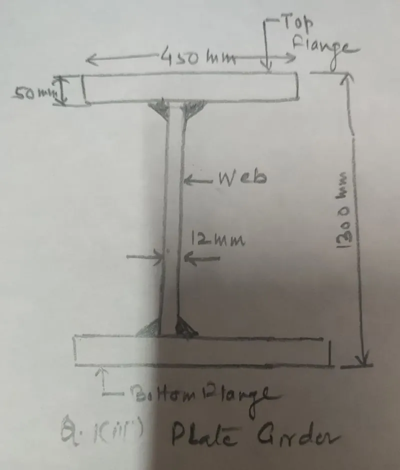
For flange- b/`t_f` where b=`b_f-t_w//2`= 450-12/2=219
b/`t_f`= 219/50 =4.38 <8.4`epsilon`for `f_y=250 N//mm^2``
where `epsilon= 1` as above
Flange is plastic section
For web- d/`t_w` =1200/12= 100 < 105`epsilon` (`epsilon`=1)
web is compact section
Result :Thus it is concluded that the section of the plate girder is compct
Double angle (Back to back) – 2 x ISA 75x75x6
b/t= 75/6 = 12.5
d/t = 75/6 = 12.5
b/t > `epsilon` but < 15.7 `epsilon`
so section is Semi compact
RHS - 150 x 100 x10
Internal element of compression flange
d = 150 - 2x10 = 130 mm , `t_w` = 10 mm
`d/t_w` = 130/10 = 13 ( section is plastic)
Builtup box – 1000 x 450 x 20 x 12
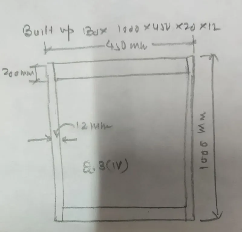
d = 1000- 2x20 = 960 mm , `t_w` = 12 mm
`d/t_w`= 960/12 = 80 < 84
Section is Plastic
Result :Thus it is concluded that the built up box section is Plastic
Q-2. Effective length problems
Calculate effective length of following Top chord beams (double angle) having length L1, L2, Vertical member (single angle) having length L3 and inclined member (single angle) having length L4.
Aim & Introduction- Effective length of various members in given truss are to be found out.
Truss is given in which top chord, vertical member and inclined members have been with their length have been marked with effective length are to be determined
Procedure( Solution)
Top chords with length `L_1 & L_2` are in compression which is continous so Effective length will be as follows-
`L_1` (Effective) = 0.85 `L_1`
`L_2`(Effective) = 0.85 `L_2` ( 0.7 L to 1.0 L )
`L_3`(Effective) = 1.0 L3 ( Vertical member in tension)
`L_4`(Effective) = 0.85 `L_4` ( Discontinous compression member)
Result :- It is concluded that the Member having length`L_1` , `L_2` is under compression are of effctive length 0.85 `L_1`, and 0.85 `L_2` , effective length of `L_3` is 1.0`L_3`and that of inclined member with length `L_4` is 0.85`L_4`
Q-2 Calculate effective length of rafter madeup of Builtup I section about major (X-X) and minor axis (Y-Y) having purlin spaced at 1.2 m.
Aim & Introduction: A truss is given with following data-
Span= 40m , Rise= 5.36 m , Angle of truss = 15 degree , Base of column are pinned joint
Procedure (Method) : Inclined Length of rafter AB in half truss = (40/2)/COS 15 =26.35 M
Let us assume that on half of the rafter is divided into 14 panels
Inclined Length of each panel = Inclined Length of PR/ No. of pannel= 26.35/14 = 1.882 m = 1822 mm
Effective length `L_(eff)` = 0.8 L= 0.8x 1822 = 1457.6 mm
Result : It is concluded that the Efeective length of the top chord of truss is 1457.6 mm
Q-5. Purlin design problem
Design channel purlin, considering sag rod at mid span for the roof truss having following data
- Span of truss : 20 m
- Spacing of Truss : 4 m c/c
- Roof slope : 20 degrees
- Spacing of purlin : 2 m
- Wind suction : 1 kN/m2
- Live Load : 0.75 kN/m2 ,Dead Load 1.4 kN/m2
Aim & Introduction- Design of channel purlin for roof truss
Span=20 m , spacing of truss= 4 m c/c , roof slope=20 degree , spacing of purlin = 2 m , wind suction = 1 KN/`m^2` , LL= 0.75 KN/`m^2` ,DL= 1.4KN/`m^2`
roof slop = 20 degree
Procedure (Method) -
1 ) Calculation of load-
Dead load perpendicular to the rafter = 1.4 Cos`20^@`
= 1.4x0.939 = 1.3146 KN/`m^2`
Dead Load per meter ( load/`m^2`x spacing of purlin) = 1.3146 x 2
=2.6292 KN/m
Live load perpendicular to the rafter = 0.75 Cos `20^@`
= 0.75 x0.939 =0.7042 KN/`m^2`
Live Load per meter ( load/`m^2`xspacing of purlin) = 0.7042 x 2 = 1.4084 KN/m
Wind load perpendicular to the rafter = 1.0 Cos `0^@`= 1.0 KN/`m^2`
Wind Load per meter ( load/`m^2`xspacing of purlin) = 1.0x2 = 2.0 KN/m
Load combination-
(DL + LL ) X 1 .5 = (2.6292 +1.408) X 1.5 = 6.0558 KN/m
(1.5 is partial load factor)
( DL + LL- WL ) X 1.2 = ( 2.6292 + 1.408- 2.0 ) x 1.2 = 2.4446 KN/m
( 1.2 is partial load factor )
Worst load combination = 6.0558 KN/m
Dead load parallel to the rafter = 1.4 Sin`20^@`
= 1.4x0.342 = 0.4788 KN/`m^2`
Dead Load per meter( load/`m^2`xspacing of purlin)=0.4788 x 2 = 0.9576 KN/m
Live load parllel to the rafter = 0.75 Sin `20^@`
= 0.75 x0.342 =0.2565 KN/`m^2`
Live Load per meter ( Load/`m^2`x spacing of purlin) = 0.2317 x 2 = 0.513 KN/m
Wind load parellel to rafter = 0.00
( DL+LL ) X 1.5 = 0.9576 +0.513+0.0) x 1.5 = 2.2059 KN/m
2) Bending moment calculation-
BM about Z-Z (`M_z`) = w`l^2//10`= 6.0558x`4^2//10`= 9.689 KN-m
( Purlin is continous over PR of truss)
BM about Y-Y (`M_y`) = w`l^2//10` = 2.2059 x`10^2//10`= 3.529 KN-m
3) Calculation of Shear Force-
`F_z` = Wl/2 = 6.0558x4/2 = 12.117 KN
`F_y`= Wl/2 = 2.2059x4/2 = 4.419 KN
4) Selection of trial channel section for purlin-
Selecting ISMC 200
properties of chosen section- h=200 mm, `b_f`=75 mm ,```t_f`=11.4 mm
`t_w`=6.1 mm, `h_1`= 150.2 , `I_(zz)`=1819.3 `mm^4`
`ZP_z`= `M_zxxgamma_(mo)``// f_y`+ (`2.5D``//b_f)`) `M_yxxgamma_(mo)``//``f_y`
= (9.689x`10^6`x1.1/250)+ (2.5x200/75) x ( 3.529x`10^6`x1.1/250 )
= 42631.6 + 6.6666x 15527.6 = 146147.89 `mm^3`
X- Coordinate C.G of the channel section
Refer above fig. (200x6.1)+ 2x11.4 x =2x(68.9-x)x11.4
1220+ 22.8x =1570.92-22.8x
x= 350.92/45.6 = 7.69 mm
`ZP_Y` = (600x6.1)(6.1/2+7.69)+2[(68.9x11.4)(68.9/2-7.69)
= 39308.4+42037.819 =81346.2 `mm^3`
5 ) Section classification-
d/`t_w` 150.2/6.1 24.62 <42`epsilon` where `epsilon`=`(250/f_y)^0.5`
For mild steel f_y =250 N/`mm^2` so`epsilon`=1
Web of section is Plastic
b/`t_f`= 75/11.4=6.57 < 9.4 `epsilon` so outstanding flange is also plastic
Thus the channel section is Plastic
7 ) Shear capacity of the section-
About Z axis
`V_d`= `A_vxxf_(yw)``//sqrt3xxgamma_(mo)`=200x6.1x250/1.732x1.1
= 160.088 KN
0.6 `V_d` = 0.6x 1600= 96 KN > `F_z` =12.117 KN ( Safe)
About Y axix-
`V_d`=`A_vxxf_y//sqrt3xx gamma_(mo)`=2x75x11.4x250/1.732x1.1 =224.38 KN
0.6x`V_d`= 0.6x 224.38 = 134.628 KN> `F_y`= 4.419 KN
8 ) Design moment in Z direction `M_dz`= `beta_bxx ZP_zxxf_y`//`gamma_(mo)`
= 1x146147x250/1.1= 33215227 N-mm= 33.215 KN-m > `M_z`=9.689 KN
Safe in moment in Z direction
`M_(dy)`= `beta_bxxZP_yxxf_y` `gamma_(mo)`
= 1x81346.2x250/1.1 =18487772 N-mm= 18.48 KN-m> `M_y`= 3.529 KN-m
Safe in moment in Y direction
9) Over all strength condition-
`M_z/M_dz+M_y/M_dyle1`
9.689/33.215+3.529/18.48 = 0.291+0.190 = 0.481< 1 ( OK)
10) Check for deflection-
Actual deflection = `(5WL^4)/(384EI)`=5x1.4084x `(4xx10^3)^4`/384x2x`10^5`x1819.3x`10^3`= 12.89 mm
Permissible max deflection as per table-6 of IS 800 at page-31 for Live load with Elastic cladding = L/240 = 4000/240= 16.66 mm
Actual deflection (12.89 mm) < permissible deflection ( 16.66 mm) ( OK)
Safe in deflection
Result :- It is concluded that for purlin of truss ISMC 200 section is safe in shear, moment , over all strength and deflection.
Q-4. Moment capacity determination problem
Select a standard hot rolled section for the beam which is simply supported of length 6 m spaced at 3 m c/c, carrying a floor Dead load of 5 kN/m2 (including Self weight) & Live load of 6 kN/m2 and a concentrated load of 100 kN at mid span of beam. The beam is laterally unrestrained and assumes bearing length of 50 mm
Tip steps:
- Calculate maximum bending moment & required plastic modulus
- Select suitable trial section
- Calculate design shear force and design shear strength
- Check design capacity of the section
- Check for deflection, web buckling, bearing
Aim & Introduction- Determination of moment capacity of a simply supported beam.
- Hot rolled section for beam is to be choosen
- Beam is simply supported
- Length of Beam = 6m
- Spacing of Beams = 3m c/c
- Dead load on beam = 5 KN/`m^2` ( including self weight)
- Live load on beam= 6 KN/`m^2`
- Concentrated load on beam = 100 KN
- Beam is laterally unsupported/unrestrained
- Bearing length = 50 mm
- Assume grade of steel Fe 410 , Partial safety factor = 1.1
Procedure-
1) Load calculation-
DL = 5x 3 = 15 KN/m
LL = 6x3 =18 KN/m
Total UDL = 33 KN/m
Point load = 100 KN at center of span
2) Shear force & Moment calculation-
`sum V`=0 `R_A+R_B=`33x6+100=298 -------(1_
Taking moment about A `R_B`xx`6`= 100x3+33x6x3
`R_B`=149 KN , `R_A`=149 KN By symmetry
SF at B =-149 KN
SF at C = 50 KN
SF at A = 149 KN
Max SF = 149 KN
Factored shear Force V = 1.5 x149 =223.5 KN
Moment calculation-
`M_B = `R_Bxx0= 0` , `M_C`= -149x3 +33x3x1.5 = 298.5 KN-m
`M_A`=149x6-100x3-33x6x3 = 0
Factored moment M= 1.5x 298.5= 447.75 KN-m
3 ) Section modulus-
`Z_p`(required) = `Mxxgamma_(mo)//f_y`= 447.75``x`10^6`x1.1/250 =1970.1`cm^3`
3) Choosing section ISWB 600 @ 133.7 Kg/m, Section properties from steel table-
Shape factor `Z_p/Z_e`= 1.14 so `Z_e`(required)= 1728.15 `cm^3`
`Z_p` ( provided) = 4035.6`cm^3`> `Z_p`(required) =1970.1`cm^3`
`Z_e`(provided)= 3540 `cm^3` ,`r_1`= 17 mm , h = 600 mm
`b_f`= 250 mm , `t_f`= 21.3 mm , `t_w`= 11.2 mm
`I_(XX)` = 106198 , `I_(YY)` = 4702.5 `cm^4` , `r_(yy)`= 52.5 mm
d= h-2(`r_1`+`t_f`) = 600 -2(17+21.3) =523.4 mm`
4) Classification of section-
`(b_f//2)/t_f` = 125/21.3 = 5,86 < 9.4
d/`t_w`= 523.4/11.2 = 46.73 < 84
Hence the section is Plastc
5) Calculation of shear capacity of section-
`V_d= ( A_vxxf_y)/(sqrt3xxgammamo)`= 600x11.2x250/1.732x1.1 = 881797 N
`V_d`= 881.79 KN > V = 223.5 KN (Safe in Shear) (OK)
0.6`V_d` = 0.6x 881.79 = 529 KN > V = 223.5 KN
Hence low shear
6) 1st Mehod for finding Design capacity of moment- ( By Intrpolation method)
Design strength for laterally unsupported beam is-
KL/`r_y` = 6000/52.5= 114.28
`h_f/t_f` (600- 21.3)/21.3 =27.16
`f_(cr,b)` from table 14 of IS 800 (By Interpolation)
`f_(cr,b)` = 240 N/`mm^2`
`lambda_(LT)`=`sqrt(f_y/f_(cr)` =`sqrt(250/240)` = 1.02
`phi_(LT) = 0.5[ 1+alpha_(LT) (lambda_(LT)-0.2)+ lambda_(LT)^2]`
= 0.5 [ 1+ 0.21 (1.02- 0.2) + 1.02x1.02] 1.1063
`chi_(LT)`= `1/(phi_(LT)+ [phi_(LT)^2- lambda_(LT)^2]^0.5 )le1.0`
=`1/(1.1063+(1.1063^2-1.02^2)^0.5`= 0.652 <1 ( OK)
`f_(bd)= chi_(LT)xxf_y//gamma_(mo)`
= 0.652x250/1.1 = 148.18 N/`mm^2`
`M_d = beta_bxxZ_pxxf_(bd)`
= 1.0 x 4035.6 x1000 x 148.18 = 598 KN-m > M (447.75 kn-M)
Section is safe in bending stress
Thus moment capacity of beam = 598 KN-m
2nd Method for finding moment capacity of beam using formulae given in IS 800: 2007
As the beam is laterally unstrained, the design is found by calculating the lateral tortional buckling moment-
`M_d = beta_bxxZ_pxxf_(bd)`
`beta_b` =1 for Plastic and Comopact section
`f_(bd)` = design bending compressive strength =`chi_(LT)xx f_y// gamma_(mo)`
where `chi_(LT)` is bending stress reduction factor to account for lateral tortional buckling
`phi_(LT)` = 0.5[ `1+alpha_(LT)` `(lambda_(LT) - 0.2)`+ `lambda_(LT^2`]`
Design Bending strength of laterally unsupported beam
`M_(cr) = sqrt(pi^2EI_y//(KL)^2(GI_t+(pi^2EI_w)/(KL^2) )`
`G = (E/(2(1+mu)))` = 2x`10^5`/2(1+0.3) = 9.7087x`10^4 N//mm^2`
`I_t = tortional constant sum 'b_ixxt_i^3//3` for open section
`I_t` = [ 2x 250x `21.3^3`/3 + ` (600-21.3)x `11.2^3/3`]
= [ 1610599.5+ 271010.61 = 1881610.11 = 1.882 x`10^6 mm^4`
`I_w`(wrapping constant) = `(1-beta_f)beta_fxxI_yxxh_f^2`
= ( 1-0.5)x0.5x4702.5 `10^4`x`578.7^2` =3.937x`10^12``mm^6`
`M_(cr)`= `sqrt(pi^2xx2xx10^5xx4702xx10^4//6000^2
(9.7087xx10^4xx1.882xx10^6+pi^2xx2xx10^5xx3.937xx10^12//6000^2`
`M_(cr)` = 304. 33 KN-m ( 1012.926)
`lambda_(LT)` =`Non dimensional slenderness ratio `nbsp;= sqrt(beta_bxxZ_pxxf_y//M_(cr)`
=`sqrt(1.0xx4035.6xx10^3xx250//1012..926xx10^6` = 0.99`
`phi_(LT) = 0.5[ 1+alpha_(LT) (lambda_(LT)-0.2)+ lambda_(LT)^2]`
= 0.5[ 1+ 0.21 (1.82-0.2) + `(0.998)^2`] = 1.1681
`alpha_(LT)` = Imprefaction factor for lateral buckling = 0.21 for I sction from table 13 (a)
`chi_(LT)`=`Design bending strength reduction factor
`chi_(LT)`= `1/(phi_(LT)+ [phi_(LT)^2- lambda_(LT)^2]^0.5 )le1.0`
=`1/(1.1681+(1.1681^2- 0.99^2)^0.5`= 0.802
`f_(bd) = chi_(LT) xxf_y//gamma_(mo)`
= 0.802x250/1.1 = 182.44
`M_d= beta_bxxZ_pxx f_(bd)` = 1.0x 4035.6 `xx10^3`x182.44/1.1
= 669.34 KN-m
Optional ( Not needed as per question)
7) Check for deflection- `delta`= `5/384xx(wl^4)/(EI)`w`l^3//48`EI
= 1/2x`10^5`x 106198x`10^4`[5x18x `6000^4`/384+ 100x`6000^3`/48]
= 1.43 mm 21.18 mm = 22.61 mm
Permissible max deflection as per table-6 of IS 800 at page-31 for Live load with Elastic cladding
= L/240= 6000/240 = 25 mm > 22.61 (OK) , Safe in deflection
8) Check for Web buckling-
d/`t_w`= 523.4/11.2 = 46.73 < 67`epsilon` (OK)
So no need of checking for web buckling
Check for Web Crippling-
`n_1`= 2.5x(`t_f+r_1`) = 2.5(21.3+17) = 95.75mm
As per cl.8.7.4 of IS 800 :2007 Page No.67
`F_w`= (`(b_1+n_2)`xx`t_w `xx`f_y//`gamma_(mo)`
where `b_1`=length of stiff bearing =50 mm
`n_2`= length of load dispersion
= (50+95.75)x11.2x250/1.1
371000 N = 371 KN > V = 223.5 KN (OK)
section is safe in bearing
Result- Thus it is conclued that the beam ISWB 600 @ 133.7 Kg/m, is capable to resist Bending moment of 548.7 KN-m safely
Q-3. Deflection of a beam problem
Q (i) Calculate deflection at the centre of the beam shown below. EI = 20 x 106 Nm2
Aim & Introduction- Deflection at the center of the beam is to be found out
Given- EI = 20x`10^6 N-m^2`, Beam witt UDL of 6 N/m and two point loads each of 100 N symmetrically placed
Procedure- (Refer figure given below)
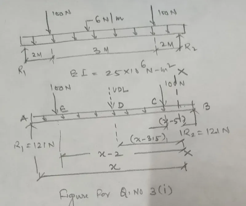
`R_1+R_2` =100+100+6x7 = 242 --------------(1`
Taking Moment about B `R_2`x7 = 100x5+100x2+42x3.5 = 847\
`R_2` =121 N , From eqn (1) `R_1` = 121 N
Considering Moment about X-X
`M_(XX)`- 121 (x) + 100(x-2) + 6(x)(x/2)+100(x-5) =0
`M_(XX)`= 121 (x) - 100(x-2) - 6(x)(x/2) - 100(x-5)
`EI (d^2y//dx^2)` = 121 (x) - 100(x-2) - 6(x)(x/2) - 100(x-5)
EI (dy/dx) = 121(`x^2/2`) +`C_1` - 100 `(x-2)^2/2` -6(`x^3/6`) -100 `(x-5)^2/2`
EIy = 121 (`x^3/6`) + `(C_1x)`+`C_2` - 100 `(x-2)^3/6` -6 (`x^4/24`) -100 `(x-5)^3/6`
0 = 6917.66 +7`C_1`- 2083.33 -600.25 -133.33
7`C_1` = 2083.33+600.25+133.33 - 6917.66
`C_1` = - 4100.42 /7 - 585.77
Applying boundary conditions- x=0, y=0 then `C_2`=0
x=7, y=0 this gives `C_1`= -585.77
EIy = `121 (x^3/6)`- 585.77(x)- 100 `(x-2)^3/6` -6`(x^4/24)`-100 `(x-5)^3/6`
For max. deflection x= 3.5 ( due symmetrical loading and SF =0 at x = 3.5 m
EIy = 864.64 - 2050.19 - 56.25 - 37.51 = - 1279.31
EIy = -1279.3
y = -1279.31/EI = -1279.31x1000/20x`10^6` = 0.0639 mm
Result - It is concluded that the deflection at the mid point of the beam shall be maximum due to the symmetry of loads which is = 0.0625 mm
Q 3 (ii)- Calculate deflection at the centre of the beam shown below. EI = 25 x 106 Nm2
Aim & Introduction- Deflection at the centre of the beam is required
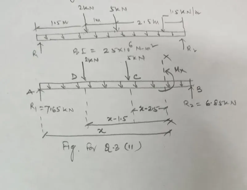
A beam with EI = 25x `10^6 Nm^2` having UDL @ 1.5 KN/m and point load of 2 KN & 5 KN is given
`R_1+ R_2` = 2+5+ 1 .5x5 = 14.5 --------(1)
Taking moment about A
`R_2`x5 =5(2.5) + 2 (1.5) +7.5(2.5)
`R_2` = 34.25/5 = 6.85 KN
From equation (1) we get `R_1` = 14.5 - 6.85 = 7.65 KN
Taking moment about X-X
`M_x` - 7.65 (x) +2( x-1.5) + 1.5(x) (x/2) + 5(x-2.5) = 0
`M_x` = 7.65 (x) - 2( x- 1.5) -1.5 (x)( x/2) - 5( x- 2.5)
EI (`(d^2y)/ (dx^2)`= 7.65 (x)-2 ( x-1.5) - 1.5 (x)(x/2)-5 ( x- 2)
Integrating-
EI (dy/dx) = 7.65 `(x^2/2)` +`C_1`- 2`(x-1.5)^2/2`-1.5`(x^3/6)`-5`(x-2.5)^2/2` -------------------------(2)
Now differenciating equation (2)-
EI y = 7.65 `(x^3/6)`+ `C_1(x)`+`C_2`-2`(x-1.5)^3/6`- 1.5`(x^4/24)`- 5`(x-2.5)^3/6` ---------------(4)
Applying boundary conditions x=0 , y=0 in equation (4) which gives `C_2`=0
Now using x= 5 , y =0 in equation -4)
159.75 + 5`C_1`- 42.875- 39.0625 - 13.02
`5C_1` = 42.875 +39.0625+13.02- 159.75 = - 64.7925 `C_1` = - 64.7925/5 = - 12.96
Substituting the values of `C_1 & C_2` in equation (4), we get
EI y= 7.65 `(x^3/6)` -12.96 (x) -`(x-1.5)^3`-1.5`(x^4/24)`-5`(x-2.50)^3/6`
Deflection at the middle where 5KN force is acting,
substituting x= 2.5 m in equation (4)-
EI y= 19.92 -32.4 -1.0 -2.44 = - 15.92 KN `m^3`
EI y at x = 2.5 m = - 15.92`xx10^9` N `mm^3`
y at centre = - 15.92`xx10^9`/ 25`xx10^6xx10^3` = - 0.6368 mm
Result - It is concluded that deflection at the centre due to given loading arrangement of beam is 0.6368 mm ( -ve sign indicate that the deflection is below the X axis
Q 3(iii) A simply supported beam is 10 m long with udl of 10 kN/m Calculate the Flexural stiffness (EI) of the beam which limits the deflection to 5 mm at the middle.
Aim & Introduction- Flexural stiffness (EI) of the beam is required to be calculated.
Beam is simply supprted , span = 10 m , UDL = 10KN/m , Deflection to be limit up to 5 mm
Procedure -
Maximum deflection a the middle due to UDL on simply supported beam
`delta` =`(5wl^4)/(384 EI)`
5X`10^-3` = 5x 10x`10^3`x `10^4`/ 384 EI
EI = 26x`10^7 Nm^2`
Result - Thus it is concluded that in order to restrict the the deflection to 5 mm the value of Flexural stiffness (EI) of the beam should be 26x`10^6 Nm^2`