Week 2 Challenge
`mm^2` Q-1
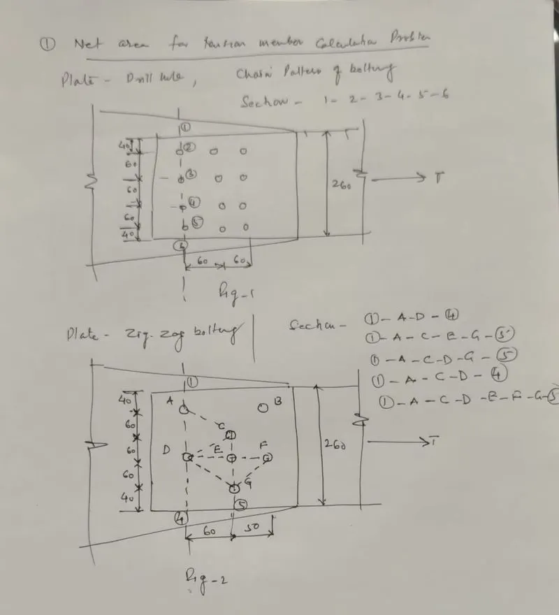
Aim : Net section Area of tension member e.i. plate is required to be calculated.
Introduction : When plate is used in any steel structure it is subjected to tension whch will be safe only when stress developed on it is lesser than permissible stress. Tihe plate may fail due to gross area yielding where after yield stress excessive deformation of material i.e. strain developes so member become unserviceable so the member needs to be checked for Gross Area yielding before put in use . If plate has hole in it for bolting or Rivetting then net area of critical section for resisting stresses is reduced so member may fail due to net area Rupture . In this case member is required to be checked from the criteria of rupture of net area failure before put in use. Another mode of failure of the member is Block shear failure where the complete block of member may fail in shear or in tension so member is also required to be checked in this mode of failure. Strength of the member will be the least value of the three mode of failure. Here we assume partial safety factor in yielding as 1.1 while in rupture where ultimate stress are considered this partial safety factor is considered as 1.25.
Solution-
Net area along section 1-2-3-4-5-6 ( Chain patter of holes)
`A_n = ( b-n times dia of bolt holes) times t`
= (40+60+60+60+40 - 5x 20) x20 = 3200 `mm^2`( clearence =2 mm for 18 mm dia bolt)`
Net area = 3200 `mm^2`-----------Ans
Result :- In chain patter of holes, we have considered the section having maximum number of holes. In the given problem there are three rows oh holes cosisting of 4 holes in each row. So the critical section shall be any of the row of holes with 4 holes with minimum net area.
Plate-Zig-zag bolts
Along section 1-A-D-4
A_n = (b-nh)t +s^2 /4g times t`
=`(260-2 times20) 20`
= 4400 mm^2 ---------(a)
Along 1-A-C-E-G-5
A_n = (b-nh)t +s^2 /4g (t)`
= (260-4 times 20) times 20 + 1 times 60^2 /(4 times 60) times 20`
= 3900 mm^2 ---------(b)
Along 1-A-C-D-4
A_n = (b-nh)t +s^2 /4g (t)`
= (260-3 times 20) times 20 + 2 times 60^2 /(4 times 60) times 20`
= 4600 mm^2 ---------(c)
Along 1-A-C-D-G-5
A_n = (b-nh)t +s^2 /4g (t)`
= (260-4 times 20) times 20 + 3 times 60^2 /(4 times 60) times 20`
= 4500 mm^2 ---------(d)
ALONG 1-A--C-D-E-F-G-5
A_n = (b-nh)t +s^2 /4g (t)`
= (260-6 times 20) times 20 +1x times 60^2 /(4 times 60) times 20`+ 1X times 50^2 /(4 times 60) times 20`
= 3308.33mm^2 ---------(d)
Net area is leasr along section 1-2-5-6-7 which is 3900 mm^2
`A_n`= 3308.33 `mm^2`--------------Ans
Result :- In zig-zag patter of holes critical section with least net area is selected in such away that it includes maximum holes in zig-zag fashion including inclined portion. This is done by choosing possible pattern of section and evaluating the net area in each section . The section which give least area is considered as critical section.
Q-1 ,Fig.3 ( Net area calculation) Angle section 200x100x12 with M20 bolt
Given nominal dia of bolt d =20 mm ; Dia of hole `d^'`=22 mm
Considering net area section along 1-2-3-4-5
As per fig 3 given below
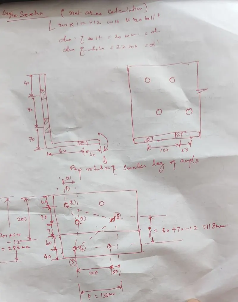
`A_n` =[( 40+90+70+60+40_12 ) -3x 22+( `50^2//4times 90 +50^2//4times 118` )]x12 = 2517.24 `mm^2`
Considering net area section along 1-2-6-4-5
[( 40+90+70+60+40_12 ) -3x 22+ (`150^2//4times 90 +150^2//4times 118` )]x12 = 3986.03 `mm^2`
A minimum = 2517.24 mm^2` along section along 1-2-3-4-5--------Ans
Result:- Here there is a zig-zag patter of holes consisting of both the legs so in order to find the critical section outstanding leg of the angle needs to be rotated to find the gauge and end distances. Thickness of angle is reqired to be deducted while calculating gauge distance covering two legs.
3. Determine section size for given tensile load
Design a single angle member of length 5m to carry axial tensile force of 500 kN. Yield strength fy of the material to be considered is 350 N/mm2.
Aim :- An angle member for tensile force of 500 KN is required to be designed
Introduction :- First of all given tensile force shall be multipied by a factor of safety 1.5 to come out with disign force considering safety against unforeseen additonal force that may crop up during the design life of the member/structure. Required Gross area of the member is calculated considering the gross area yielding using partial safety factor as 1.1 for yiel stresses. Member is selected from steel tabl 30-40% more area for compensating holes for bolting/Rivetting which will redue the area. Member is checked for three possible mode of failure viz yielding of the gross section, rupture of the critical section, block shear failure .Least of the three strength shall be considered as design strength of the member. If least of these value is more than the design/ ultimate load then Member is safe
Solution:
l= 5m ; Axial tensil force T= 500 KN ; `f_y = 350 N//mm^2`
`T< ( T_dg, T_dn, T_db)`
Design strength of the member under axial tension is the lowest of design strength due to-
(i) yielding of the gross section `T_dg`
(ii) rupture of the critical section `T_dn` and
(iii) block shear failure `T_db`
`T_u = 1.5 times T`
= 1.5 X 500 = 750 KN
`A_g = T_u times gamma_mo//f_y`
=`750 times 1.1 times 10^3//350`
= 2357.14 `mm^2`
`lambda=` = 350 ( Assumed)
`lambda=`kl/r = 5000/r= 350
r= 14.28
Choosing single angle section ISA 120x120x12 with gross area A = 2750 `mm^2`
`r_min=`23.5 mm
`lambda=`kL/``r_min` = 5000/23.5 = 212 < 350 ( O.K)
`T_dg = f_y times A_g//gamma_mo`
=`350 times 2750//1.1
= 875 KN >750 KN ( safe, OK)
Assumr M20 bolt so d=20 mm, `d_0=22 mm` assume grade of bolt 8.8
so `f_ub=600 N//mm^2`
`end distance = 1.5x `d_o`=1.5x22 = 33 mm
pitch distance = 2.5x`d_o`= 2.5x22 = 55 mm
Assuming 3 bolts of 20 mm diameter
`T_dn= 0.9f_u A_nc//1.25 + beta f_y A_go//1.1`
`A_nc=` ( 120-6-22)x 12 = 1104 `mm^2`
`A_go=`( 120-6)x12= 1368 `mm^2`
w= 120 mm, `b_s= w+w_1-t` = 120+87-12= 195 mm
`L_c=`2x55 = 110 mm, `f_u= 600 N//mm^2` ; `f_y=350 N//mm^2`
`beta = 1.4-0.076 [ (w//t) (f_y//f_u)(b_s//L_c)]`
= 1.4- 0.076x[120//12)(350//800)(195//110) = 0.81`ge 0.7`( O.K)
`f_utimes gamma_mo//f_ytimes gamma_m1`
= 800 x1.1/ 350x1.25= 2.01 `ge beta`( O.K)
`T_dn = 0.9 A_nc f_u//gamma_m1 +beta A_go f_y//gamma_mo`
=( 0.9 x1104x800/1.25) + 0.81 x1368x350/1.1 = 956.423> T (OK)
`T_db1=(A_vg timesf_y//sqrt3 gammam0) + (0.9 A__tn times f_u//gamma_m1)`
AND1
`T_db2=( 0.9 A_vn timesf_u//sqrt3 gammam1) + ( A__tg times f_y//gamma_m0)`
`A_vg=` gross area at shear =(33+3x55)x812 = 2376 `mm^2`
`A_vn=` Net area in shear = ( 33+5x55- -3.5x22)12= 1716 `mm^2`
`nbsp; `A_tg=` Gross area in tension= (120-33)x12= 1044 `mm^2`
`A_tn=` Net area in tension =( 120-33)-22x0.5)x12 = 912 mm^2`
`T_db1=(A_vg timesf_y//sqrt3 gammam0) + (0.9 A__tn times f_u//gamma_m1)`
= 2376x350/`sqrt3`x1.1 + 0.9x912 x800/1.25
= 436.489 + 596.94 = 1033.43 KN > `
`T_db2=( 0.9 A_vn timesf_u//sqrt3 gammam1) + ( A__tg times f_y//gamma_m0)`
= 0.9 x1432x800/`sqrt3`x1.25 + 1044x350/1.1 ( `F_u = 800 N//mm^2 say)`
= 476.23 + 332.18 =808.41 KN > `T_u` ( safe)
Result:- Srength in yielding of gross section is 875 KN, Strength in rupture of critical section has been found as 956.423 KN and strength in block shear failure is 808.41 KN. The design strength is cinsidered least of the three values i.e 808.41 KN which is greater than design tension of 750 KN, hence selected angle section is safe.
Hence the chosen angle section is safe in gross section yielding, net section rupture and block shear failure
Determine section size for given tensile load
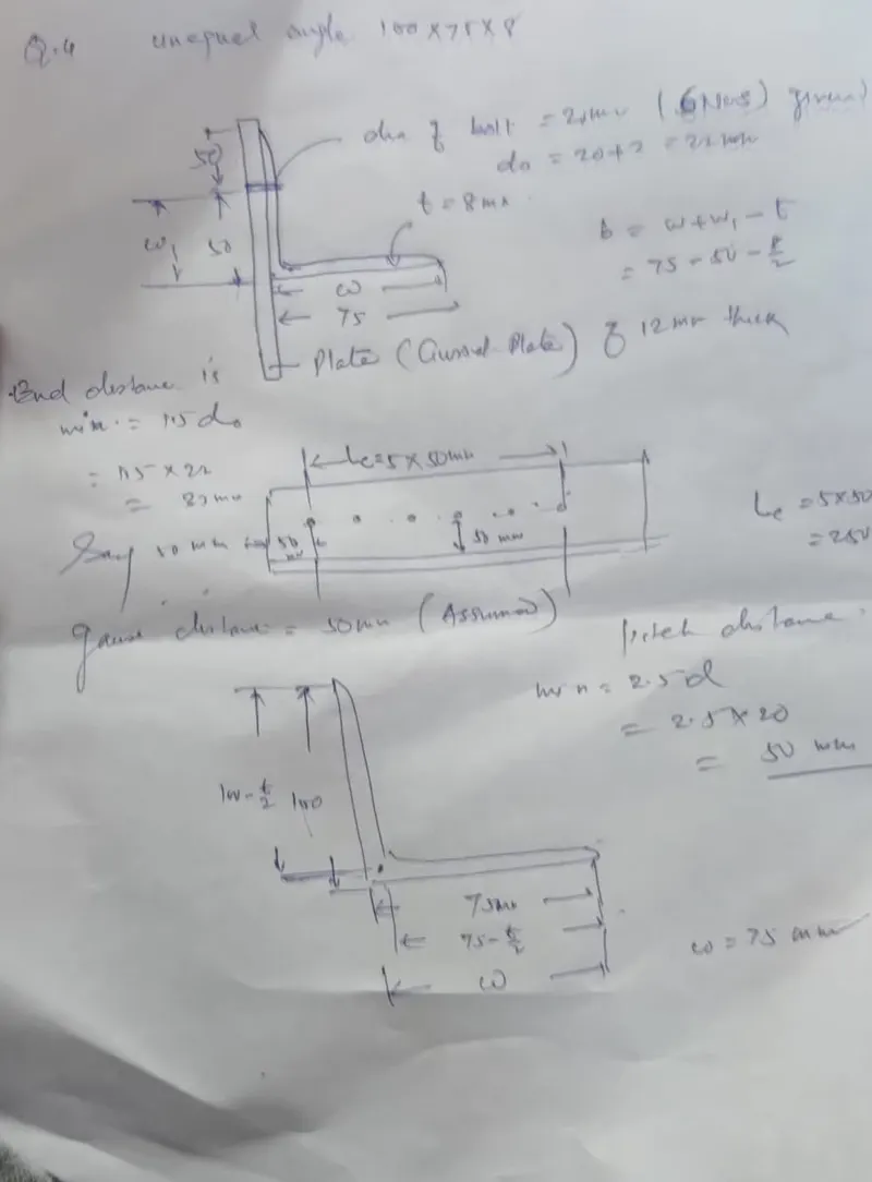
Q-4 A single unequal angle 100 X 75 X 8 mm is connected to a 12 mm thick gusset plate at the ends with 6 nos. 20 mm diameter bolts to transfer tension. Determine the design tensile strength of the angle. If the gusset is connected to the 100 mm leg
Aim : To find design tensile strength of a single unequal angle 100x75x8 mm connected to 12 mm thick gusset plate with 6 nos 20 mm diameter bolts .
Introduction :- We have to determine what is the maximum tensile strength the given member can resist. For the given problem we have to analyse / check the given member ( amgle section connected witg gusset plate with longer leg) for three possible mode of failure viz yielding of the gross section, rupture of the critical section, block shear failure . Least of the three strength shall be considered as design strength of the member. Grade of steel has been assumed as Fe410 with Fy= 250 MPa. Partial safty factor in case of yielding stress and ultimate stress have been assumed as 1.1 and 1.25 respectively.
Solution-
Thickness of leg= 8mm; thickness of plate = 12 mm ; d= 20 mm ; `d_o`= 22mm
`gamma_mo`= 1.1 ; `gamma_mo`=1.25
1- Design strength due to yielding of gross section
`T_dg = f_y times A_g//gamma_mo`
Asume grade of steel Fe 410 that is Fu = 410 N/sqmm ; Fy= 250 N/sqmm
`A_g=` (100-4+75`-4) 8 = 1336 `mm^2`
`T_dg= 250 times 1336//1.1 = 303.63 KN
The design strength due to rupture , `T_dn` is given by :
`T_dn = 0.9 A_nc f_u//gamma_m1 +beta A_go f_y//gamma_mo`
whewe `beta= 1.4 -0.076 (w//t)(f_y//f_u) (b_s//L_c_)les (f_u//gamma_m1//f_y//gamma_mo)ge0.7`
`A_nc=` ( 100-4-22-)x 8 = 592 `mm^2`
`A_go=`( 75-4)x8 = 568 `mm^2`
w= 75 mm, `b_s= w+w_1-t` = 75+50_4= 121 mm
`L_c=`5x50 = 250 mm, `f_u= 410 N//mm^2` ; `f_y=250 N//mm^2`
`beta = 1.4-0.076 [ (w//t) (f_y//f_u)(b_s//L_c)]`
= 1.4- 0.076x[(75//8)(250//410)(121//250) = 1.189`ge 0.7`( O.K)
`f_utimes gamma_mo//f_ytimes gamma_m1`
= 410 x1.1/ 250x1.25= 1.44 `ge beta`( O.K)
`T_dn = 0.9 A_nc f_u//gamma_m1 +beta A_go f_y//gamma_mo`
=( 0.9 x592x410/1.25) + 1.189x121x250/1.1 = 510.728
3- Design strength in block shear-
`T_db1=(A_vg timesf_y//sqrt3 gammam0) + (0.9 A__tn times f_u//gamma_m1)`
AND1
`T_db2=( 0.9 A_vn timesf_u//sqrt3 gammam1) + ( A__tg times f_y//gamma_m0)`
`A_vg=` gross area at shear =(50+5x50)x8 = 2400 `mm^2`
`A_vn=` Net area in shear = ( 50+5x50- -5.5x22)8= 1432 `mm^2`
`A_tg=` Gross area in tension= 40x8= 320 `mm^2`
`A_tn=` Net area in tension =( 50-22/2)x8 = 312`mm^2`
`T_db1=(A_vg timesf_y//sqrt3 gammam0) + (0.9 A__tn times f_u//gamma_m1)`
= 2400x250/`sqrt3`x1.1 + 0.9x312x410/1.25
= 314.928 + 102.336 = 417.268 KN
`T_db2=( 0.9 A_vn timesf_u//sqrt3 gammam1) + ( A__tg times f_y//gamma_m0)`
= 0.9 x1432x410/`sqrt3`x1.25 + 400x250/1.1
= 244.068 + 90.909 =334.977 KN
Therefore Tensile strength of member( Angle) is least of the value calculated against 1 ,2 &3
Tensile strength = 303.63 KN ------ANS
Result :-Srength due to yielding of gross section is 303.63 KN, Strength in rupture of critical section has been found as 510.728 KN and strength in block shear failure is 334.977 KN. The design strength is considered least of the three values i.e 303.63 KN hence the given angle section is safe for tensle load of 303.63 KN.
2. Sag rod design problem
Design a sag rod as shown in Figure below. Purlins are supported at 1/3rd points by sag rods. Assume centre to centre distance of Rafter spaced at 8 m , spacing of purlin = 1.2 m, Self weight of roofing (including thermal insulation)= 80 kg/m2 , Wind pressure intensity = 150 kg/m2,Slope of rafter = 15 degrees, Live Load =75 kg/m2. Assume self weight of purlin as 100 kg/m.
Tip Steps :
- Calculate total gravity load (DL & LL) on the purlin
- Calculate Wind load acting on the purlin. Note that wind load acts perpendicular to the member.
- Resolve and calculate the load acting parallel to the roof
- Force contribution to each sag rod is calculated
- Calculate required net area and chose a desired sag rod size
Aim :- Disign of sag rod
Introduction :- Sag rod is a member which connect purlin to provide lateral stability. It is designed as atension member. Dead load of members, Live load act on member vertically downward due to gravity . we need forces pon purlin perpendicular and parallel to the principle rafter or purlin or roof. Forces will be resolved into two components out of which forces parallel to the roof shall be taken by sag rod for which it is to be designed. Sag rod shall be checked for gross area yielding as there will not be holes on sag rod so failure due to rupture of critical section and block shear failure is over ruled and need not be checked. Grade of steel is considered as Fe250 so Fy shall be 150 MPa
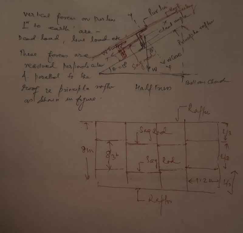
Solution- Refer figure above
Calculation of load on purlin due to one pannel -( 1.2 m spacing of purlins and 8 m span)
Self weight of roofing = 80 Kg/sqm = 80x 8 x1.2 = 768 Kg
Wind pressure = 150 Kg/sqm = 150x8x1.2= 1440 Kg
Live Load = 75 Kg/sqm = 75x 8x1.2 = 720 Kg
Self wt of purlin = 100 Kg/sqm = 100x8x1.2 = 960 Kg
Resolving the load parellel to the roof-
Self weight of roofing pareliel to the rafter = 768 Sin 15 =768x0.259 = 198.912 Kg
Wind perpendicular to the rafter = 1440 perpendicular to roof
Live Load pareliel to the rafter = 720 Sin15 = 720x 0.259 = 186.48 Kg
Self wt of purlin pareliel to the rafter = 960 Sin15 = 960x0.259= 248.64 Kg
Total force on purlin parallel to roof i.e. on each pannel = 634 .032 Kg
Factored Force = 1.5x 634 .032= 951.048
say 952 Kg = 9520 N
9520 N FORCE will be on intermediate pannel and half of it will be on end pannel but for designing sag rod we shall consider force = 9520 N
Force on each sag rod parallel to the roof = 1/2 x 9520 = 4760 N
( Sag rod are at L/3 between the span of purlin or between two consecutive truss which mean two sag rod will be there in each pannel)
`F_y//gamma_mo= P_u/A_g
250/1.1 = 4760/A_g
A_g = 4760x1.1/250 20.944 sq mm
Using 6 mm rod as sag rod with gross area of cross section = 28.26 sqmm
Result :- Sag rod connecting purlinis designed as 6 mm rod to take the tension and is safe in gross yielding stress. This sag rod will be connected with purlins through nut and bolt and as such there will nt be any hole in rod so other mode of failure of sag rod are will not be taking place.