Week 3 Challenge
Q- 1. Effective length factor determination problem
Height of column is 10 m and it is effectively restrained in mid height in one direction (in Z direction) but free to move in other direction (Y direction). Bottom of column is Fixed and top of column is Free.
Aim: Effective length factor of the member is required to be Calculated
Introduction ( Given & assumed data)-
- Height of Column= 10 m,
- Column is Effectively Restrained in Mid height in one direction( In Z direction),
- Column is free to move in other direction ( In Y direction)
- Bottom of the Column is fixed and Top of the Column is Free
Procedure (Solution) : 10 m vertical is fixed at bottom and restrained at 5 m ( mid height) in Z direction that is column is not free to move but it is free to move in X direction at mid height height as well as from the top of the column. Thus in the given condition the column will behave as a cantilever, hence Effective length fact K=2
Result : It is concluded that base of the column 1s fixed but other end at mid height is free in X direction so it is like a cantilever hence Effective length factor K=2
Q-1, Figure-a, braced frame and shear wall
Aim: Effective length factor of the column is required to be Calculated
Introduction ( Given & assumed data)-
- The Portal frame is divided into 04 pannel with shear wall upto two pannels
- Column and base joint is hinged
Procedure ( Solution) : Column End connections are hinged and hinged . Therefore k=1
Result : It is concluded that ends of the column are hinged and hinged so Effective length factor K=1
Q-1, Figure-b, Unbraced frame with Pined Base
Aim: Effective length factor of the column is required to be Calculated
Introduction ( Given & assumed data)-
- The Portal frame is divided into 03 pannel
- Column height is divided in 3 equal part by horizontal beams
- Column and base joint is hinged
Procedure ( Solution) : Column End connections are fixed and hinged . Therefore k=1/`sqrt2`
Result : It is concluded that ends of the column are fixed and hinged so Effective length factor K=1`sqrt2`
Q-1 ,Figure C, Unbraced frame with fixed base
Aim: Effective length factor of the column is required to be Calculated
Introduction ( Given & assumed data)-
- The Portal frame is divided into 03 pannel
- Column height is divided in 3 equal part by horizontal beams
- Column is fixed with base
- Procedure (Solution) : Column connections are fixed and fixed . Therefore k= 0.5.
- Result : It is concluded that ends of the column are fixed and fixed so Effective length factor K=0.5
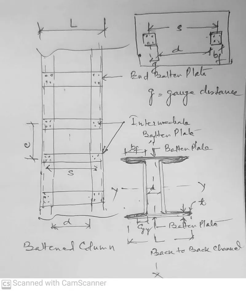
Q-5. Design of battened column
Design a battened column made up of two channels back to back of 5 m height to carry factored axial load of 2000kN. The Battens are welded. Design of weld not required. Use Hot rolled channel sections.
Aim - Design of battened column made up of two channels back to back
Introduction ( Given & assumed data):
- Height of column = 5 m
- Battens are welded
- Assuming steel Grade Fe 410 so `F_u`=410 N/`mm^2` and `f_y`=250 N/`mm^2`
- Effective slenderness ratio shall be 10% more than individual column to take care of shear deformation due to unbalance horizontal force as per IS 800:2007, CL7,7,14
- Assuming End condition hinged-hinged so K=1
Procedure (Solution)-
1) Assuming `f_cd`=175 N/`mm^2`
2) Area required A=`P_u//f_cd`= 2000x`10^3`/175 =11428.571 `mm^2`=114.28571 `Cm^2`
3) Choosing ISMC 400 @ 49.4 Kg/m with gross area 64.93 `Cm^2` of one channel.
Specification of channel- `I_XX`=15082 `Cm^2`, `I_YY`=504.8 `Cm^2`
Effective area of two channel `A_e`= 125.86 `Cm^2` , `r_x x`=15.48 Cm , `r_YY`=2.83 Cm
`C_yy`=2.42 Cm , g= 60 mm
4) Buckling class- For any built up section buckling class ' C class'
5) Slenderness Rato `lambda`= 1.1xKL/r =1.1x 5000/154.8 =35.5
6) Calculating `f_cd`for `lambda`=35.5 for buckling class C fro mtable 9C at page 42 of IS 800:2007
`lambda` `f_cd`
30 211
35.5 ?
40 198
`f_cd` = 211- (35.5-30)(211-198)/(40-30) = 203.85 N/`mm^2`
7) Design compressive strength `P_d`= `A_exx f_cd`
= 12586x 203.85 = 25656656.1 N
= 2565.66 KN> 2000 KN ( Hence safe)
Design of Batten Plates
1) Spacing of back to back channel- ( Using parallel axis theorem)
`I_XX= I_YY` 2x`I_XX`= 2x`I_YY`+A`(C_yy+d//2)^2`
2x15082x`10^4`= 2{504.88x`10^4`+6293`(24.2//2+d)^2`
d=140.1 mm , Provide d= 160 mm
2) Vertical Spacing between the Batten plates (C)
C < 0.7x`lambda`x`R_yy` & C < 50x`R_yy`( C should be lesser of two condition)
C= 0.7x35.5x28.3 =703.25 mm ; C= 50x28.3= 1415 mm
Select C = 700 mm
3) Size of End batten (`(d_e)`
Effective depth of end batten `(d_e')`= d+ 2`C_yy` > 2x`b_f`
= 160+ 2x24.2 > 2 x 100
208.4> 200 ( OK)
Over all depth of end batten `d_e`= `d_e'`+ 2e 208.4+2x35= 278.4 mm ,
Provide `d_e`= 290 mm ( Where e= end distance which is 35 welded connection)
4) Size of Intermediate batten ( `d_i`)
Effective depth of intermediate batten`d_i'` =(3/4)x`d_e'` = 0.75x208.4 =156.3 mm
Over all depth of intermediate batten `d_i`= d_i' +2e = 156.3 +2x35 =226.3 mm
Provide `d_i`= 240 m`
5) Thickness of batten plates (t)
t= (d+2g)/50 = (160+2x60)/50 = 5.6 mm ( where g is gauge distance)
Provide t= 8 mm
6) Length of batten (L)
L= d+ 2`b_f` = 160+2x100 = 360 mm ( where `b_f` is width of flange)
Provide L= 360 MM
Provide End batten 360x 290x8
Provide Intermediate batten 360x 240x8
7) Forces on the batten-
Transverse shear `V_t`=2.5% of bdesign load on column = (2.5/100)x2000= 50 KN
Longitudinal shear `(V_b)` = `V_t`xC/NS ( where S = d+2g = 160+2x60 = 280 mm)
( Number of battening system, here N=2)
= 50x`10^3`x 700/2x280 = 62500 N = 62.5 KN
Bending moment (M)= `V_txxC//2xxN` = 50x 700x`10^-3`/2x2 = 8.75 KN-m
8) Checks for stresses in batten-
We shall check for only intermediate batten. If design is safe for intermediate batten ,it will be safe for end batten also as its size is larger than intermediate batten
Shear stress in Intermediate batten = `V_b//d_ixxt < f_y//sqrt3xxgamma_mo`
= 62.5x `10^3`/ (240x8) < 250/(1.732x1.1)
32.55 < 131.21 ( OK), hence safe in shear stress
Bending stress in Intermediate batten = 6M/tx`d_i^2` < `f_y//gamma_mo`
= 6x8.75x`10^6`/(8x `240^2`) < 250/1.1
= 113.93 < 227.27 (OK), hence safe in bending stress
Result : From the above it is concluded that built up column 2 ISMC placed back to back are safe in taking factored load. Further Batten plate are safe to resist shear stress and bending stress.
Q-3. Design circular tube strut member for certain load
Design 2 m long tubular strut member to carry factored axial load of 400 kN. Assume the ends of the member are simply supported and the yield strength fy=210 Mpa. Also find Equivalent Square hollow sections.
Aim:- Design of Tubular strut and finding out equivalent square hollow section
Introduction ( Given & assumed data):
- Factored/Design axial Load `P_u`= 400KN
- Member is simply supported
- Length of strut = 2 m
- Assume grade of steel YSt 240
- Permissible axial stress in compression `F_c`= 1500 Kg/`Cm^2`
Procedure ( Solution) -
1) `F_c`=1500Kg/`Cm^2`=1500 x9.8/100 =147 N/`mm^2`
2) Area required A = `P_u//F_c` 400x`10^3`/147 =2721.088 `mm^2`
3) Choosing tubular section of nominal bore 200 mm light class with following properties-
From table-1 at page-3 of IS 1161: 1998
`A_e`= 32.3 `Cm^2` , Wt = 25.4 Kg/m , Thickness = 4.8 mm , I =1856.51`mm^4` ,
r= 7.58 cm , Z=169.47 `Cm^2`
4) Slenderness ratio `lambda`= KL/r , here K= 0.85 for strut member
= 0.85x 2000/75.8 = 22.42 < 80 (safe in `lambda`)
5) Permissible axial stress in compression for `lambda`= 22.42 for YSt 240 grade of steel
from table-2 at page-6 of IS 806 :1968 ( By Interpolation)
`lambda` `F_e (Kg//Cm^2)`
20 1400
22.42 ?
30 1352
`F_t` = 1400- { (1400-1352)(22.42-20)/(30-20)} =1388.38 Kg/`Cm^2`
`F_t`= 1388.38 x9.8/100 = 136 M/`mm^2`
6) Design compressive strength of member `P_d`= `A_exx F_t`
= 32.3x100x 136 =439280 N
= 439 KN > 400 KN (Safe)
Finding Euivalent square Hollow Section -
Choosing square hollow section of dimension 180 x180 x6 from IS 4923,Table-1 ammendment-2 at page-1 issued in 2 May 2005h with following specification-
A= 40.83 Sq Cm , I= 2036`cm^4` , Wt= 32.05 Kg/m , r = 7.06 cm ,
Result :- It is concluded that tubular section of nominal bore of 200 mm light class is adequate for compressive factored force of 400 KN and also safe in buckling. Square hollow section of dimension 180 x180 x6 is nearly equivalent of designed tubular section
Q-2. Design Axial strength determination of a column with its end conditions
Calculate the Axial compressive capacity of Column made up of Hot rolled ISMB 300 with flange cover plate of 200x12 mm on each flange having length of beam as 3 m. Assume the bottom of the column is Fixed and Top as Roller (Rotation Fixed, translation free). Yield strength of material fy= 250 N/mm2
Tip Steps:
- Determine new radius of gyration of compound section
- Using Buckling curve classification & slenderness ratio using table 9c in code, calculate compressive strength
- Using compressive strength, calculate design strength multiplying the cross sectional area.
Aim- To find Axial Compressive strength of column
Introduction ( Given & assumed data)-
- Column is hot rolled ISMB 300 with flange cover plate of 200x12 mm
- Length of Column= 3 m
- End condition- one end fixed other is roller support ( Effective length factor K=1.2)
- `f_y`=250N/`mm^2`
Procedure ( Solution)
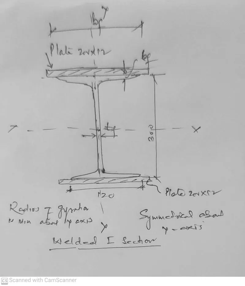
1) Calculation of radius of gyration-
Section properties of ISMB 300:
A = 56.26 `Cm^2`, `I_XX` =8603.6 `Cm^4` `I_YY`= 453.9 `Cm^4` , `r_XX`= 12.37 Cm
`r_YY`= 2.84 Cm , h= 300 mm , `t_f`=12.4 mm , `t_w`=7.5 mm , `b_f`=140 mm
Min radius of gyration will be about Y axis so Iyy of welded/built up section is requred
MI of Built up/welded section Iyy' = MI of Rolled section Iyy +2x ML of one plate
= 453.9x`10^4`+ 2x12x`200^3`/12 = 20539000 `mm^4`
`A_e`= Area of rolled section + 2x Area of one plate = 5626+ 2x200x12=10426 `mm^2`
`r_min` =`sqrt( I_min//A)` = `sqrt(2053.9xx10^4//10426`=`sqrt(1969.97`)= 44.38
`r_min`= 44.38
4) Slenderness ratio `lambda`= KL/`r_min` = 1.2x 3000/44.38 = 81.117 < 180
SAFE IN BUCKLING
3) Buckling class- The given section is welded I section so as per IS 800:2007 (TABLE 10, pg-44)
`t_f`=12.4 <40 so its buckling class 'C' (`lambda`is min for class 'C')
4) Calculation of `f_cd` for `lambda`=81.117 ( Using table 9C at pg 42 of IS 800 :2007)
`lambda` `f_cd`
80 136
81.117 ?
90 121
`f_cd` = 136- {(136-121)(81.117-80)/(90-80) = 134.32 N/`mm^2`
Compressive strength of column `P_d`= `A_exx f_cd`= 10426x134.32 =1400420.32 N
OR `P_d`= 1400.42 KN
- Result- It is concluded that the given welded I section with plates on bothe the flange has compressive strength of 1400 KN and safe in Buckling
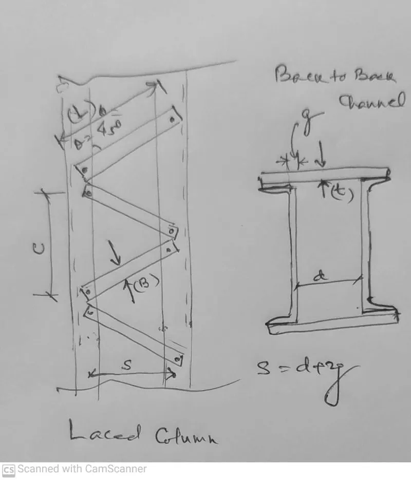
Q-4. Design of laced column
Design a single laced column made up of two channels back to back of 10 m height to carry factored axial load of 1000kN. The lacings are bolted. Design of bolted connection not required.
Aim:- Designing laced column
Introduction:
- Height of column = 10 m
- Factored Axial load on column `P_u` = 1000KN
- Assuming steel Grade Fe 410 so `F_u`=410 N/`mm^2` and `f_y`=250 N/`mm^2`
- Effective slenderness ratio shall be 5% more than individual column to take care of shear deformation due to unbalance horizontal force as per IS 800:2007, CL7,7,14
- Assuming End condition hinged-hinged so K=1
Procedure-
STEP-1 Assuming `f_cd`=130 N/`mm^2`
STEP-2 Area required (A) = `P_u//f_cd`= 1000xx10^3/130= 7692.30 `Cm^2`
STEP-3 Now choosing two ISMC 300 with follwing specification-
Effective area `A_e=`45.64 `Cm^2`x2 = 91.28 Cm`Cm^2`
`I_x x`=6362.6 `cm^4`= 6362.6x`10^4 mm^4`
`I_yy=`310.8`cm^4`= 310.8x`10^4 mm^4`
`r_x x`=11.81 cm = 118.1 mm , `c_yy`=2.36 cmm= 23. mm , g= 50 mm
STEP-4 Buckling claas : For any builtup section buckling class is "C Class"
STEP-5 Slenderness Rato `lambda`=KL/rx1.05 =1x 10000x1.05/118.1=88.9
STEP-6 For `lambda`calculating `f_cd` by interpolation using table 9C pg-42 of IS 800:2007
`lambda` `f_cd`
80 136
90 121
`f_cd` for `lambda`=136-{(136-121)/(90-80)}x(88.9.63-80) =122.65 `N//mm^2`
STEP-7 Design comprssive strength `P_d`=`A_etimes f_cd`= 9128x122.65=1119549 N
= 1119.54 KN>1000KN( Safe)
Design of Lacing bar-
1 ) Clear spacing of channel S=d+2g where d = spacing b/w two channel section and g= gauge distance
For calculating (d) `I_x x= I_yy`
2x6362.6 x`10^4` =2{ 310.8x`10^4`+4564(d/2 +23.6)`
d = 183.1 mm
S= 183.1 + 2x 50 = 283.1 m m
2) Assuming `theta`= 45 degree
3) `Vertical spacing (C)= 2S `tan theta`` 283.1 `tan45`= 283.1 mm
4) Length of lacing bar (L) = S/`Cos theta`= 283.1/`Cos45`= 400.36 mm
5) Thickness of Lacing bar ( T) = L/40 for single lacing = 400.36/40 =10.009
say t = 12 mm
6) Width of lacing bar (B) = 3X16 = 60 = 48 MM say B = 50 mm
Providinf 50 ISF 12
7) Area of lacing bar (A)= Bxt = 50x 12 = 600 `mm^2`
8) Radius of gyration (R)= `T//sqrt2`=3.46 mm
9) Slenderness ratio (`lambda`)= KL/R= 400.36/3.46= 115.71 < 145 ( OK)
10) Calculation of `f_cd` by inerpolation using table 9C at pg 42
`lambda` `f_cd`
110 94.6
120 83.7
`f_cd`= 94.6- (115.71-110)(96.6-83.1)/120-110 = 88.37 `N//mm^2`
11) Design compressive strength of lacing bar (`P_L) =A_etimes f_cd`
= 600x88.37 = 53022 N = 53.02 KN
V=`V_t//2` where `v_t`is 2.5% of total load(`P_d`)
V=Transverse shear resisted by lacing system
`V_t`= 2.5/100 x 1119.54 = 27.98 KN
V= `V_t//2` = 27.98/2= 13.99 say 14 KN HeeE `P_L`> V ( Safe)
Result : From the above it is concluded that built up column 2 ISMC placed back to back are safe in taking factored load. Further lacing bar 50 ISF 12 is also safe to resist transfer shear which is 2.5% of total load on column. Slenderness ratio of Lacing bar is also within the permissible limit of 145.