Project 1
1} AIM :-
Route the Wiring harness on Given Engine and Prepare flatten view drawing in CATIA V5. Application of all Packaging rules, Industry best practices studied in this course shall be demonstrated in design. Apply Protection coverings as required.
2} INTRODUCTION :-
The automotive wiring haness is referred to as the central nervous system in the vehicle. It mainly consists of an electrical harness and the mechanical harness in the design. The current project is focused on the mechanical wiring harness and its rules and procedure to be followed while routing in the virtual condition. CATIA V5 electrical workbench is used as the CAD tool for routing the wires in the engine and tailgate components.
Some terms need to be understood before designing the wiring harness.
A) Basics of the electrical distribution system and wiring harness
Electrical Distribution System (EDS): It deals with physical (location of electronic components placed in the vehicle, front end to back end) and logical (different Electrical Control Units) architecture, schematic development, power distribution (set with fuses to check wiring harness is safe in various failure modes), wiring harness design and wiring harness component design of given electrical system.
E & E Architecture: It is a high-level logical connectivity diagram representing the number of systems, sub-systems, and logical connections between them. It is also extended to show the CAN (control area network) network between different electronic controllers.
Logical schematics: It is detailed design of E&E architecture which is extended to show the logical connectivity between different components and controls of different systems and sub-systems.
Electrical schematics: It is detailed design of logical schematics, which describe the pin-to-pin connectivity, properties, fusion distribution, grounding distribution, wire properties (wire type, colour, gauge), interconnects, circuit properties (circuit numbers, connector designation numbers, control device number), specification of component (rating od diode, resistors) etc., This is the end design of electrical core design of system and used as primary input for harness development.
Wiring harness topology: It is strategy to divide the harness between different pieces to achieve the best manufacturability, serviceability and cost-effective design.
Ex: engine harness, door harness, tail gate harness.
Note: Wiring harness cannot be repaired. It is advised to replace the damaged wiring harness parts.
Wiring harness routing: It is the desired path of wiring harness into given vehicle environment by applying set of design rules and industry best practices.
Wiring harness packaging: deals with the fixing/mounting strategy of wiring harness routing to ensure the safe, reliable and durability of wiring harness by applying set of design rules and industry best practices.
Virtual environment: 3D representation of vehicle components.
Benefits: 1) Huge cost saving, 2) Fuse failure avoiding, 3) Easy to predict i.e., warning in harness
B) Wiring Harness Terms
Wiring harness is the assembly of different systems, sub-systems in the vehicle. It won’t have any function; it depends on its system and sub-systems. It used to pass the signals between components.
Wires: Wiring harness consists of various wires bundled together, with each individual wire responsible for carrying electric signals and energy used ins tarting the engine, lights, meters, navigation system, Power windows and doors, and other devices in the vehicle. Wires are Cu conductors insulated with PVC insulation. Initiative in the industry to use the Al wire to get the benefits of weight and cost reduction.
Connector: An electrical connector, is an electro-mechanical device used to join Electrical termination and create an electric circuit. Electrical connectors consist of Housing, Terminal, Wedge Locks, Seals, Cavity, Mounting Cam etc., Connectors are plastic moulded housing with locking and retention features.
Terminals: Terminals are defined as “A device designed to terminate a conductor that is to be affixed to a post, stud, chassis, another tongue, etc., to establish an electrical connection.” Terminals are metal (brass) conductor with plating (tin, silver, gold) constructed in specific shape to secure the joint from environmental conditions and with minimum electrical resistance.
Protection device:
- Corrugated flexible tubes also known as Cot Tubes / Convoluted Conduits have a wide range of application in automotive industries.
- Corrugated tubes are made from plastic material and they are flexible.
- Theses tubes are used to protect the harness from thermal and physical damage, sometimes to improve harness appearance.
- Protection covering are flexible, temperature, wear and tear resistant moulded plastic/polymer parts.
- Sealing Grommets are used mainly for three purposes. Sealing, Protection and to absorb vibration/shock.
- Protection Grommets are rubber moulded components used in wiring harness for protections.
- Insulations are adhesive/non-adhesive tapes and sleeves. They are made from PVC or cotton/polymer material. Cotton tape in high temperature area (engine).
Clips and clamps: Wide variety of clips and clamps are available to mount the wiring harness.
Fuse and relay box: are plastic moulded parts used to package Fuses and relays in systematic manner. It also protects them for any damage (Physical and Environmental).
Retention device: are plastic moulded parts to mount connectors and other harness components. (Connector mounts, secondary locks, connector back shell etc). Primary locking is provided by the terminal itself; secondary locks are not mandatory but there are used to ensure that there is no damage. Back shells are the packaging devices which are used at the end of the connectors. It guides the wire to the connector in a constrain packaging area or to provide the better appearance at the end of the connector.
Guiding channels: are plastic moulded or metal parts designed to guide harness bundle in given geometric area to secure and protect the harness.
Electronic components: Diodes, terminating resistors, Flasher, Timer circuits are sometimes part of harness supply.
C) Typical design flow of EDS system
Logical Architecture, Electrical Schematics and Physical Architecture are designed by the electrical department whereas harness Routing and packaging is developed by mechanical department. Upon integration of electrical and mechanical departments final harness drawing is designed.
D) Wiring Harness Design Process
3} ENGINE WIRING HARNESS:-
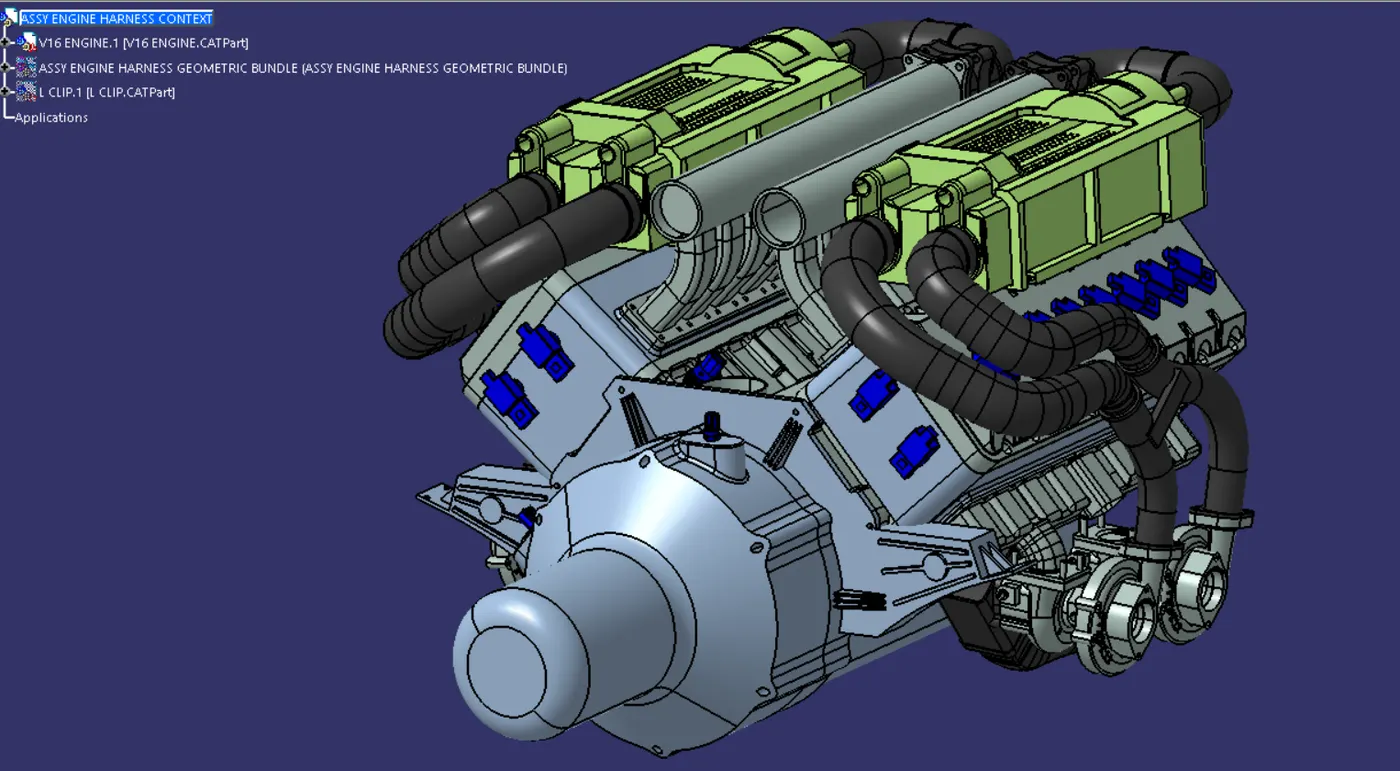
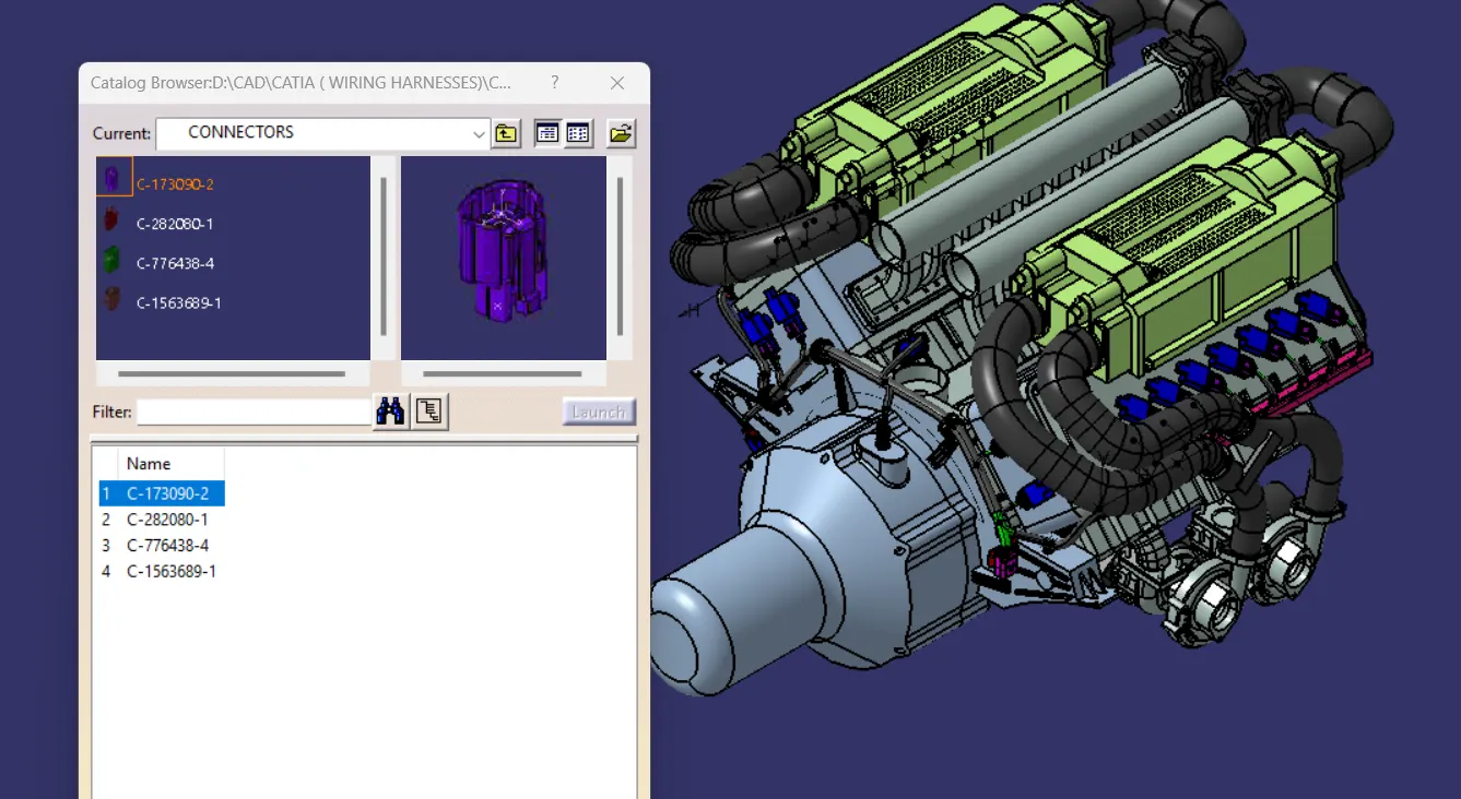
THE ABOVE FIGURE SHOWS THE GIVEN V16 ENGINE CAD DATA. HERE ROUTING THE WIRING HARNESS FOR THR FOLLOWING ELECTRICAL COMPONENTS ATTACHED TO THE ENGINE.
FUEL INJECTOR FOR EACH CYLINDER HERE, WE HAVE 16 CYLINDER ENGINE.
CAMSHAFT SENSORS ON EACH ENGINE BLOCK (4 CAMSHAFT SENSOR)
ENGINE COOLENT SENSOR AT THE CENTRE OF THE ENGINE BETWEEN THE TWO BLOCKS.
ENGINE OIL TEMPERATURE AND OIL PRESSURE SENSOR FITTED AT THE OIL SUMP OF THE ENGINE ON BOTH ENGINE CYLINDER BLOCKS.
SENSORS FOR SENSE NEUTRAL POSITION OF THE TRANSMISSION ASSEMBLY AND MEASUREMENT OF VEHICLE SPEED.
INTERCONNECTION CONNECTOR TO CONNECT ENGINE HARNESS SYSTEM TO VEHICLE HARNESS SYSTEM.
HARNESS MOUNTING AND ROUTING MANAGEMENT REQUIRWD TO PROVIDE PROPER PACKAGING OF WIRING HARNESS. IT ALSO DEALS WITH CLEARENCE MANAGEMENT AND MANUFACTURABILITY.
P-CLAMPS TO PROVIDE POSITIVE CLAMPING AND PROPER CLEARENCE MANAGEMENT FOR THE ROUTING.
MOUNTING CLIPS FOR THE CONNECTOR MOUNTING.
GUIDING CHANNELS PROVIDE THERMAL PROTECTION IN HIGH TEMPERATURE ZONES.
CORRUGATED TUBES USED TO PROTECT THE WIRING HARNESS FROM HAZARDOUS LIQUIDS AND TEMPERATURE.
4} DESIGN METHODOLOGY :-
1. DOWNLOAD THE 3D CAD DATA OF ALL THE REQUIRED CONNECTORS AND MOUNTINGS FROM THE SITE www.te.com .
2. DEFINE ALL THE CONNECTORS AND MOUNTINGS CLIPS ELECTRICALLY BY DEFINING ALL OF ITS PROPERTIES.
3. ADDING ALL THE CONNECTORS TO CATLOGUE DOCUMENT.
4. CREATE NEW PRODUCT FILE IN THE ASSEMBLY WORKBENCH NAMED AS ASSEMBLY WIRING HARNESS CONTEXT , USING TOP DOWN APPROACH THIS WILL BE TOP LEVEL OF PRODUCT FILE INSIDE THIS PRODUCT FILE CREATE GEOMETRICAL BUNDLE FOR ALL THE CONNECTORS AND WIRE HARNESS ELECTRICAL BUNDLE , V16 ENGINE , L SHAPE BRACKET.
5. ORIENTATION OF ALL THE CONNECTORS , CLIPS , GUIDING CHANNEL'S , L SHAPE BRACKET AT APPROPRIATE LOCATIONS.
6. ROUTING THE HARNESS THROUGH ENGINE , BUNDLE CONNECTIVITY CHECK .
7. USE OF COT-TUBES FOR BEST INSULATION AND PACKAGING , FLATTENING AND DRAWING CREATION.
5} PROCEDURE :-
Open the cad data of connectors in catia part design workbench and create the connector connection point,connector connection axis system , bundle connection point .Then Switch to electrical part design workbench and define it as a connector also define connector connection point and bundle connection point.
Here we have inter connection connector it require mounting clip for mounting the connector .so cavity connection point should be defined for this connector. .
(A) CREATE MID POINT IN BETWEEN THE TWO POINTS OF CONTACT FACE WHICH WILL BE NORMAL TO THE WIRE BUNDLE INSERTION :-
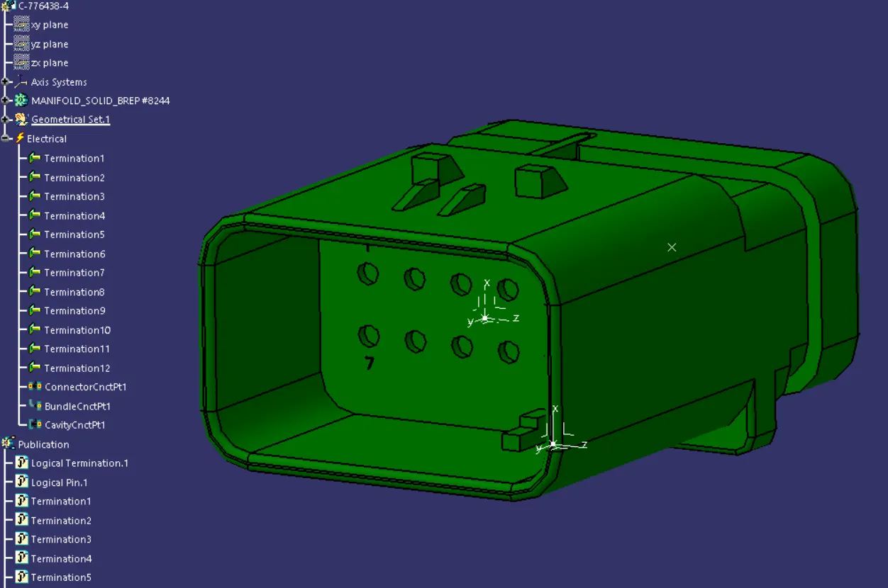
(B) CREATE AXIS SYSTEM WITH RESPECT TO THE POINT CREATED AND DEFINE THE Y AXIS OF AXIS SYSTEM POINTING TOWARDS THE FRONT FACE OF THE CONNECTOR , Z AXIS SHOULD BE POINTING ACROSS THE CONNECTOR FROM LEFT TO RIGHT , X AXIS SHOULD BE POINTING IN THE DIRECTION TOWARDS THE LOCKING MECHANISM OF THE CLIP.
(C) BUNDLE CONNECTION POINT :-
CREATE MID POINT ON THE BACK FACE USING THE MIDDLE CIRCLE OF THE CONNECTOR WHICH WILL BE NORMAL TO THE BUNDLE INSERTION.
(D) CREATE CAVITY CONNECTION POINT ON THE MIDDLE POINT OF THE CURVE OR LINE LAYING ON THE CONTACT FACE OF THE CONNECTOR TO THE CAVITY.
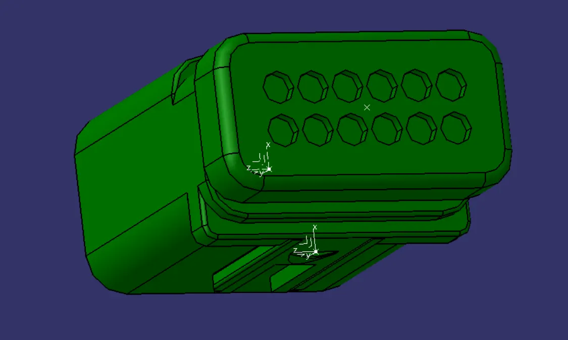
(E) CREATE CAVITY CONNECTION AXIS SYSTEM.
(F) SWITCH TO ELECTRICAL PART DESIGN.
DEFINE THE PART AS A CONNECTOR IN CATIA , THEN PROVIDE NO. OF TERMINATIONS AS 12 , BECAUSE THIS CONNECTOR CONSIST OF 12 ENTRY POINTS FOR WIRE.
(G) DEFINE BUNDLE CONNECTION POINT.
(H) DEFINE CONNECTOR CONNECTION POINT.
(I) DEFINE CAVITY CONNECTION POINT.
FOLLOW SAME PROCEDURE FOR ALL OTHER CONNECTORS TO DEFINE ALL ELECTRICAL PARAMETERS TO THE CONNECTORS:-
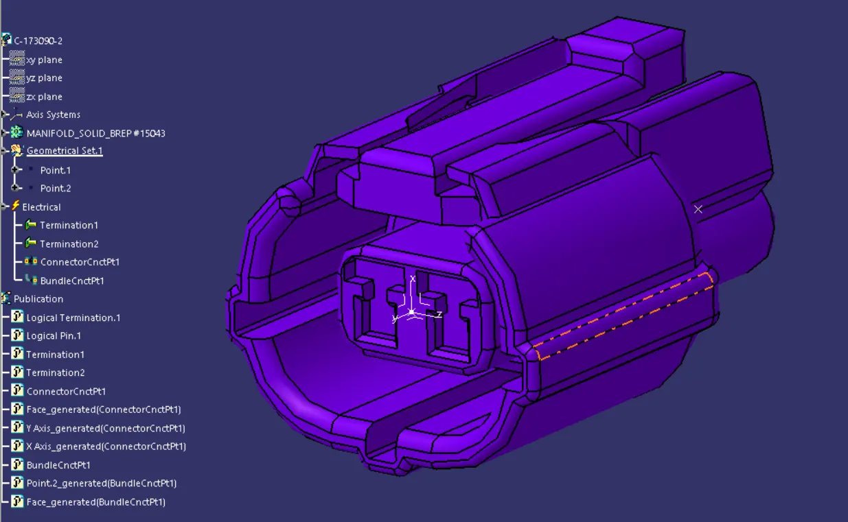
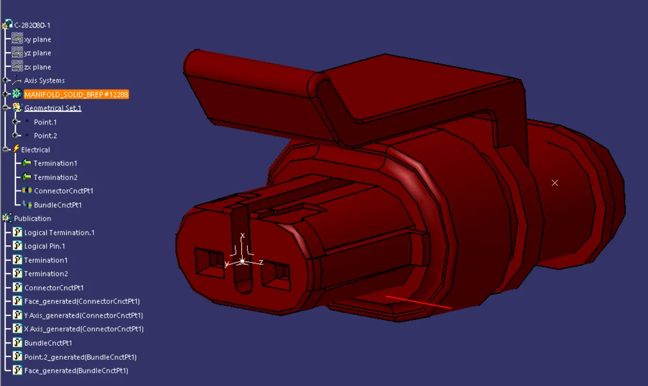
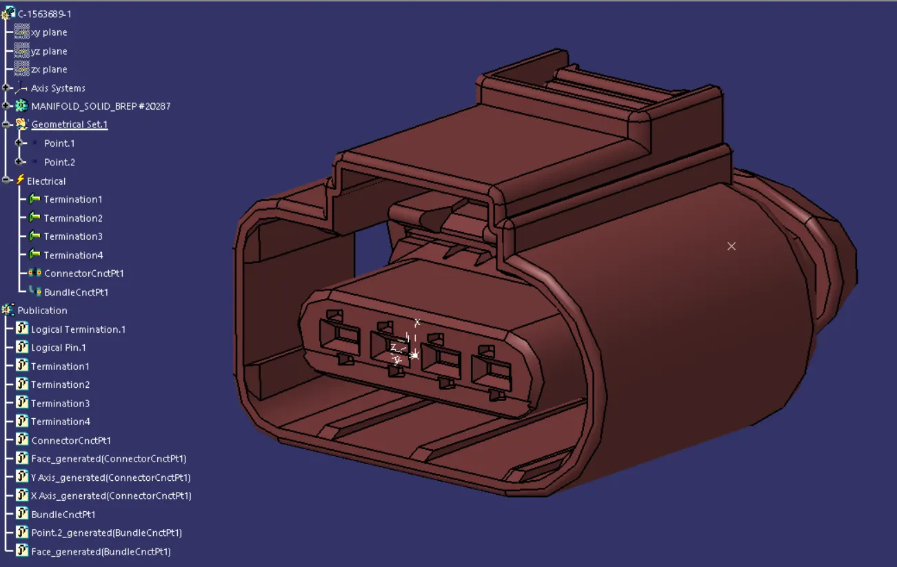
Download the other harness mountings like clips and clamps cad data.Also download the brackets for parking the interconnection connector and channel for routing the harness in high temperature zones
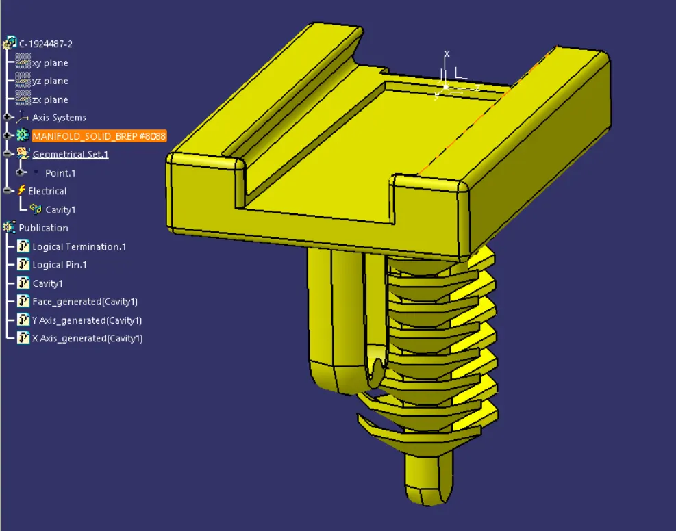
MOUNTING CLIP :-
- Define the mounting clip electrically by defining all the properties .
Define the clip as mounting equipment using mounting equipment command. Select cavity command and define the parameters.
- A) CREATE MID POINT USING THE UPPER LINE LAYING ON THE CONTACT SURFACE OF THE CAVITY.
- B) CREATE CAVITY CONNECTION POINT.
- C) CREATE CAVITY CONNECTION AXIS SYSTEM AND ORIENT THE CAVITY CLIP AS THE SAME WAY AS CONNECTOR.
- D) SWITCH TO ELECTRIC PART DESIGN AND DEFINE THE PART AS MOUNTING EQUIPMENT.
- E) DEFINE CAVITY CONNECTION POINT.
ELECTRICAL ASSEMBLY DESIGN :-
(A) CREATE ASSEMBLY IN ELECTRICAL ASSEMBLY DESIGN COPY BOTH THE CONNECTOR AND THE CAVITY CLIP PASTE IT TO THE ELECTRICAL ASSEMBLY.
(B) SELECT DEFINING ELECTRIC CONNECTION, USE CONNECT ELECTRICAL DEVICES COMMAND.
(C) SELECT CAVITY AND CONNECTOR.
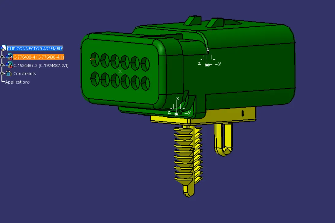
All the connectors defined as electrical connector and defined all the necessary properties to Connectors.Created a catalog document in connector family and stored all the connector data in catalog document .
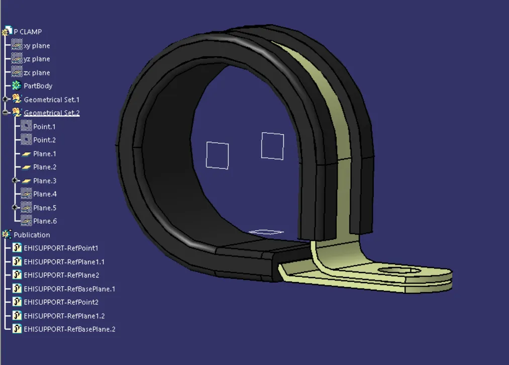
P-CLAMP:-
A) CREATE TWO POINTS AT THE CENTRE OF THE ENTRY AND EXIT OF THE CLIP BY SELECTING POINT TYPE AS RADIUS OF CIRCLE.
B) CREATE PLANES AT THE ENTRY AND EXIT POINTS OF THE CLIP AND ANOTHER PLANE AT THE BASE FOR RESTING OF THE BUNDLE WHICH IS OFFSETED AT DISTANCE OF 2 MM FROM THE BASE .
C) SWITCH TO ELECTRIC PART DESIGN.
D) CLICK ON SUPPORT DEFINATION SELECT THE P CLAMP PART THEN , SELECT THE ENTRY POINT AND PLANE THEN, SELECT THE EXIT PLANE AND BASE PLANE.
E) AGAIN CLIK ON SUPPORT DEFINATION THEN, SELECT THE P CLAMP PART , THEN SELECT EXIT POINT,PLANE AND THE BASE PLANE AS SECONDAY PLANE IS TAKEN BY DEFAULT.
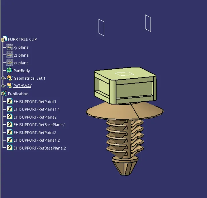
FURR TREE CLIP:-
A) First define geometrical parameters such as entry point, entry plane, exit point, exit plane and base plane .
B) Then switch to electrical part design workbench and define the fur-tree clip as support using support command and define the parameters.
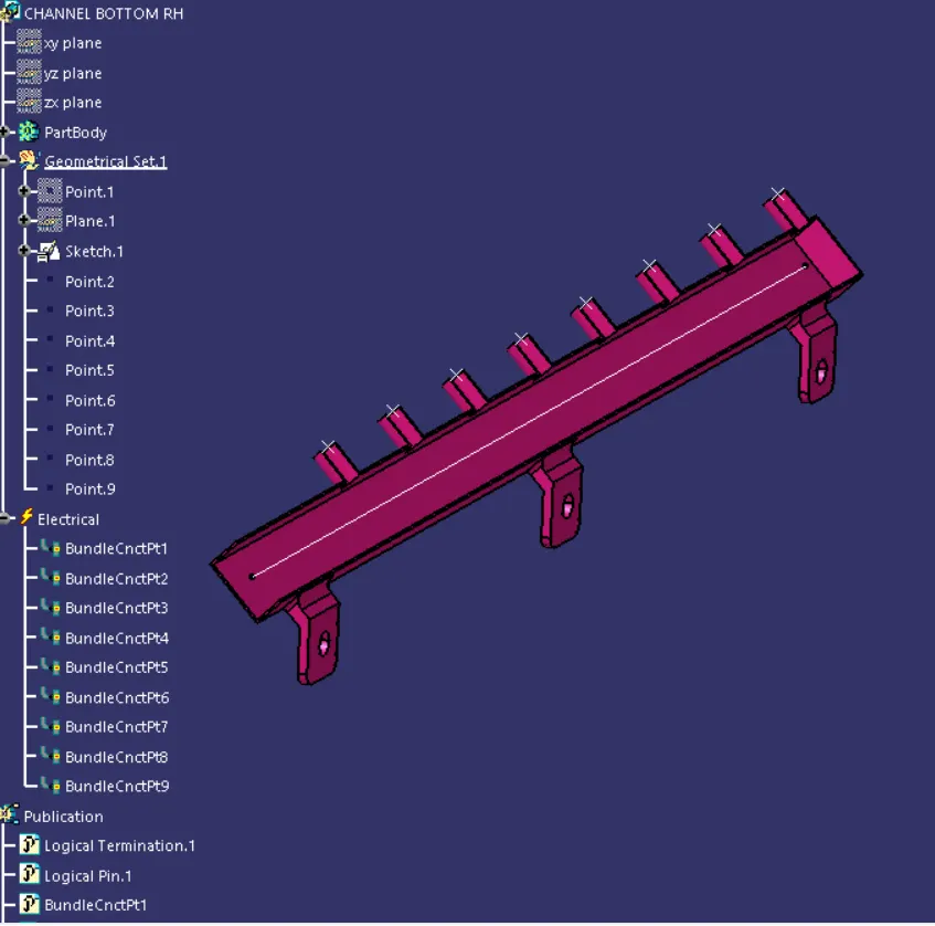
PLASTIC GUIDING CHANNELS :-
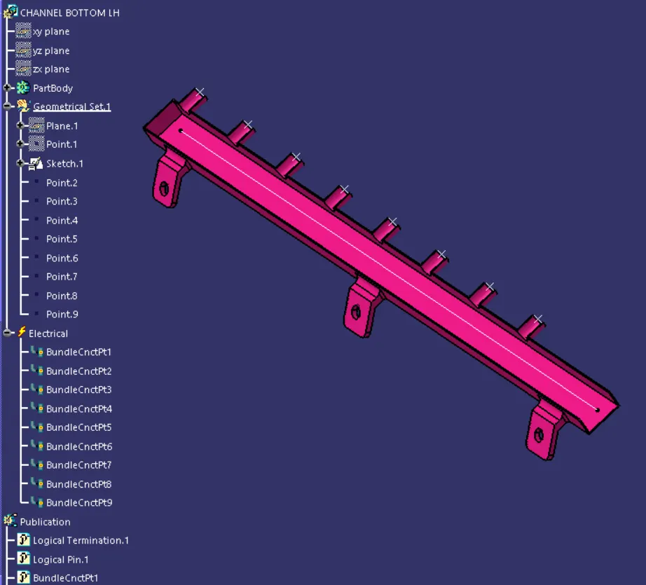
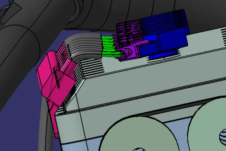
The given V-16 engine has 8 injectors both on the left and right side of the engine which are close to one another, so plastic guiding channel is used for trouble free routing of the wiring harness in addition it provide thermal protection from high temperature zones of the engine.
First create geometrical parameters such as bundle entry points, and external reference line in the part design workbench to route the wiring harness into the guiding channel trhen define the guiding channel as a electrical part by using the define equipment option .define all the properties to the channel .
SHEETMETAL BRACKET :-
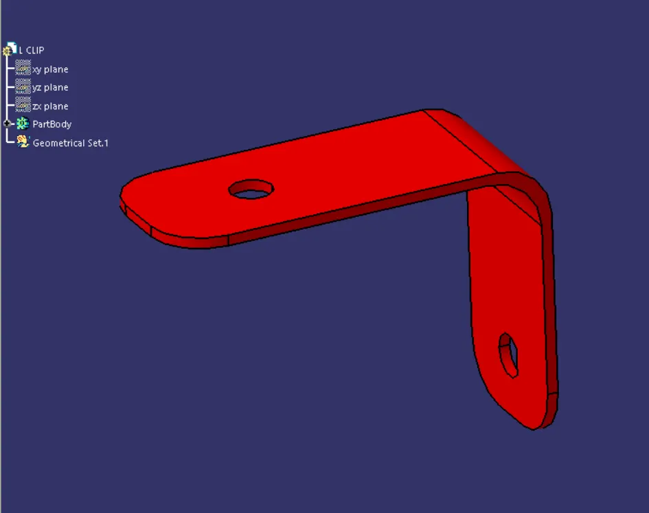
Add sheet metal bracket in order to provide parking for the interconnection connector. Also, we have to make sure that the bracket is placed inside the context assembly and outside of engine and geometrical bundle assembly.
Add all the electrically defined components to the geometrical bundle.place the components at proper location for routing the harness
- Then switch into the electrical harness assembly workbench and Geometrical bundle product file should be electrically defined using the Define Geometrical bundle option .
6} HARNESS ROUTING AND PACKAGING :-
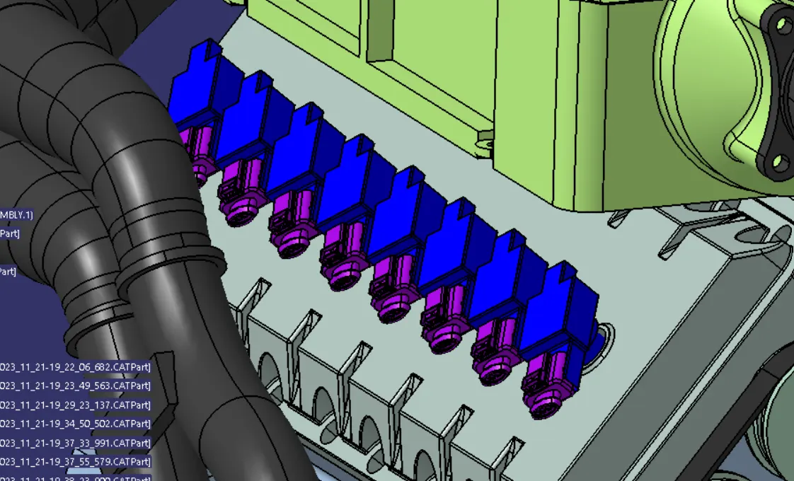
- The available connectors are added into the geometrical bundle and properly positioned onto the fuel injectors, camshaft sensors, vehicle speed sensor, neutral position sensor and engine coolant sensor.manipulation tool is used to place the connectors.
- Here we have one interconnection connector to connect engine harness system to vehicle harness system.so it required additional parking provision.Existing bolt on the engine is used to mount the sheet metal bracket. The bracket should be provided with a suitable locking feature in clockwise direction.first mount the clip on the sheet metal bracket .Then the interconnection connector is electrically connected with the mounting clip by using connect electrical devices command in the electrical assembly design workbench.
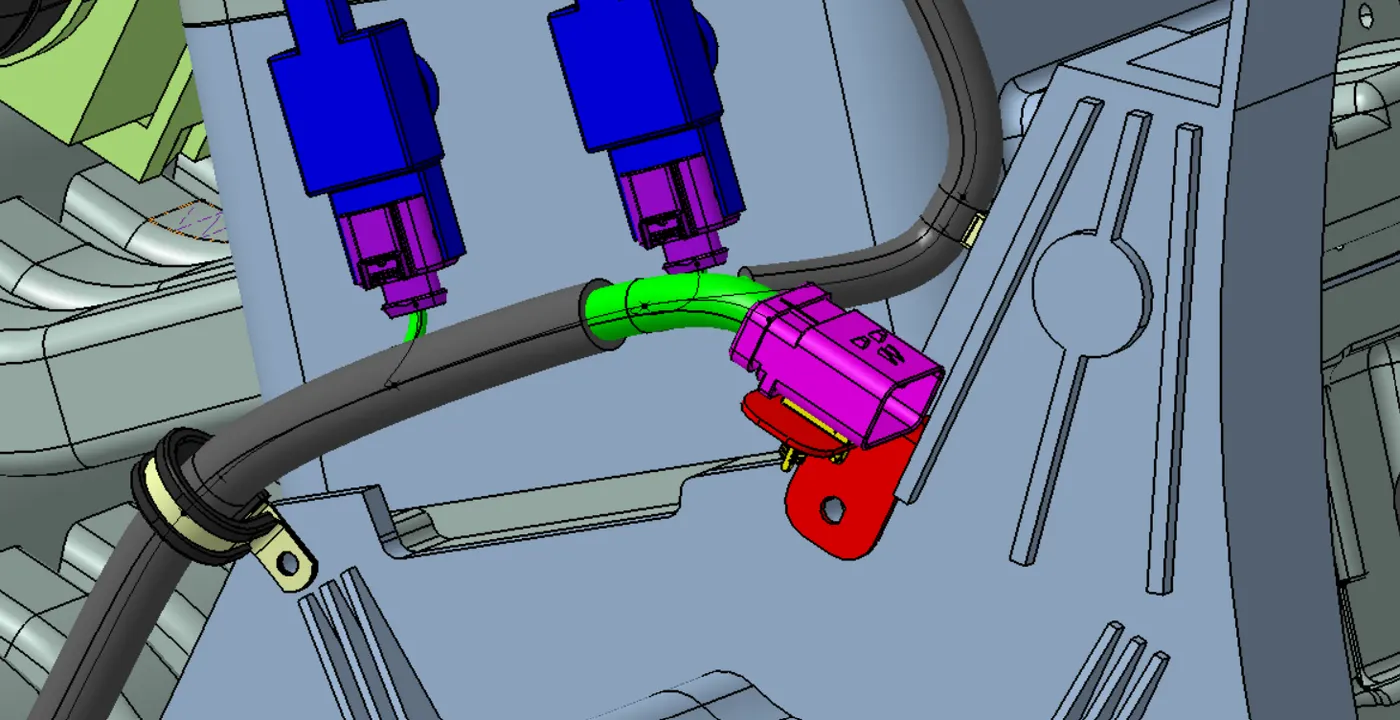
Properly parked the electrically connected interconnection connector and mounting clip on the sheetmetal bracket
Adding supporting components like p-clamps and fir-tree clip . P-Clamps are mounted on the existing bolts and screws to provide positive clamping and ensure proper clearance management for the wiring harness routing and also help to prevent the harness fouling from unwanted mechanical components.
- P - Clamp and the Fir Tree can be placed at appropriate location and ensure clearance management.
- The p – Clamps can be mounted to the existing holes provided on the Engine block in which the screws to tighten the Engine block.
- After finalization of the routing, request the Engine design team to provide the threaded holes for fix the Fir tree clips as per their location.
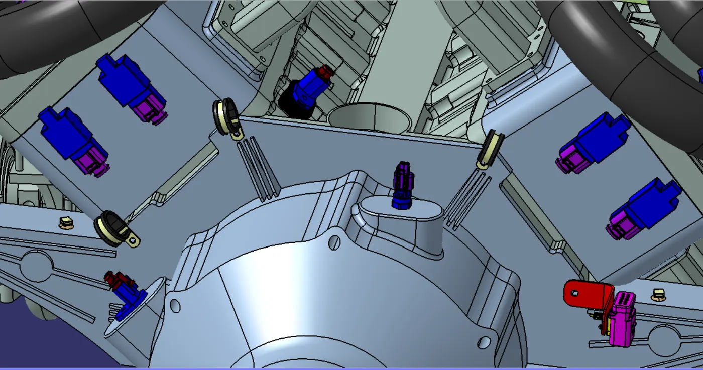
- Add guiding channel for routing the wiring harness to the fuel injectors.it deals with clearance management and thermal protection of the wiring harness in the high temperature zones.Then request engine design team to provide additional threaded holes required to mount the guiding channels in proper location by using bolts or screws .
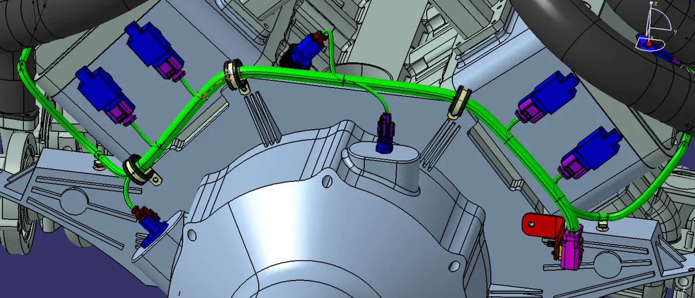
After define the geometrical bundlel electrically, Then select the multibranchable command to start the bundle routing and click on the route definition.
The bundle routing starts from interconnection connector and then to the P-clamps and to the guiding channels. Adding branche points to route the wiring harness from main branch to various connectors.
To route the wiring harness through the guiding channels select external curve option and click on the line created in the guiding channel.then add branch points to route the wiring herness from the guiding channel to the connectors .proper bend radius and slack provided for the bundle segment to avoid stress on the wire.
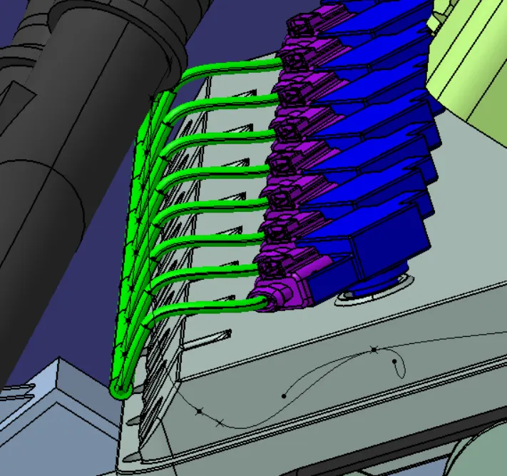
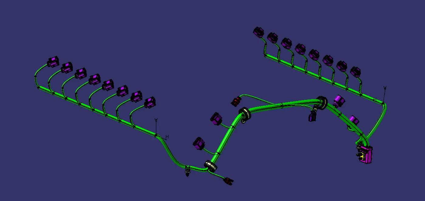
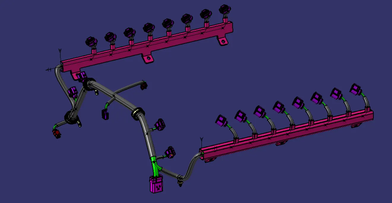 Add protective coverings on the wiring harness to protect wiring from high temperature . protective covering created by using define protection part command in the electrical part design workbench. Select part , and define the parameters as per the requirement.
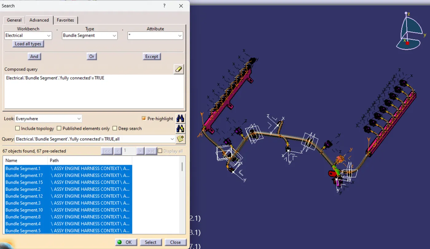
- The created corrugated tube can be added into the catalog by store device command and selecting the catalog file created for protective covering. then appropriate protective covering added to the bundle segments. After routing the harness then check the bundle Continuity .
Edit⮕Search⮕Advanced⮕Electrical Workbench⮕Type:-Bundle Segment⮕Attribute:-Fully Connected.Selecting the "TRUE" option in the attribute criterion it will show all the connected bundle segment.
DESIGN CRITERIA FOLLOWED TO ROUTE WIRING HARNESS :-
- Wiring harness routed by considering the factors ease in manufacturing, accessibility, easy removal and easy maintenance of attached equipments and routing harness.
- Wiring harness should be routed in such a way that it is easy to assemble on a vehicle.
- Wiring harness should be kept away from sharp environments like sheet metal brackets, panel edges, corners etc.
- Avoid harness routing and clipping in blind zone of operator during harness during installation.
- Ensure that routing meets the clearance requirements with the different surrounding parts.
- Routing shall provide enough slack for each branch to avoid additional stress on wire and terminal crimping joints but ensure that extra slack does not cause wiring harness foul with surrounding parts and impact desired clearance requirements.
- Enough clamps should be provided to ensure the positive clearance with surrounding and safety of wiring harness.
- Use of plastic guided channels are recommended to meet the clearances in critical areas if it is difficult to achieve by use of clamps.
- Branch length should be minimum 50mm.
- Minimum distance between clip and nearest branching point should be 25mm.
- Minimum distance between two breakouts should be 50mm.
- Limit the no. of branches from single branch point upto 4.
- Ensure that harness protection is provided according to surrounding temperature, manufacturabilty and expected reliability.
- The min. bend radius is to be 1.4.
- 7} WIRING HARNESS FLATTENING :-
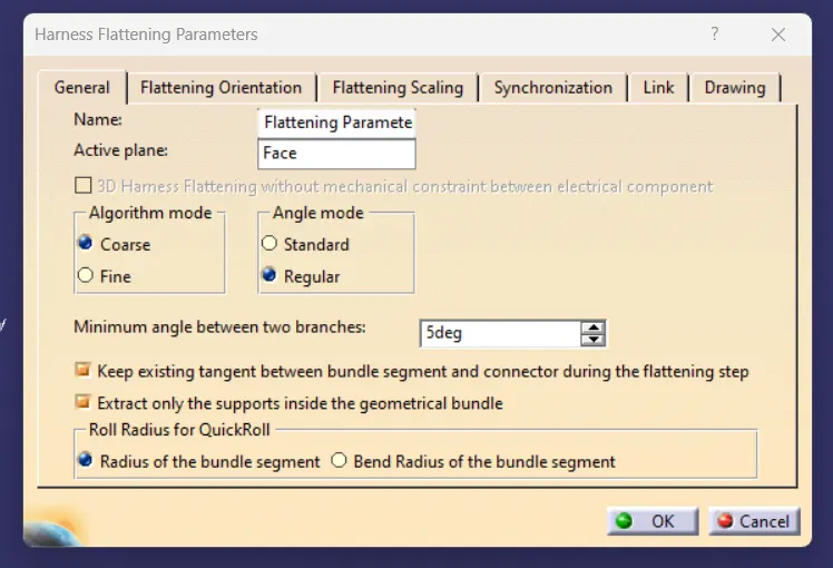
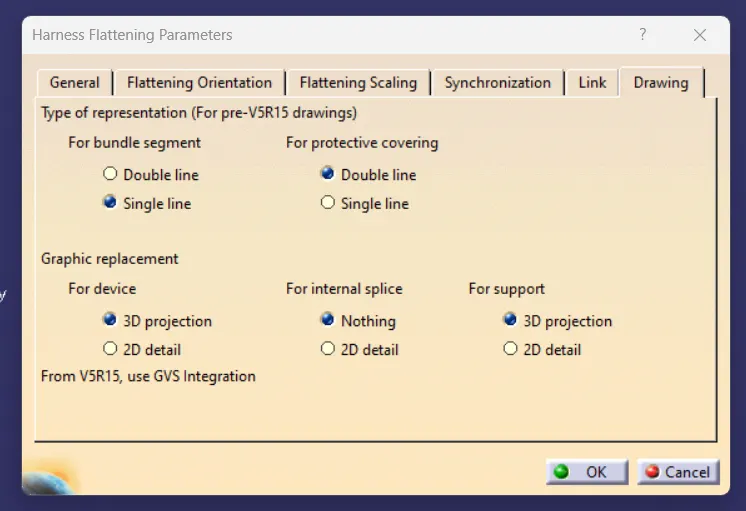
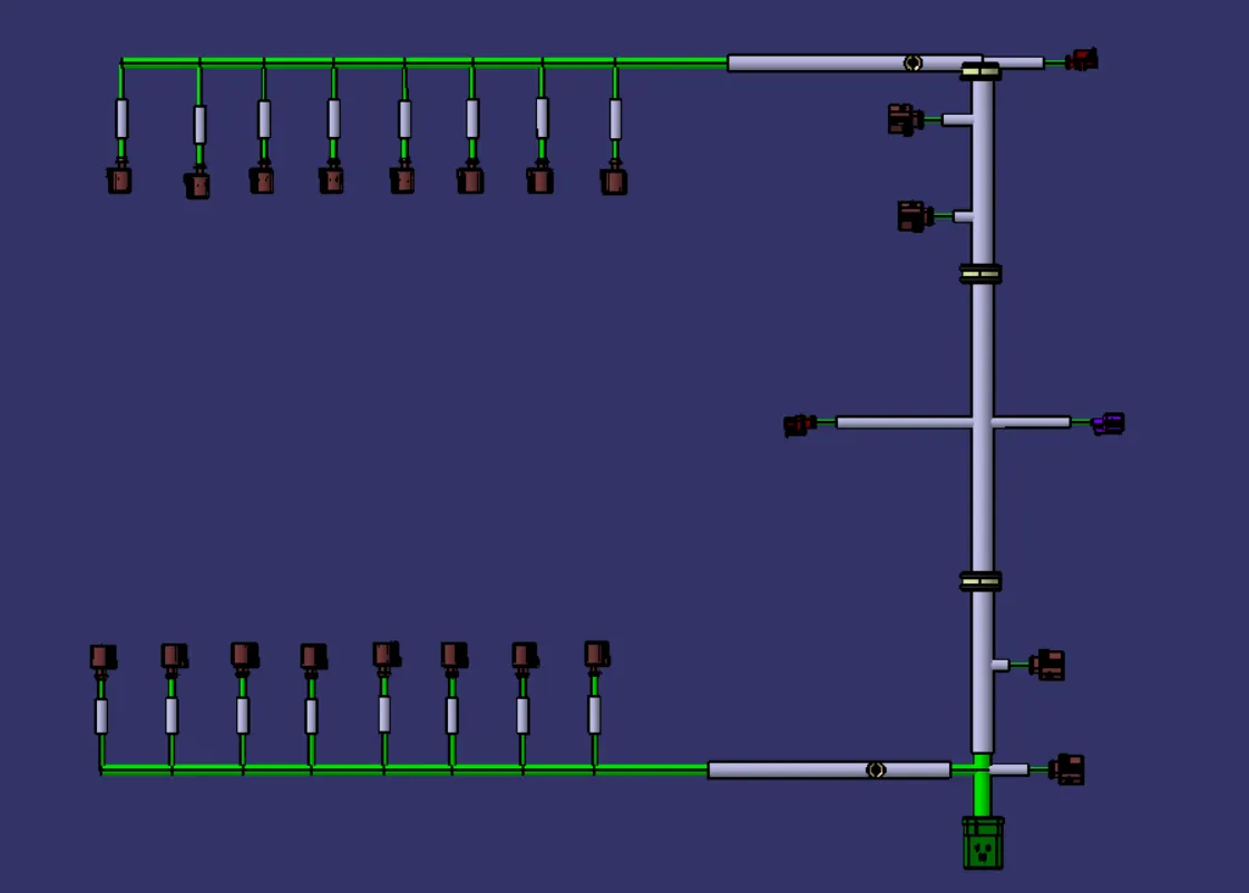
Create a new product file for flatten the wiring harness and save as in the same folder where the wiring harness is saved. Then switch to Electrical harness flattening workbench and select harness flattening parameters and define harness flattening parameters. Before creating flatten view, Make sure that selecting 'Double line' for bundle segment and 'Double' line for protective covering.
8} DRAWING OF THE FLATTEN WIRING HARNESS :-
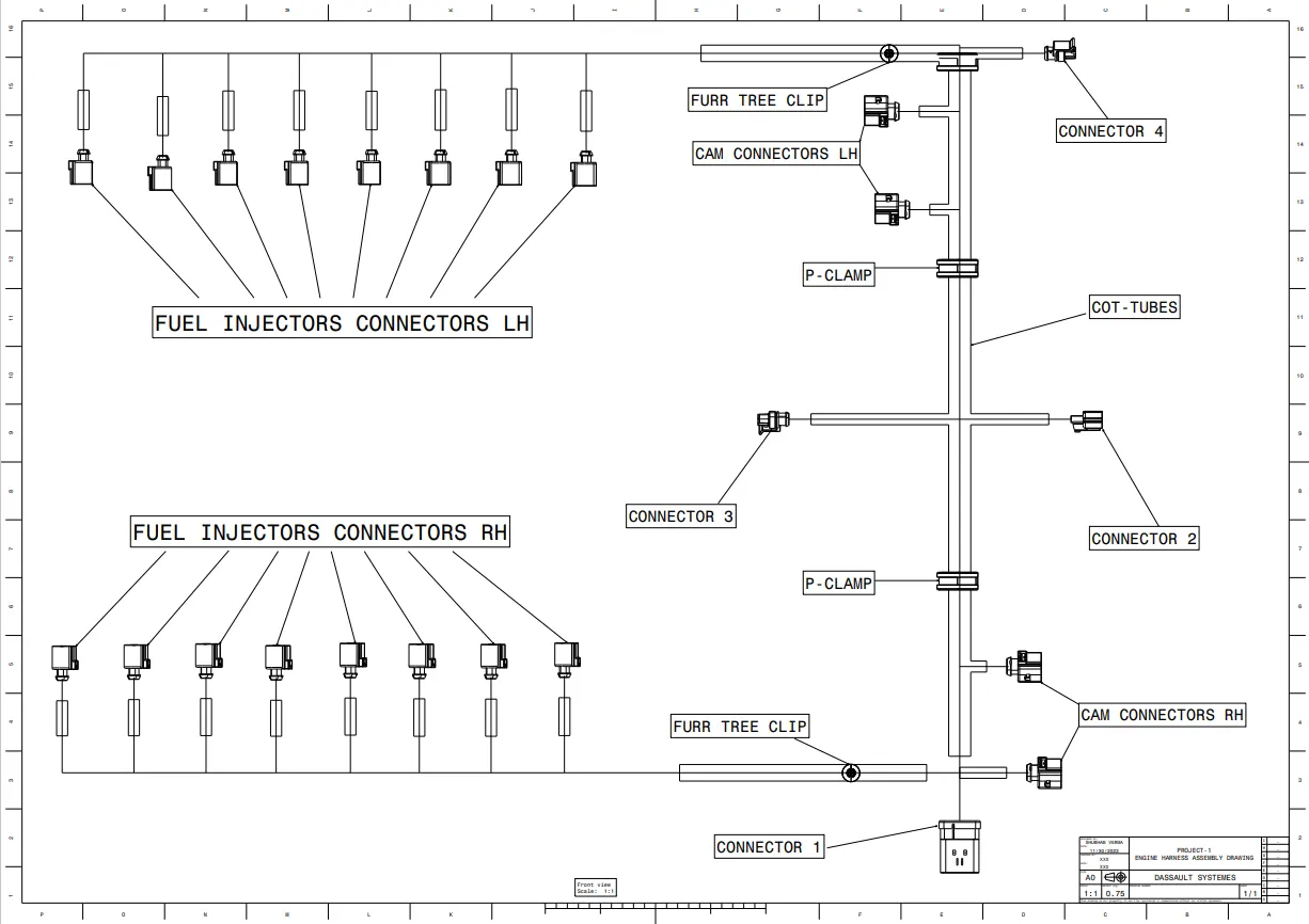
open a new drawing file and Select front view command, then go to the flattened harness window and select a suitable face to create drafting of the harness.
to make the bundle segments visible right click on the drawing sheet and go to properties, in the view tab, highlight '3D wireframe' and 'is always visible' in the dress up settings.
GOOGLE DRIVE LINK FOR ENGINE WIRING HARNESS FILE :-
https://drive.google.com/file/d/10EzG3JGj2Xug2a5-C59HzL_oHkWRXQ5e/view?usp=sharing