Project 1
PROJECT 1
Q.1 ) Design a battery pack for a car roughly 150 Kw with 120 V. Use 3500 mAh 3.6V nominal NMC chemistry cell.
a. Design the battery pack configuration.
b. Draw the BMS topology for this battery pack.
Aim -: Design a battery pack for a car roughly 150 Kw with 120 V. Use 3500 mAh 3.6V nominal NMC chemistry cell.
Introduction -:
Batteries achieve the desired operating voltage by connecting several cells in series; each cell adds its voltage potential to derive at the total terminal voltage. Parallel connection attains higher capacity by adding up the total ampere-hour (Ah). Some packs may consist of a combination of series and parallel connections. Laptop batteries commonly have four 3.6V Li-ion cells in series to achieve a nominal voltage 14.4V and two in parallel to boost the capacity from 2,400mAh to 4,800mAh. Such a configuration is called 4s2p, meaning four cells in series and two in parallel. Insulating foil between the cells prevents the conductive metallic skin from causing an electrical short.
Most battery chemistries lend themselves to series and parallel connection. It is important to use the same battery type with equal voltage and capacity (Ah) and never to mix different makes and sizes. A weaker cell would cause an imbalance. This is especially critical in a series configuration because a battery is only as strong as the weakest link in the chain. An analogy is a chain in which the links represent the cells of a battery connected in series (Figure 1).

A weak cell may not fail immediately but will get exhausted more quickly than the strong ones when on a load. On charge, the low cell fills up before the strong ones because there is less to fill and it remains in over-charge longer than the others. On discharge, the weak cell empties first and gets hammered by the stronger brothers. Cells in multi-packs must be matched, especially when used under heavy loads.
Series Connection-:
Portable equipment needing higher voltages use battery packs with two or more cells connected in series. Figure 2 shows a battery pack with four 3.6V Li-ion cells in series, also known as 4S, to produce 14.4V nominal. In comparison, a six-cell lead acid string with 2V/cell will generate 12V, and four alkaline with 1.5V/cell will give 6V.

Adding cells in a string increases the voltage; the capacity remains the same.
If you need an odd voltage of, say, 9.50 volts, connect five lead acid, eight NiMH or NiCd, or three Li-ion in series. The end battery voltage does not need to be exact as long as it is higher than what the device specifies. A 12V supply might work in lieu of 9.50V. Most battery-operated devices can tolerate some over-voltage; the end-of-discharge voltage must be respected, however.
High voltage batteries keep the conductor size small. Cordless power tools run on 12V and 18V batteries; high-end models use 24V and 36V. Most e-bikes come with 36V Li-ion, some are 48V. The car industry wanted to increase the starter battery from 12V (14V) to 36V, better known as 42V, by placing 18 lead acid cells in series. Logistics of changing the electrical components and arcing problems on mechanical switches derailed the move.
Some mild hybrid cars run on 48V Li-ion and use DC-DC conversion to 12V for the electrical system. Starting the engine is often done by a separate 12V lead acid battery. Early hybrid cars ran on a 148V battery; electric vehicles are typically 450–500V. Such a battery needs more than 100 Li-ion cells connected in series.
High-voltage batteries require careful cell matching, especially when drawing heavy loads or when operating at cold temperatures. With multiple cells connected in a string, the possibility of one cell failing is real and this would cause a failure. To prevent this from happening, a solid state switch in some large packs bypasses the failing cell to allow continued current flow, albeit at a lower string voltage.
Parallel Connection-:
If higher currents are needed and larger cells are not available or do not fit the design constraint, one or more cells can be connected in parallel. Most battery chemistries allow parallel configurations with little side effect. Figure 4 illustrates four cells connected in parallel in a P4 arrangement. The nominal voltage of the illustrated pack remains at 3.60V, but the capacity (Ah) and runtime are increased fourfold.

A cell that develops high resistance or opens is less critical in a parallel circuit than in a series configuration, but a failing cell will reduce the total load capability. It’s like an engine only firing on three cylinders instead of on all four. An electrical short, on the other hand, is more serious as the faulty cell drains energy from the other cells, causing a fire hazard. Most so-called electrical shorts are mild and manifest themselves as elevated self-discharge.
Series/parallel Connection -:
The series/parallel configuration shown in Figure 6 enables design flexibility and achieves the desired voltage and current ratings with a standard cell size. The total power is the sum of voltage times current; a 3.6V (nominal) cell multiplied by 3,400mAh produces 12.24Wh. Four 18650 Energy Cells of 3,400mAh each can be connected in series and parallel as shown to get 7.2V nominal and a total of 48.96Wh. A combination with 8 cells would produce 97.92Wh, the allowable limit for carry on an aircraft or shipped without Class 9 hazardous material. (See BU-704a: Shipping Lithium-based Batteries by Air) The slim cell allows flexible pack design but a protection circuit is needed.
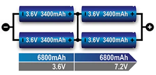
Terminology to describe Series and Parallel Connection -:
The battery industry specifies the number of cells in series first, followed by the cells placed in parallel. An example is 2s2p. With Li-ion, the parallel strings are always made first; the completed parallel units are then placed in series. Li-ion is a voltage based system that lends itself well for parallel formation. Combining several cells into a parallel and then adding the units serially reduces complexity in terms of voltages control for pack protection.
Building series strings first and then placing them in in parallel may be more common with NiCd packs to satisfy the chemical shuttle mechanism that balances charge at the top of charge. “2s2p” is common; white papers have been issued that refer to 2p2s when a serial string is paralleled.
Safety devices in Series and Parallel Connection-:
Positive Temperature Coefficient Switches (PTC) and Charge Interrupt Devices (CID) protect the battery from overcurrent and excessive pressure. While recommended for safety in a smaller 2- or 3-cell pack with serial and parallel configuration, these protection devices are often being omitted in larger multi-cell batteries, such as those for power tool. The PTC and CID work as expected to switch of the cell on excessive current and internal cell pressure; however the shutdown occurs in cascade format. While some cells may go offline early, the load current causes excess current on the remaining cells. Such overload condition could lead to a thermal runaway before the remaining safety devices activate.
Some cells have built-in PCT and CID; these protection devices can also be added retroactively. The design engineer must be aware than any safety device is subject to failure. In addition, the PTC induces a small internal resistance that reduces the load current.
Types of battery management systems
Battery management systems range from simple to complex and can embrace a wide range of different technologies to achieve their prime directive to “take care of the battery.” However, these systems can be categorized based on their topology, which relates to how they are installed and operate upon the cells or modules across the battery pack.
i. Centralized BMS Architecture
It has one central BMS in the battery pack assembly. All the battery packages are connected to the central BMS directly. The structure of a centralized BMS is shown in the figure below. The centralized BMS has some advantages. It is more compact, and it tends to be the most economical since there is only one BMS. However, there are disadvantages to a centralized BMS. Since all the batteries are connected to the BMS directly, the BMS needs a lot of ports to connect with all the battery packages. This translates to lots of wires, cabling, connectors, etc. in large battery packs, which complicates both troubleshooting and maintenance.
ii. Modular BMS Topology
Similar to a centralized implementation, the BMS is divided into several duplicated modules, each with a dedicated bundle of wires and connections to an adjacent assigned portion of a battery stack. In some cases, these BMS submodules may reside under a primary BMS module oversight whose function is to monitor the status of the submodules and communicate with peripheral equipment. Thanks to the duplicated modularity, troubleshooting and maintenance are easier, and extension to larger battery packs is straightforward. The downside is overall costs are slightly higher, and there may be duplicated unused functionality depending on the application.
iii. Primary/Subordinate BMS
Conceptually similar to the modular topology, however, in this case, the slaves are more restricted to just relaying measurement information, and the master is dedicated to computation and control, as well as external communication. So, like the modular types, the costs may be lower since the functionality of the slaves tends to be simpler, with likely less overhead and fewer unused features.
iv. Distributed BMS Architecture
Considerably different from the other topologies, where the electronic hardware and software are encapsulated in modules that interface to the cells via bundles of attached wiring. A distributed BMS incorporates all the electronic hardware on a control board placed directly on the cell or module that is being monitored. This alleviates the bulk of the cabling to a few sensor wires and communication wires between adjacent BMS modules. Consequently, each BMS is more self-contained and handles computations and communications as required. However, despite this apparent simplicity, this integrated form does make troubleshooting and maintenance potentially problematic, as it resides deep inside a shield module assembly. Costs also tend to be higher as there are more BMSs in the overall battery pack structure.
Importance of battery management systems
Functional safety is of the highest importance in a BMS. It is critical during charging and discharging operations, to prevent the voltage, current, and temperature of any cell or module under supervisory control from exceeding defined SOA limits. If limits are exceeded for a length of time, not only is a potentially expensive battery pack compromised, but dangerous thermal runaway conditions could ensue. Moreover, lower voltage threshold limits are also rigorously monitored for the protection of the lithium-ion cells and functional safety. If the Li-ion battery stays in this low-voltage state, copper dendrites could eventually grow on the anode, which can result in elevated self-discharge rates and raise possible safety concerns. The high energy density of lithium-ion powered systems comes at a price that leaves little room for battery management error. Thanks to BMSs, and lithium-ion improvements, this is one of the most successful and safe battery chemistries available today.
The performance of the battery pack is the next highest important feature of a BMS, and this involves electrical and thermal management. To electrically optimize the overall battery capacity, all the cells in the pack are required to be balanced, which implies that the SOC of adjacent cells throughout the assembly are approximately equivalent. This is exceptionally important because not only can optimal battery capacity be realized, but it helps prevent general degradation and reduces potential hotspots from overcharging weak cells. Lithium-ion batteries should avoid discharge below low voltage limits, as this can result in memory effects and significant capacity loss. Electrochemical processes are highly susceptible to temperature, and batteries are no exception. When environmental temperature drops, capacity and available battery energy roll off significantly. Consequently, a BMS may engage an external in-line heater that resides on, say, the liquid cooling system of an electric vehicle battery pack, or turn on resident heater plates that are installed underneath modules of a pack incorporated within a helicopter or other aircraft. Additionally, since charging frigid lithium-ion cells is detrimental to battery life performance, it is important to first elevate the battery temperature sufficiently. Most lithium-ion cells cannot be fast-charged when they are less than 5°C and should not be charged at all when they are below 0°C. For optimum performance during typical operational usage, BMS thermal management often ensures that a battery operates within a narrow Goldilocks region of operation (e.g. 30 – 35°C). This safeguards performance, promotes longer life, and fosters a healthy, reliable battery pack.
Calculations -:
Design a battery pack for a car roughly 150 Kw with 120 V. Use 3500 mAh 3.6V nominal NMC chemistry cell.
Given-
CAR Specifications-
Rated power rating - 150kW
Rated Voltage - 120V
Battery Specifications-
Nominal capacity - 3500mAH
Nominal cell voltage - 3.6V
Now, We have to calculatenumber of cells to be connected in series and parallell.
No of ceels in series = Rated Voltage / Nominal cell voltage
No of ceels in series = 120 / 3.6
No of ceels in series = 33.33
Rounding off the number of cells depends on maximum & minimum motor voltage
case 1. Rounding off to 33
Nominal battery voltage = cell nom. vtg * 33
Nominal battery voltage = 3.6*33
Nominal battery voltage = 118.8v
Case 2. Rounding off to 34
Nominal battery voltage = cell nom. vtg * 34
Nominal battery voltage = 3.6*34
Nominal battery voltage = 122.4v
It's always better to have more voltage. So, we can pick case 2. with 34 cells in series.
Current I = Power / Voltage
I = 150KW / 120V
Rated Current I = 1250A
No. of cells in parallel = Rated current / Cell capacity
No. of cells in parallel = 1250 / 3500mA
No. of cells in parallel = 357.14
Case 1. Rounding off to 357
Battery capacity = 3500mA * 357
Battery capacity = 1249.5AH
Case 2. Rounding off to 358
Battery capacity = 3500mA * 358
Battery capacity = 1253AH
It's always recommended to discharge the battery for continuous current in 1C. Hence, we will choose 358 cells in parallel.
The battery pack configuration is 34S358P.
Total number of cells = 34 x 358 = 12172
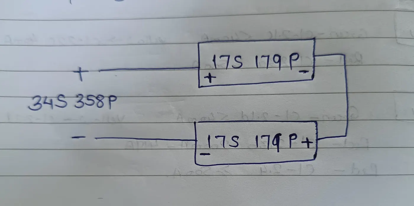
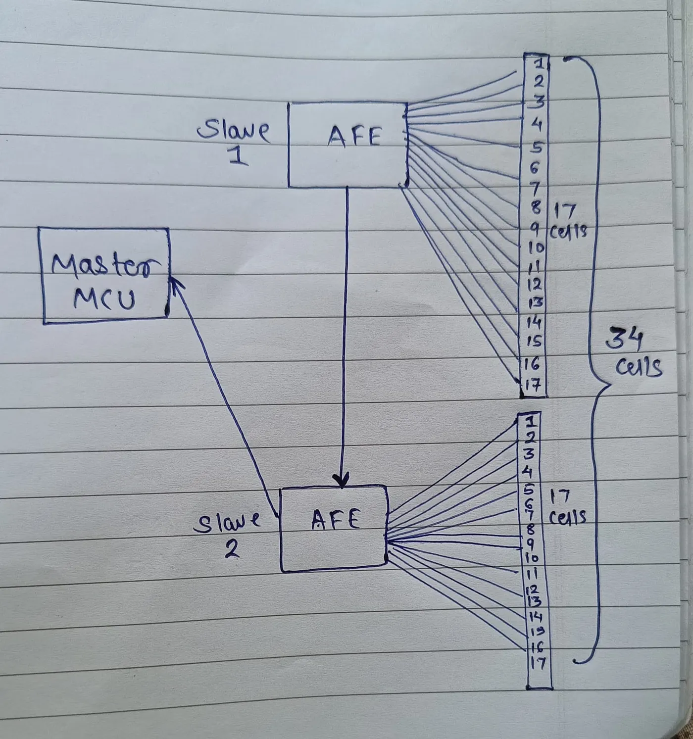
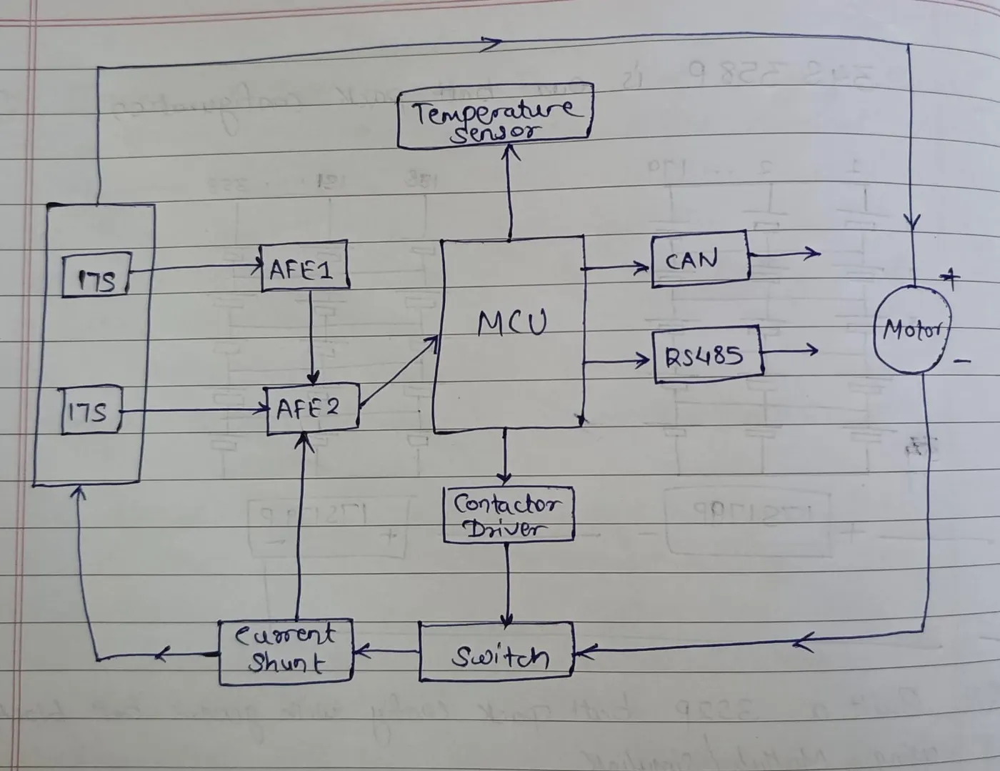
b. The BMS topology for this battery pack would be Master-Slave Topology because the battery pack consists of more than 18 cells in series.
In the below figure, the Master-Slave Topology consists of 2 slaves (AFEs).
Slave 1 consists of 17 cells in series.
Slave 2 consists of 17 cells in series.
Q.2 )Build a 3S2P battery pack configuration with generic battery block using Matlab/Simulink.
AIM: To build a 3S2P battery pack configuration with a generic battery block using MATLAB/Simulink.
SIMULINK MODEL:
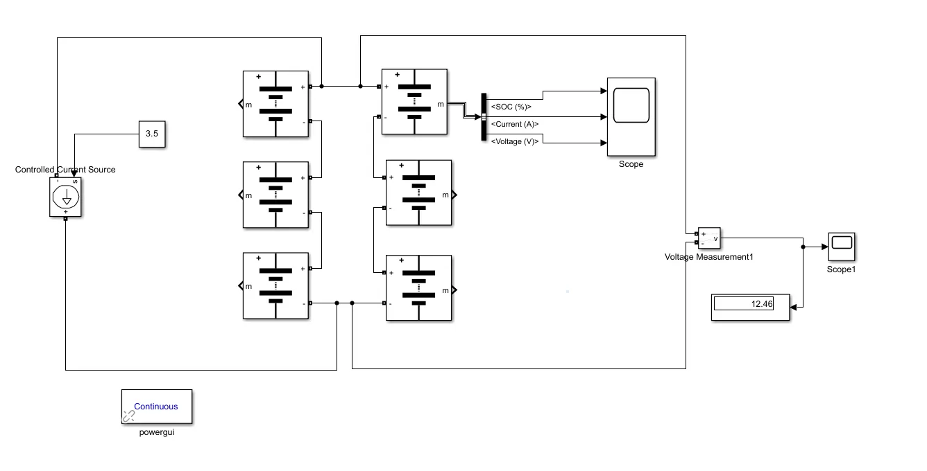
CALCULATION:
Total number of cells in battery pack = 3 x 2 = 6
Nominal voltage of cell = 3.6 V
Nominal capacity = 3.5 Ah
Nominal voltage of battery pack = no. of cells in series x nominal voltage of the cell
= 3 x 3.6 = 10.8 V
Rated capacity of battery pack = no. of cells in parallel x rated capacity of the cell
= 2 x 3.5 = 7 Ah
Overall voltage of the battery pack = maximum capacity of the cell x no. of cells in series
= 4.2 x 3 = 12.6 V
RESULT:
The voltage is dropped from 12.57 V to 12.46 V for this battery pack.
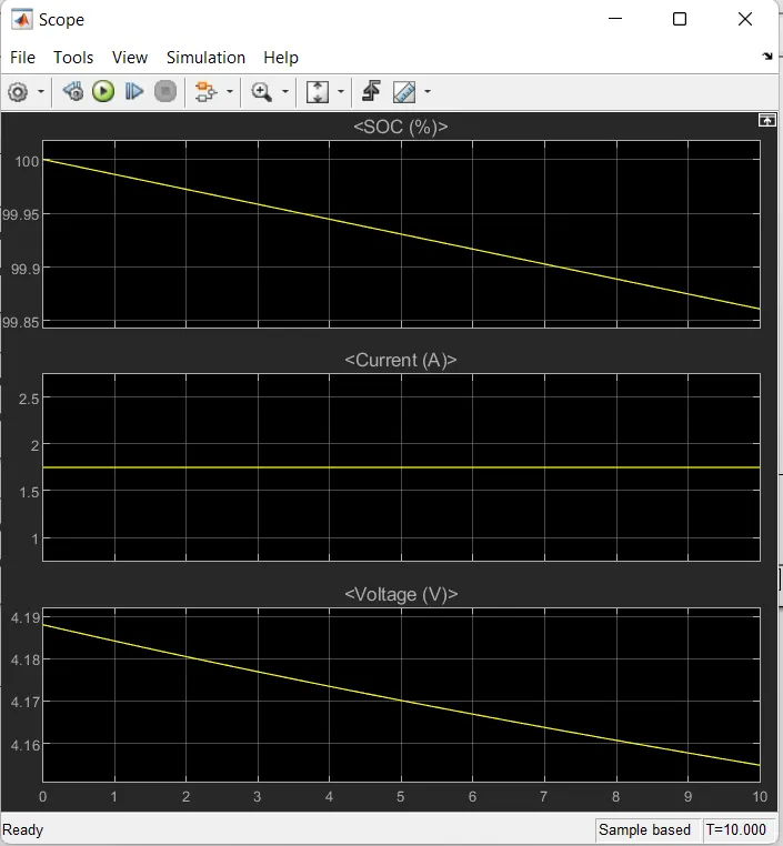
The first plot shows the SOC of the cell. It dropped from 100% to 99.86%.
The second plot shows the current of the cell. It is nearly 1.8 A.
The third plot shows the voltage of the cell. It dropped from approx. 4.19 V to 4.155 V.
CONCLUSION:
Hence, the 3S2P battery pack configuration is built with the generic battery block using MATLAB/Simulink.