Project 1
Aim:
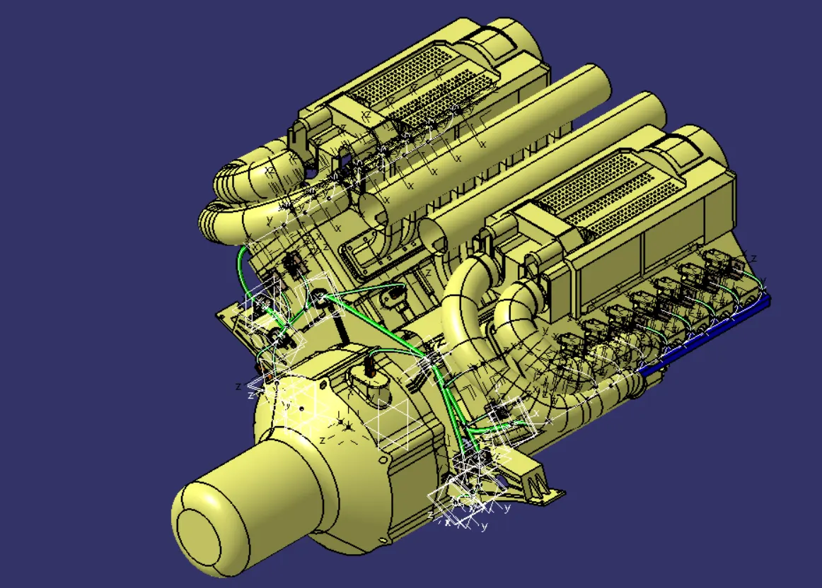
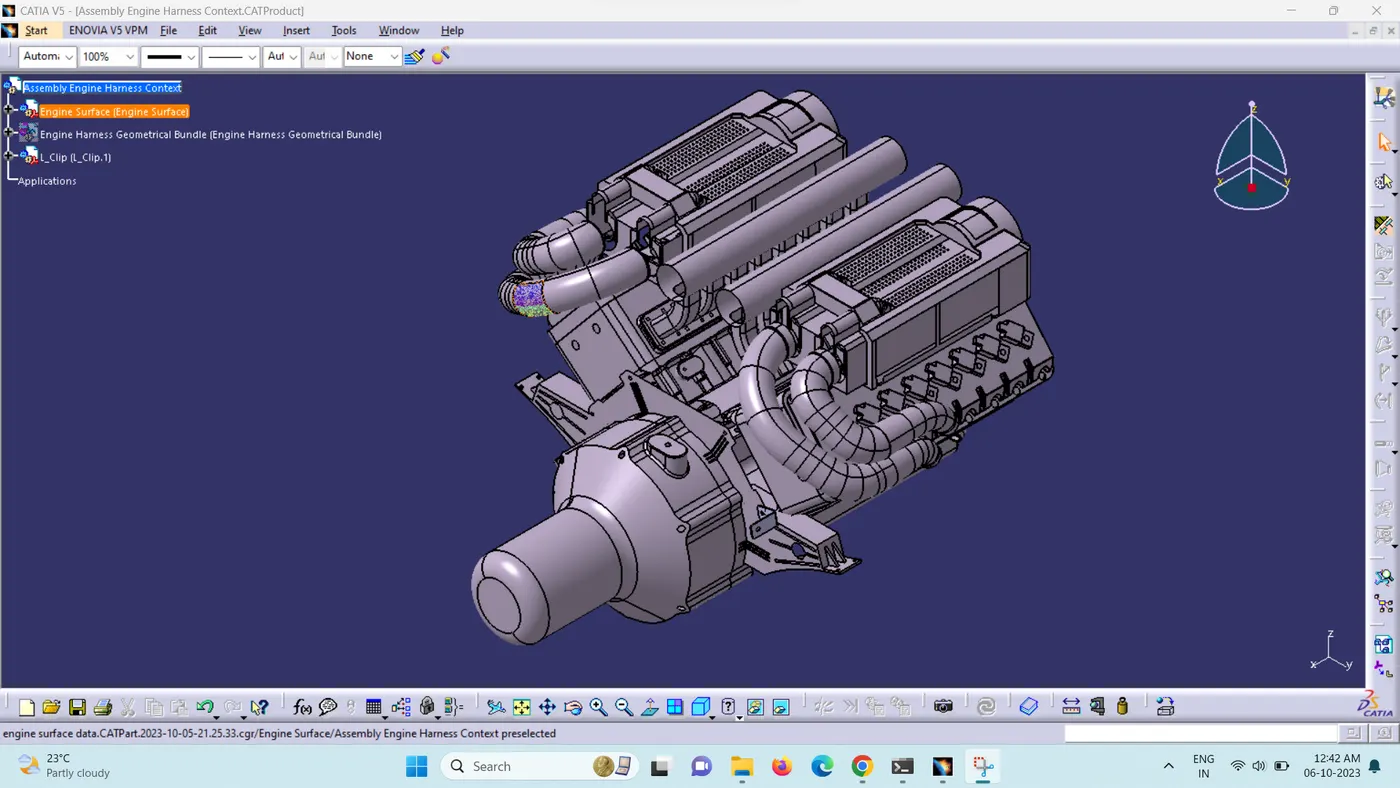
To route the wiring harness on given Engine and flatten view drawing in CATIA V5.
Route the Wiring harness on Given Engine and Prepare flatten view drawing in CATIA V5. Application of all Packaging rules, Industry best practices studied in this course shall be demonstrated in design. Apply Protection coverings as required.
Available connector 3D data can be used, or you can download the connectors from www.te.com
Prepare & Submit all necessary reports like clearance, Clipping/Clamping selection, Harness fixing requirements, Harness continuity, Assumptions if any along with CATIA 3D data.
Electrical connector: An electrical connector is a device or mechanism used to establish a physical and electrical connection between two or more electrical circuits or components. Connectors enable the transfer of electrical signals, power, or data between different devices or systems. They come in various shapes, sizes, and configurations to accommodate different requirements, such as the number of pins or terminals, the type of signal being transferred (analog or digital), the environment in which they will be used (indoor, outdoor, harsh conditions), and more.
Electrical connectors typically consist of two main parts:
-
Plug: This is the male component of the connector, usually having protruding pins, prongs, or sockets that match with corresponding receptacles in the female component.
-
Receptacle: This is the female component of the connector, designed to accept the plug and create a secure electrical connection with its pins, prongs, or sockets.
Wire: Wires are essential components of wire harnesses, which are organized assemblies of multiple wires, cables, or conductors that are bound together in a specific arrangement and encased in a protective covering. Wire harnesses are used to transmit electrical signals or power between various components, devices, or systems within a larger structure, such as an automobile, aircraft, industrial machinery, or electronic equipment.
Protective Covering: The protective covering in a wire harness serves as a barrier that shields the individual wires and cables within the harness from various environmental factors and mechanical stresses. This covering not only provides physical protection but also contributes to the overall organization, durability, and reliability of the wire harness. There are different types of protective coverings used in wire harnesses, each designed to address specific requirements and conditions.
Ex: Heat Shrink Tubing, Conduit, Tape, Loom, Cable Tie, Spiral Wrap, Connector Boots, Grommets, Heat-resistant Sleeving.
Ensure the following points while creating the wiring harness to apply all packaging rules and industry best practices.
- Provide clips/clamps as per the requirement.
- Ensure that there are no instances of wires tangling while designing the wire harness.
- Additional clips/clamps may be used to prevent tangling.
- Allow for additional slack if needed. A 5-10% slack is deemed sufficient.
- Avoid routing over bolts and bolted joints to prevent puncturing of the harness.
- Avoid routing on sharp edges; otherwise, provide protection for the harness.
- Adhere to the clearance distance and keep the harness away from components generating heat.
- Provide protection as needed according to the surrounding temperature.
- Refrain from providing direct support for the harness on fuel lines routed in the engine.
- Utilize plastic guiding channels if necessary.
- Ensure that the branch length is greater than 50mm.
- Maintain a minimum distance of at least 50mm between two branch points.
- Maintain a minimum distance of at least 25mm between a clip and a branch point.
- Minimize the use of sheet metal brackets on the engine. Utilize available threaded bosses on the engine or request them as needed.
- The wiring harness should be designed for easy assembly and accessibility.
- When using dummy connectors, ensure that the positions defined are practical. Bundle diameters and other placements should be accurately defined for the wire harness routing.
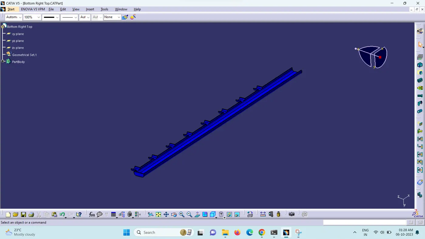
- In cases where the packaging area is too confined and numerous packaging constraints are present, consider creating a harness channel. This can be used to route and effectively protect the wire harness."
Step 1:
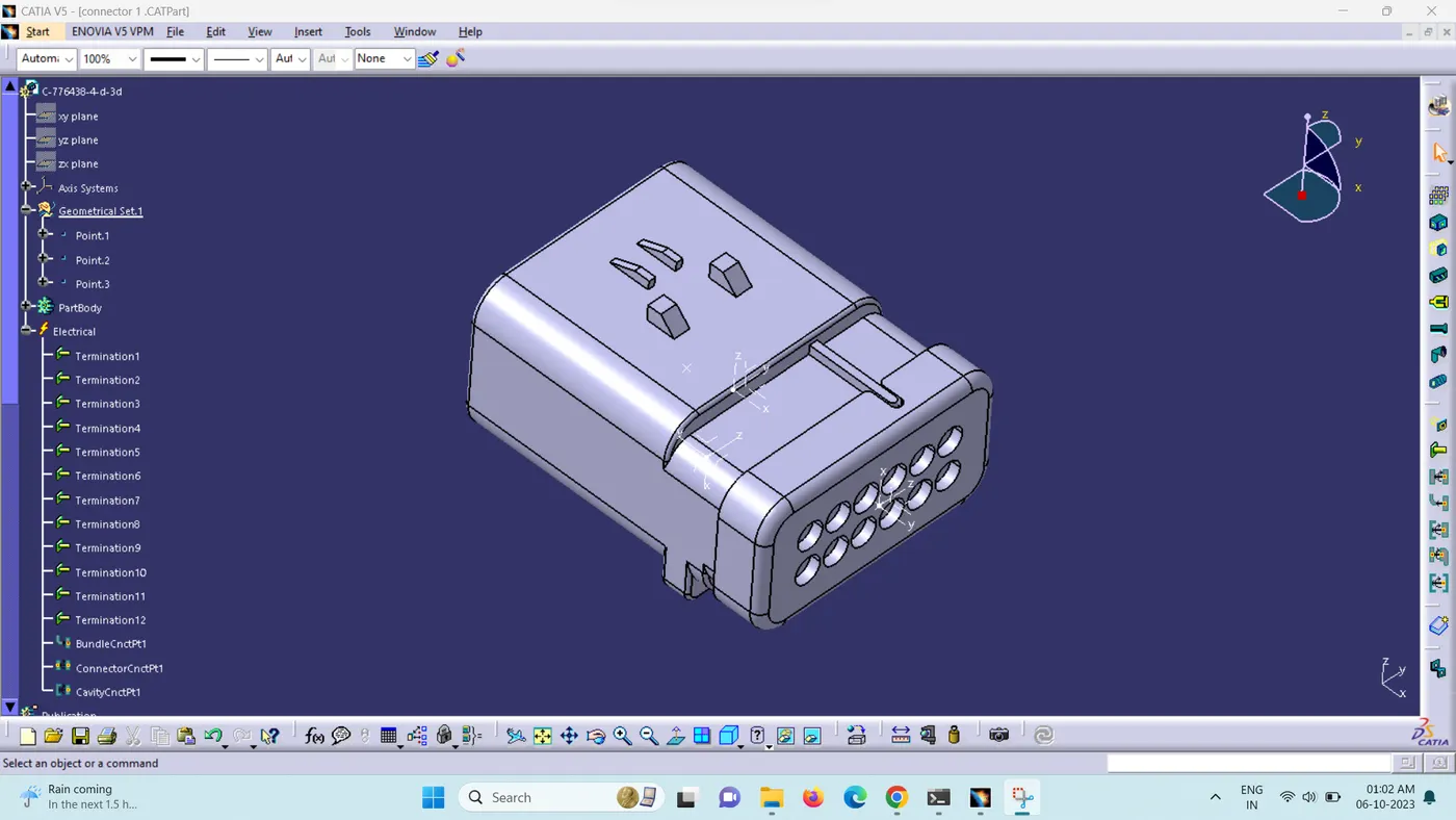
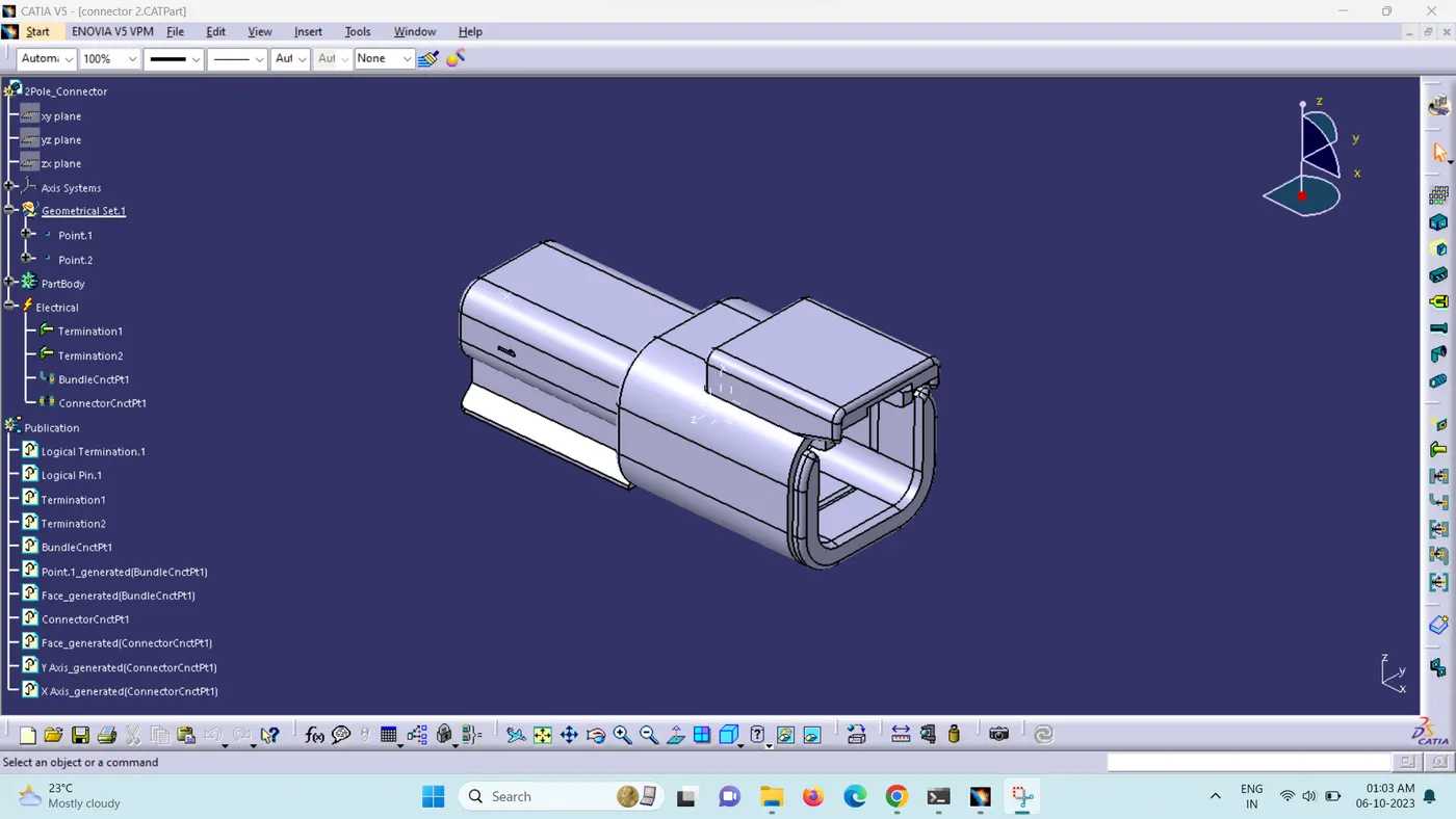
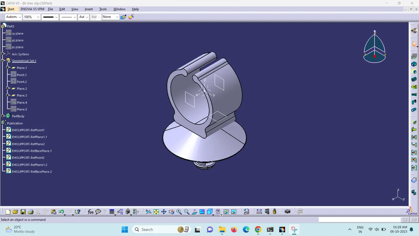
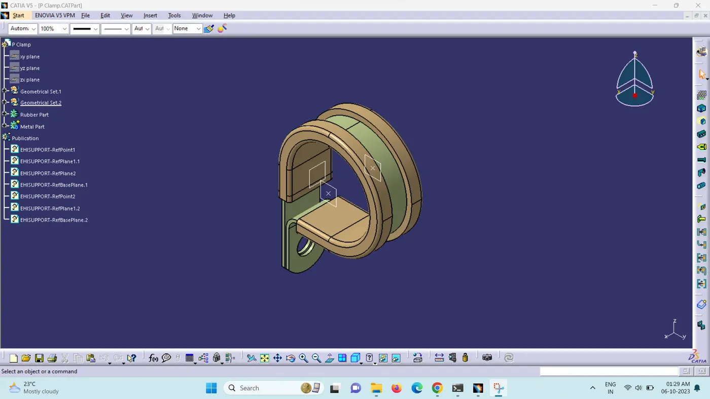
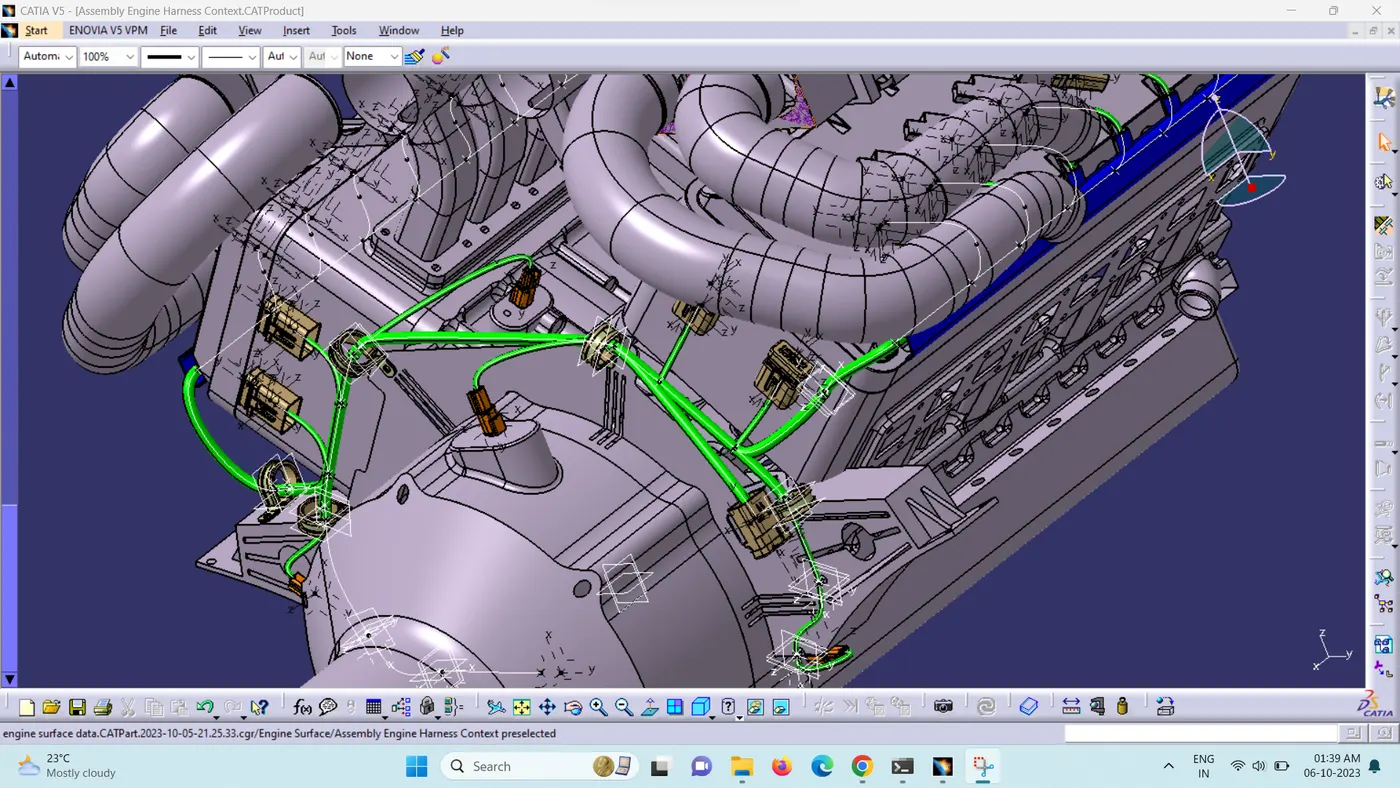
First, we have to define the points and planes of the Electrical and mechanical parts and then we have to define them electrically.
Step 2:
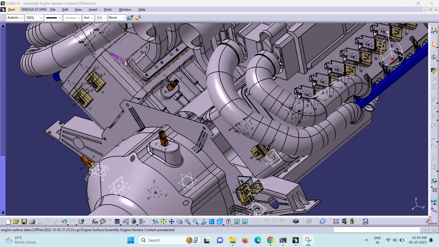
Place the connectors in the defined positions.
Step 3:
Place the clips and clamps in the positions you see fit, i.e, we take chassis routing from right side so we started routing from right side and start routing.
Step 4:
After Completing the wiring harness to the engine check for the connectivity, since every wire should be contineous.
Checking bundle continuity
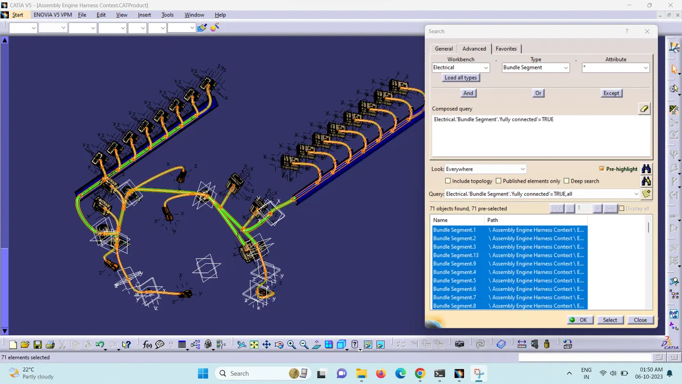
- In this step, first, we need to ensure that "multi-branchable" is selected. Then, navigate to Edit > Search > Advanced > Workbench-Electrical > Type-Bundle Segment > Attribute-Fully Connected.
- Selecting the 'True' option will display all the connected bundle segments, while selecting 'False' will show all the non-connected bundle segments.
- For this task, we have chosen the 'True' option and conducted the search. As seen in the figure below, all the bundle segments are highlighted, confirming that they are electrically connected.
Step 5:
Creating flatten view of the engine harness geometrical bundle assembly.
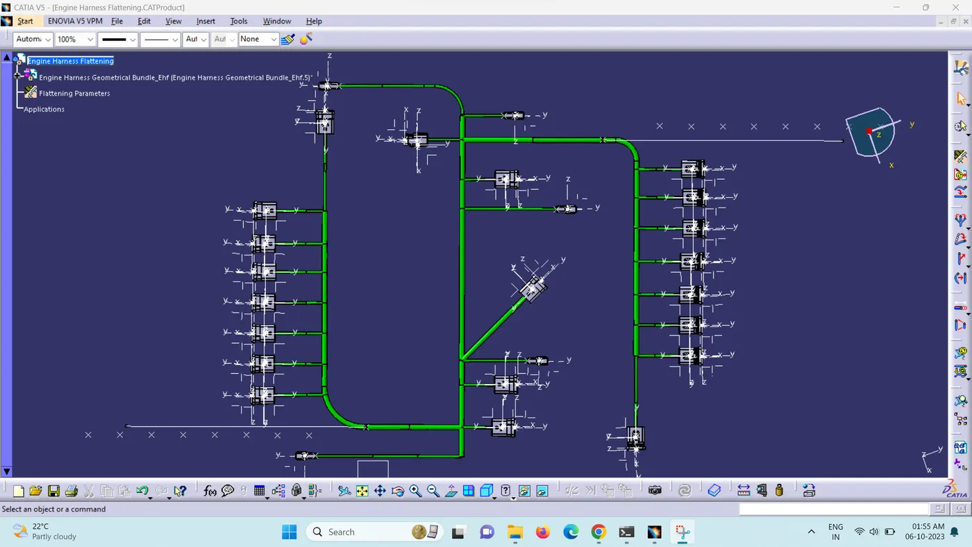
In this step, for creating flatten view we have to work in Electrical Harness Flattening workbench of Catia V5.
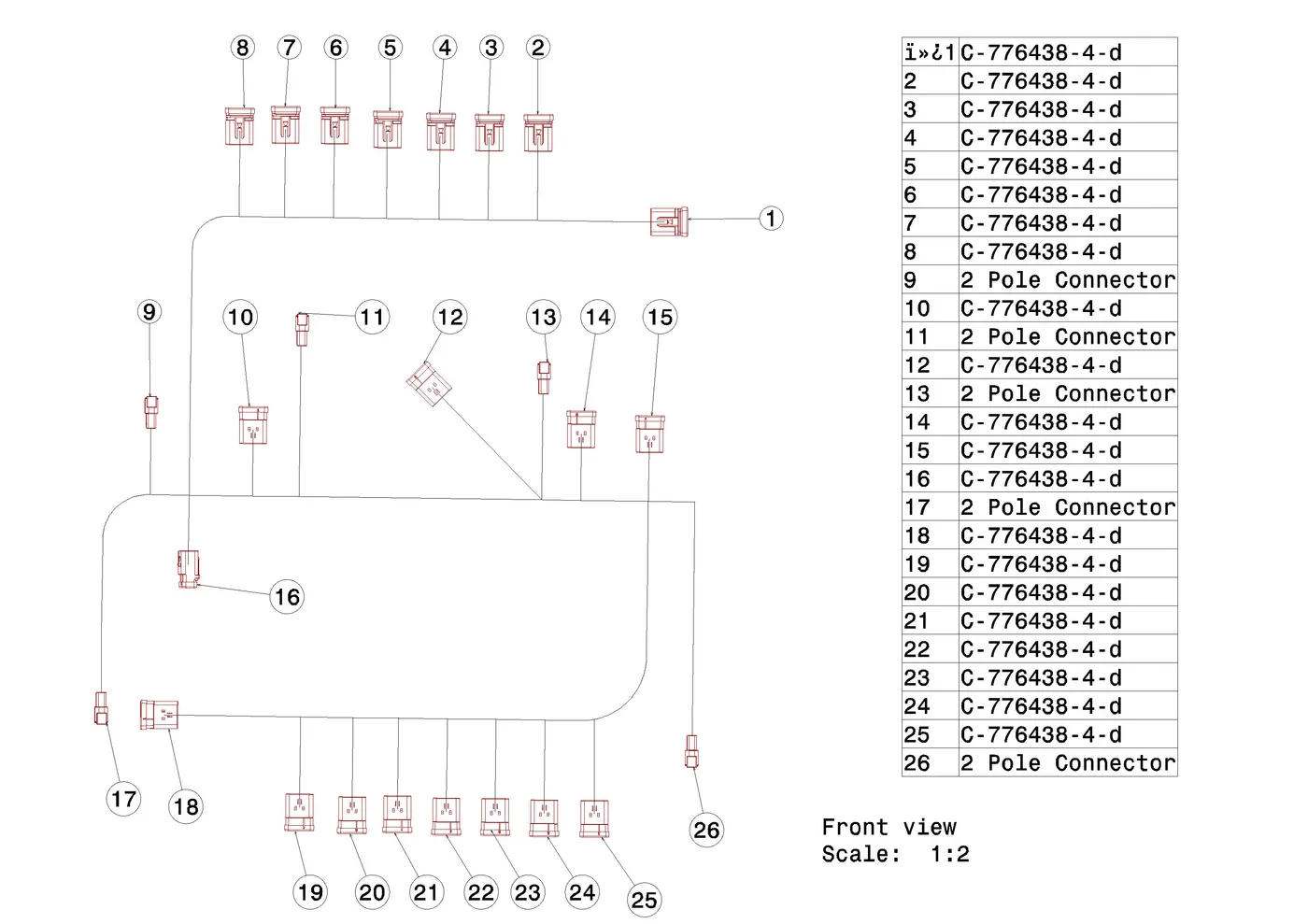
We have extracted the bundle assembly into Engine Harness Flattening Product file and then flattened the file along face of the interconnection connector as shown in below figure.
At this stage, for clarity, we have hidden the flattening diagram of the plastic guiding channels from the drawing view.
Conclusion:
In this way, we have routed wiring harness for the Engine. Also, prepared flatten view drawing with proper sheet in CATIA V5.