Project 1
Project 1
1. Design a multi-storey Residential Building located in Bangalore using STAAD Pro Connect Edition. The specification must be as follows:
|
Building floors |
G + 6 + R |
|
Plan dimension |
B = 25m , L = 16m |
|
Storey Height |
h = 3.5m |
|
Soil |
Hard soil |
|
Use |
Residential Purpose |
|
Safe Bearing Capacity |
180 kN/m2 |
|
Maximum slab thickness |
150mm |
Assume suitable sections for structural elements. Follow IS456, IS1893 and IS 875
- Prepare a Design Basis Report for the project
- Create structural model using STAAD Pro Connect Edition
- Prepare DL, LL, WL and EQL load calculations as per IS 875 standards
- Design slab element using MS – Excel
- Design beam and column element using STAAD RCDC. Attach the design calculation report.
- Design Foundations using STAAD Foundation.
- Prepare bar bending schedule for beam and column using STAAD RCDC
- Attach necessary sketches and drawings wherever required.
- All stipulations, assumptions and design parameter must adhere to Indian Standards.
AIM:
To design a multi-storey Residential Building located in Bangalore using STAAD Pro
INTRODUCTION:
STAAD Pro is a popular structural analysis application known for analysis, diverse applications of use, interoperability, and time-saving capabilities. It helps structural engineers perform 3D structural analysis and design for both steel and concrete structures.
PROCEDURE:
Design Basis Report:
Given data:
Building Floors : G+6+R
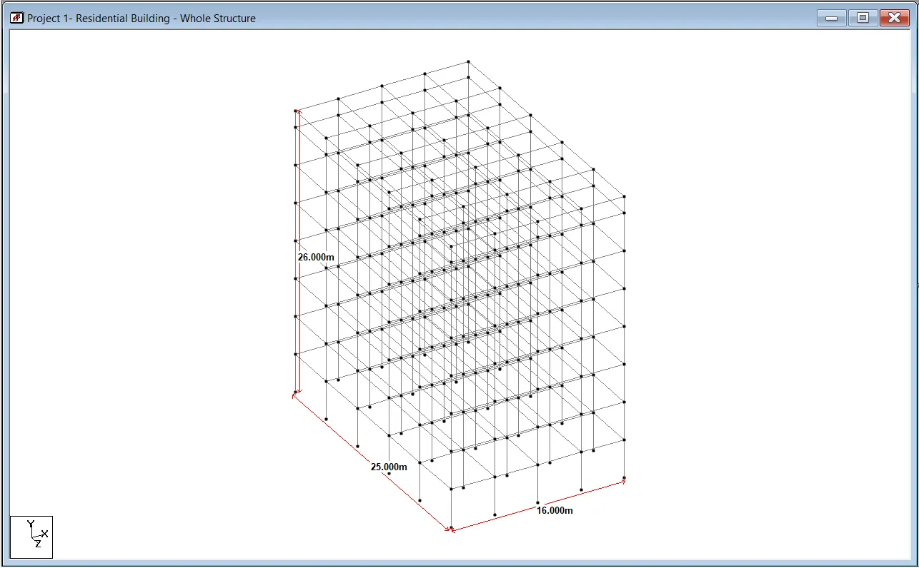
Plan Dimension : B=25m, L=16m
Story Height : h = 3.5m
Soil : Hard soil
<!-- [if gte msEquation 12]>Use : Residential purpose
Safe Bearing Capacity : 180 kN/m2
Maximum slab thickness : 150mm
Assume:
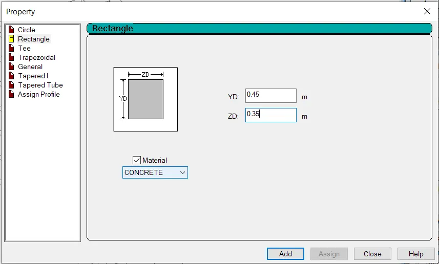
Beam size = 300mm X 450mm
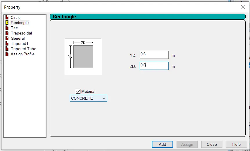
Column size = 600mm X 600mm
Load Calculations:
Dead Load on Floor: (IS 875 Part-)
(Unit weight of concrete = 25 kN/m2)
Dead load due to slab = 0.15 x 25 = 3.75 kN/m2
Partitions : 1.5 kN/m2
Floor Finish : 2.5 kN/m2
Miscellaneous : 1 kN/m2
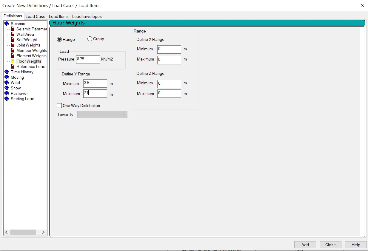
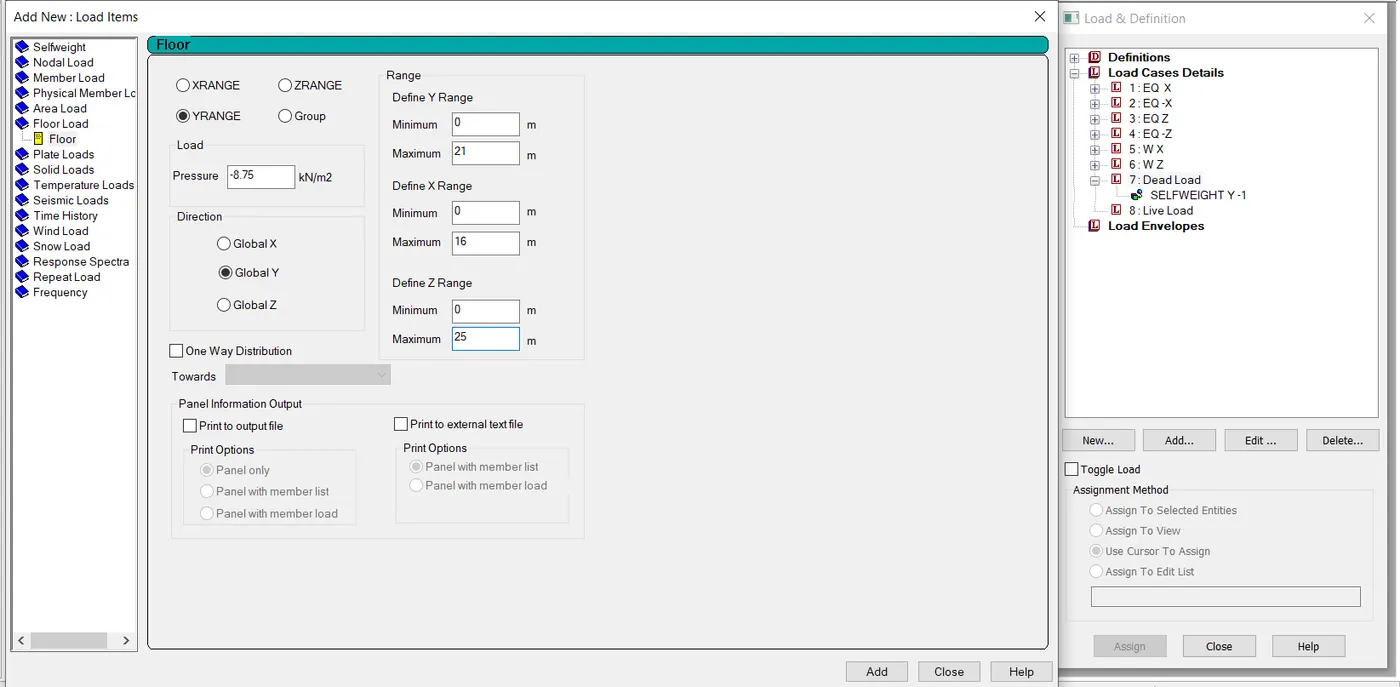
Total Floor Load = 8.75 kN/m2
Dead Load on Roof: (IS 875 part-1)
Dead load on roof slab = 3.75 kN/m2
Water proofing = 0.5 kN/m2
MEP services = 0.5 kN/m2
Miscellaneous = 0.5 kN/m2
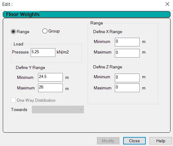
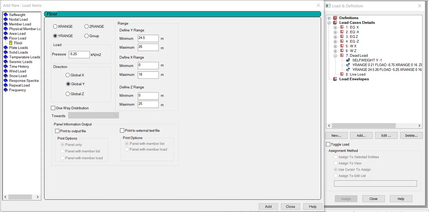
Total Roof load = 5.25 kN/m2
Live Load: (IS 875 Part-2)
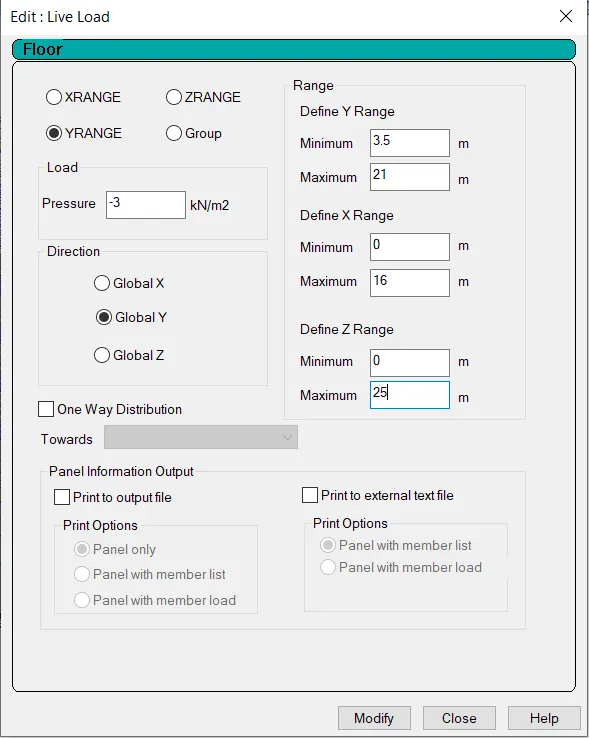
For residential building, LL = 3 kN/m2
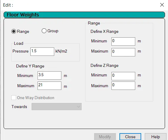
For roof, LL = 1.5 kN/m2
Wind Load: (IS 875 Part-3)
| Calculation of Wind Load (IS 875 - Part 3) | |||||||
| Design Wind Speed | Vz | = | Vb k1 k2 k3 k4 m/s | ||||
| Basic Wind Speed | Vb | = | 33 m/s | ||||
| Probability factor | k1 | = | 1 | ||||
| Terrain factor , Category | for k2 | = | Category 4, Class B | ||||
| Topography factor | k3 | = | 1 | ||||
| Design Wind Pressure | Pz | = | 0.6 Vz2 | ||||
| Height | k2 | Vz | Pz | Pz in kN | |||
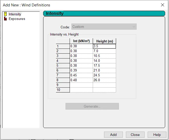
| 3.5 | 0.76 | 25 | 377.40 | 0.38 | |||
| 7.0 | 0.76 | 25 | 377.40 | 0.38 | |||
| 10.5 | 0.76 | 25 | 377.40 | 0.38 | |||
| 14.0 | 0.76 | 25 | 377.40 | 0.38 | |||
| 17.5 | 0.76 | 25 | 377.40 | 0.38 | |||
| 21.0 | 0.77 | 25 | 387.40 | 0.39 | |||
| 24.5 | 0.83 | 27 | 450.13 | 0.45 | |||
| 26.0 | 0.86 | 28 | 483.25 | 0.48 | |||
Seismic Load:
Calculation of seismic load (IS 1893:2016 part-1)
| Design Base Shear | VB | = | Ah W kN | ||||||||||
| Design Horizontal Acceleration Coefficient | |||||||||||||
| Ah | = | ((Z/2).(Sa/g))/(R/I) | |||||||||||
| Zone factor | Z | = | 0.1 | (Banglore: zone II, CL-6.4.2, TL-3) | |||||||||
| Soil Condition factor , Sa / g | <!-- [if gte vml 1]> <!-- [if gte msEquation 12]> |
||||||||||||
| T | = | ||||||||||||
| Height of building | h | = | 26m | ||||||||||
| Base dimension of building | Along X | = | 16m | ||||||||||
| Along Z | = | 25m | |||||||||||
| T along X | = | 0.59s | |||||||||||
| T along Z | = | 0.47s | |||||||||||
| Sa / g | = | 2.325 | 2.906 | ||||||||||
| Response Reduction Factor | R | = | 5 | ||||||||||
| Importance Factor | I | = | 1 | ||||||||||
| Horizontal Acceleration Coefficient | Ah | = | 0.0232 | ||||||||||
| Ah | = | 2.3248 % | |||||||||||
| Seismic Weight | |||||||||||||
| Area of Each floor | A | = | 400 m2 | ||||||||||
| Due to Dead Loads , Typical Floor | DL | = | 8.75 kN/m2 | ||||||||||
| W DL | = | 3500 kN | |||||||||||
| Due to Dead Loads ,Roof | DL roof | = | 5.25 kN/m2 | ||||||||||
| ` | = | 2100 kN | |||||||||||
| Due to Live Loads , Typical Floor | LL | = | 3 kN/m2 | ||||||||||
| W LL | = | 600 kN | |||||||||||
| Due to Live Loads , Roof | LL | = | 3 kN/m2 | ||||||||||
| W LL | = | 0 kN | |||||||||||
| Total Seismic Weight | W | = | 30800 kN | ||||||||||
| Design Base Shear | VB | = | 716.03 kN | ||||||||||
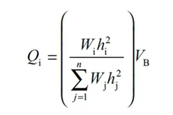
| Lateral Force at Different Levels | |||||||||||||
<!-- [if gte vml 1]>
|
|||||||||||||
| Storey level | Wi | hi | Wihi2 | ki | Lateral Force | ||||||||
| (kN) | (m) | Qx | Qz | ||||||||||
| Roof | 2100 | 26 | 1419600 | 0.17 | 120.28 | 120.28 | |||||||
| 7th | 4100 | 24.5 | 2461025 | 0.29 | 208.51 | 208.51 | |||||||
| 6th | 4100 | 21 | 1808100 | 0.21 | 153.19 | 153.19 | |||||||
| 5th | 4100 | 17.5 | 1255625 | 0.15 | 106.39 | 106.39 | |||||||
| 4th | 4100 | 14 | 803600 | 0.10 | 68.09 | 68.09 | |||||||
| 3rd | 4100 | 10.5 | 452025 | 0.05 | 38.30 | 38.30 | |||||||
| 2nd | 4100 | 7 | 200900 | 0.02 | 17.02 | 17.02 | |||||||
| 1st | 4100 | 3.5 | 50225 | 0.01 | 4.26 | 4.26 | |||||||
| ∑ | 8451100 | 1.00 | 716.0342 | 716.0342 | |||||||||
Design slab element using MS – Excel:
| Design of Slab (IS 456): | |||||||
| Span Shorter Direction (Clear) | ly | = | 5.00 | m | |||
| Span Longer Direction (Clear) | lx | = | 4.00 | m | |||
| Live Load on the Slab | LL | = | 3.00 | kN / m2 | |||
| Compressive stength of concrete | fck | = | 30 | N / mm2 | |||
| Yield strength of steel | fy | = | 415 | N / mm2 | |||
| Unit weight of concrete | Ƴc | = | 25.00 | kN / m3 | |||
| Unit weight of floor finish 100 mm | Ƴ | = | 22.00 | kN / m3 | |||
| Clear concrete cover | = | 25.00 | mm | ||||
| Bearing of slab | B | = | 250.00 | mm | |||
| Cl 24.1 | Span to effective depth ratio | l/d | = | 32 | |||
| Minimum effective depth | d | = | 150.00 | mm | |||
| Overall depth | D | = | 181.00 | mm | |||
| Provide Overall depth | D | = | 150.00 | mm | |||
| Dia of bars for short direction | Φ | = | 12 | mm | |||
| Dia of bars for long direction | Φ | = | 12 | mm | |||
| Effective Depth | d | = | 119.00 | mm | |||
| Loading on the slab | |||||||
| Dead Load of the slab (DL) | 3.75 | kN / m2 | |||||
| Super Dead Load | 4.00 | kN / m2 | |||||
| Live Load on the slab | 3.00 | kN / m2 | |||||
| Total Load on the slab (TL) | 10.75 | kN / m2 | |||||
| Design Load = (Total Load x Load Factor i.e. 1.5) | 16.13 | kN / m2 | |||||
| Effective Span | lx | = | 5.12 | m | |||
| ly | = | 4.12 | m | ||||
| Ratio | ly/lx | = | 0.805 | Two Way | |||
| T26/27 | |||||||
| 1.0 | ax | 1.10 | ay | ||||
| For negative moments (at top) | 0.047 | 0.035279 | 0.053 | 0.047 | |||
| For positive moments (at bottom) | 0.035 | 0.025232 | 0.04 | 0.035 | |||
| BM per unit width of slab | Mx = ax w lx2 | My = ay w lx2 | |||||
| For negative moments (at top) | 14.91 | 19.86 | KN-m/m | ||||
| For positive moments (at bottom) | 10.66 | 14.79 | KN-m/m | ||||
| Shear force , V | 0.5wlx | 41.27 | kN/m | ||||
| To check the effective depth of slab | |||||||
| Mu,lim | = | 0.138fckbd2 | |||||
| d | = | 60.01 | mm | ||||
| Depth of slab for shear force | |||||||
| T20 | τc,max | = | 3.5 | N/mm2 | |||
| τc | = | 0.29 | |||||
| Cl 40.2.1 | k | = | 1.3 | D=150mm | |||
| τc | = | 0.377 | N/mm2 | ||||
| τv | = | Vu / bd | |||||
| = | 0.35 | N/mm2 | |||||
| τv | < τc | < τc,max | |||||
| 0.35 | 0.38 | 3.5 | |||||
| SAFE | |||||||
| Determination of areas of steel | |||||||
| Mu = | 0.87fyAstd(1-Astfy/fckbd) | ||||||
| For Negative moments | Mu Top | = | 14.91 | ||||
| Ast | = | 434.56 | mm2/m | ||||
| For Positive moments | Mu Bot | = | 10.66 | ||||
| Ast | = | 310.81 | mm2/m | ||||
| Determination of distribution steel | |||||||
| Astmin | = | 0.12bd | |||||
| 142.8 | mm2 | ||||||
| Selection of reinforcing bars | |||||||
| Area of bars (Top steel) | = | 113.04 | mm2 | ||||
| Spacing | = | 260 | |||||
| = | 240 | mm | |||||
| Provide 12mm bars at a spacing 240mm | |||||||
| Area of bars (Bottom steel) | = | 113.04 | mm2 | ||||
| Spacing | = | 364 | |||||
| = | 300 | mm | |||||
| Provide 12mm bars at a spacing 300mm | |||||||
Create structural model using STAAD Pro Connect Edition:
- Open STAAD Pro software and first we need to create a frame layout
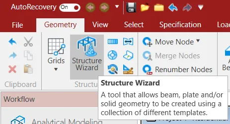
- Select structural wizard option
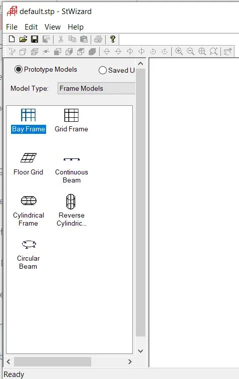
- Change the model type in 'Frame models' then select the Bay frame option
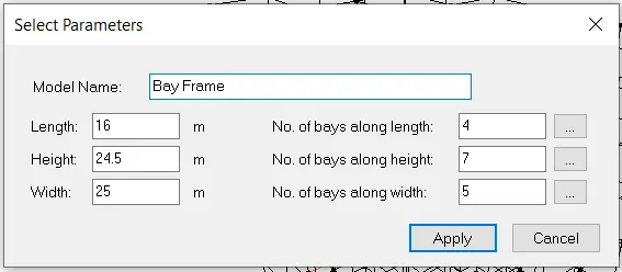
- The selected parameter dialog box is appeared now define the parameters as what we want and click apply
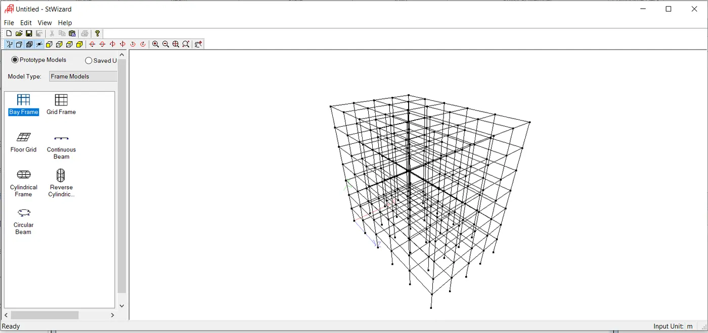
- Then merge in to STAAD model and also create a roof in normal method
- Now create the beam properties and materials
- The same procedure to follow the create the column properties and materials
- Now assign to the columns and beams using select option in parallel Y
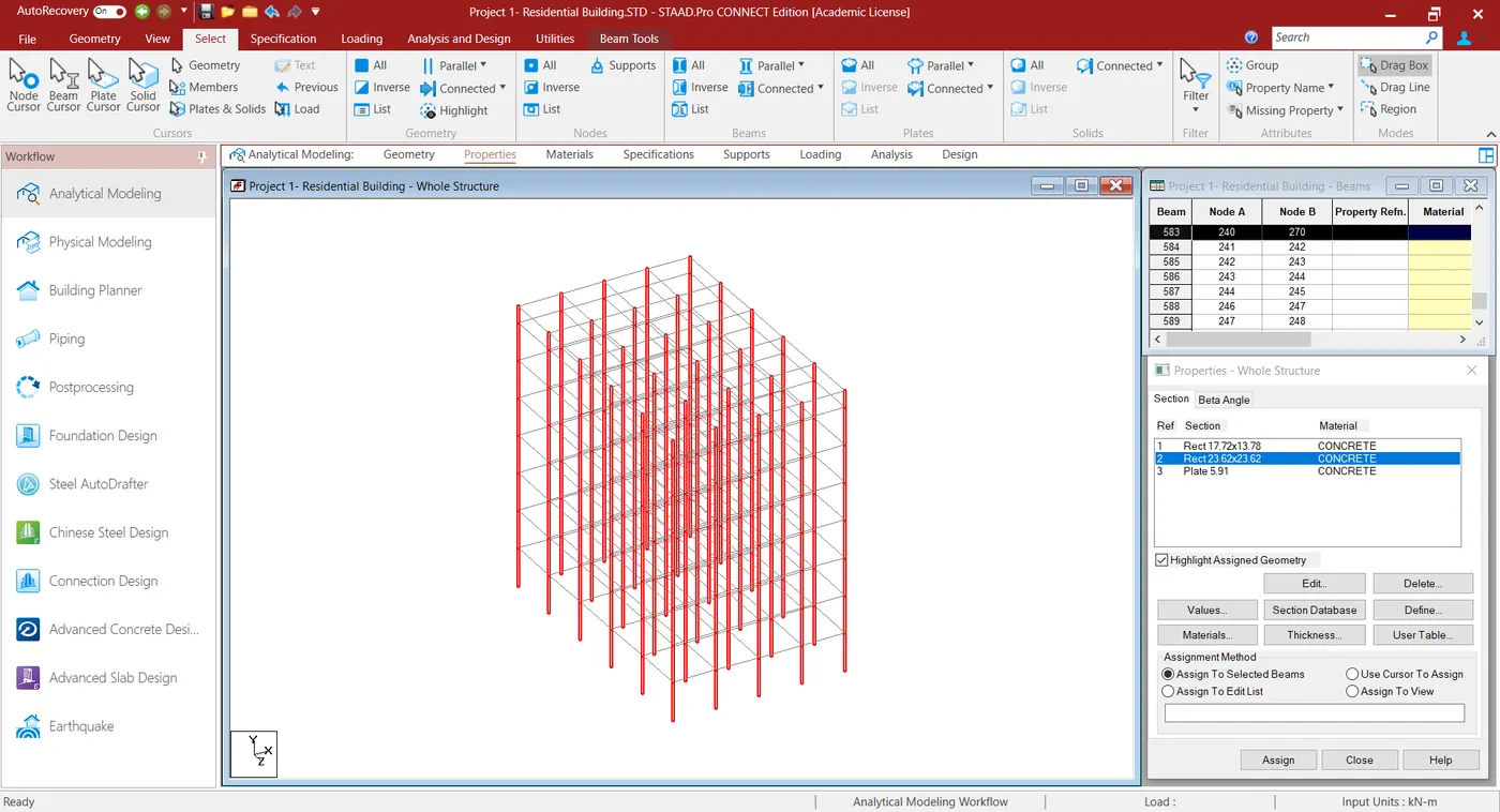
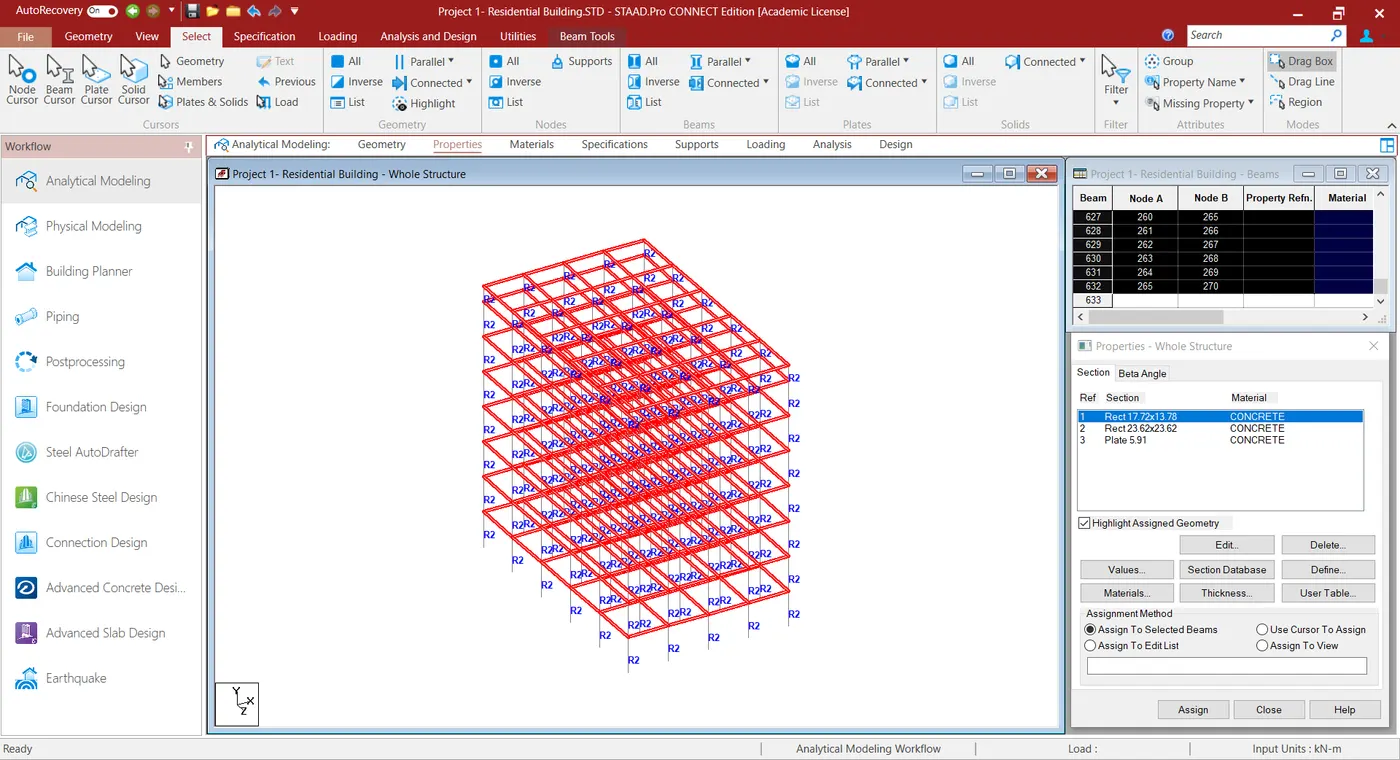
- The beams have been assigned to the selected parallel X and Z asssign to it
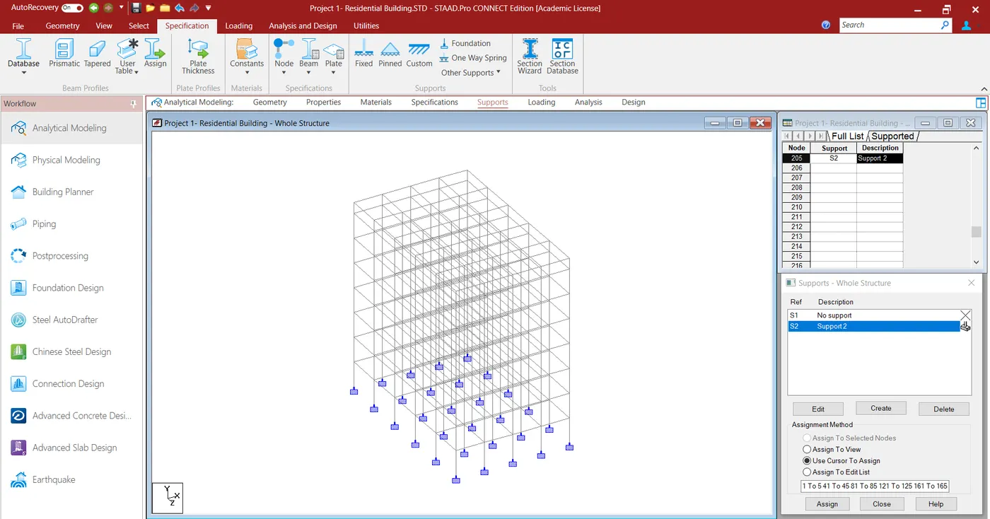
- Create a support select fixed support option
- Add seismic load, so first loading tab and click new option, the dialog box will be appeared
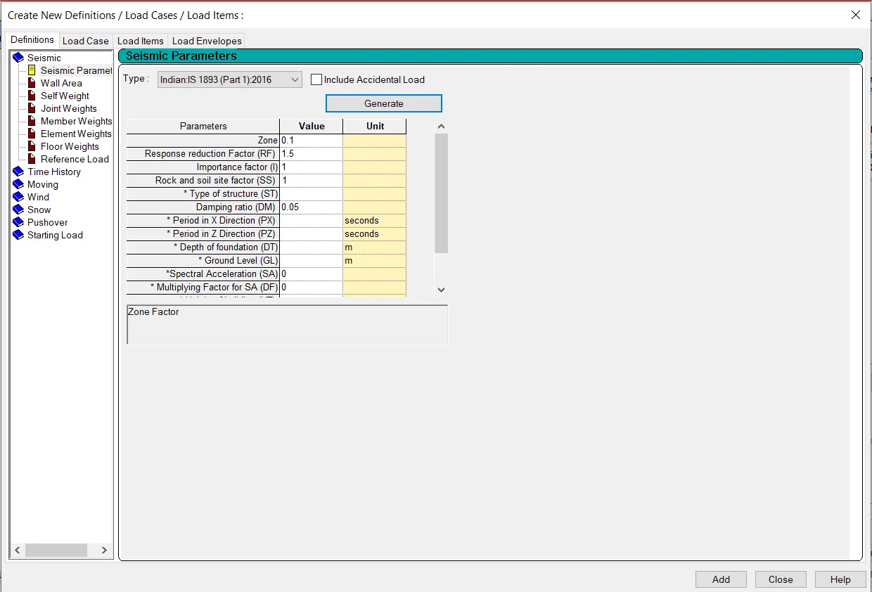
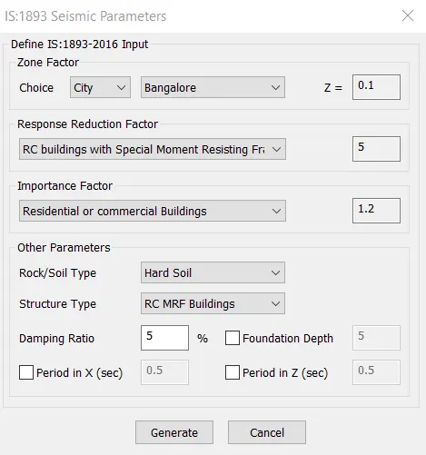
- Click generate option the seismic parameter dialog box is appeared and fill the details were given
- Next add the seismic self weight
- Now select the Wind definition option and click add button, give the name and click add.
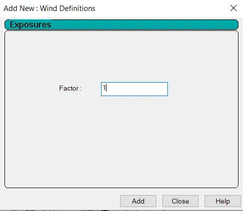
- Add wind exposures
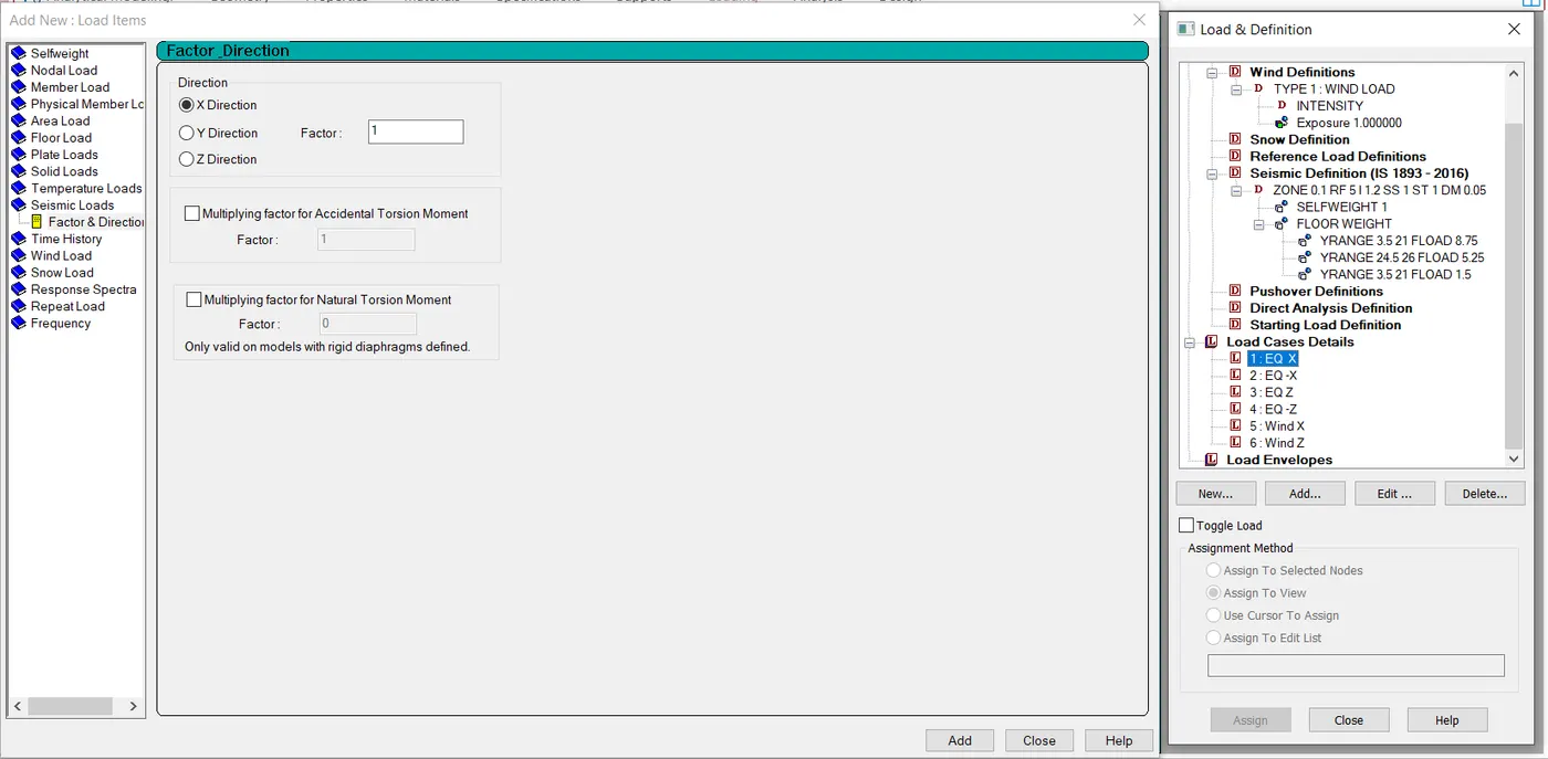
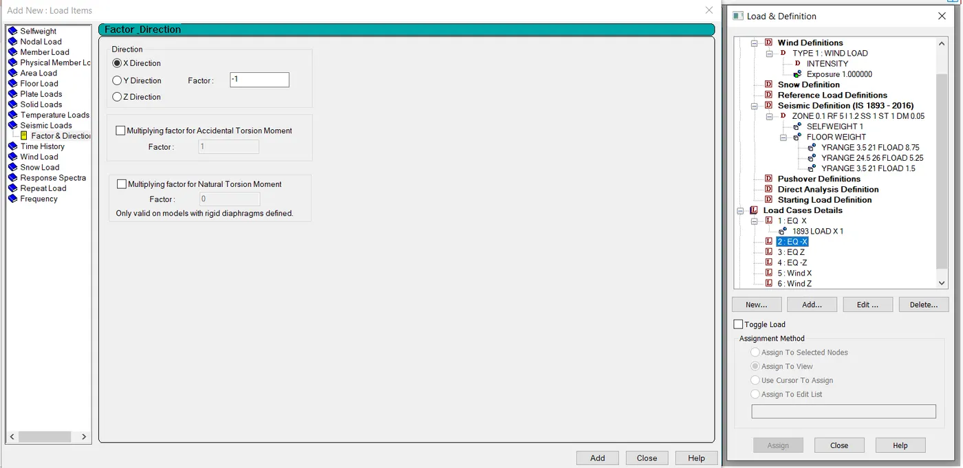
- Now craete load case details, add the Earthquake load in the X and -X direction
- Now add the earthquake load in Z and -Z direction
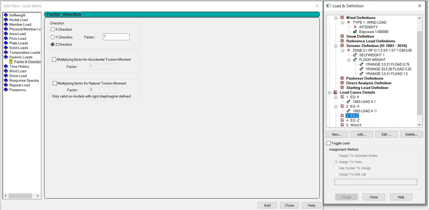
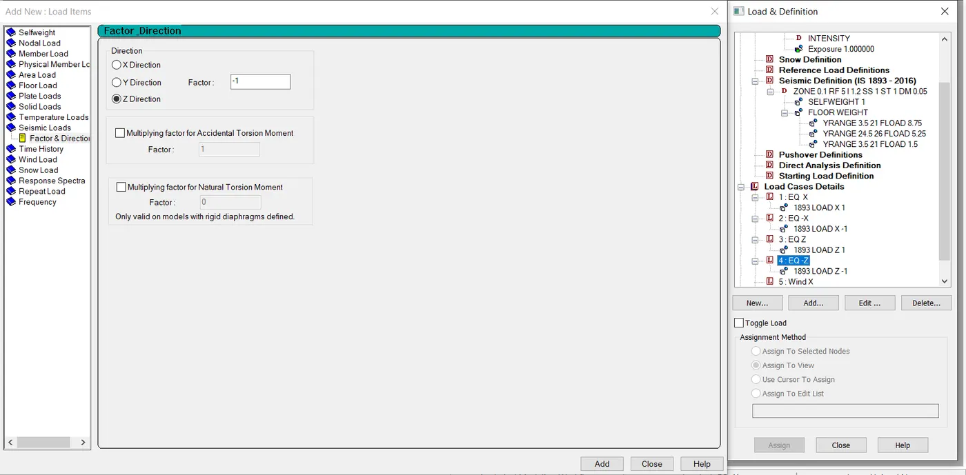
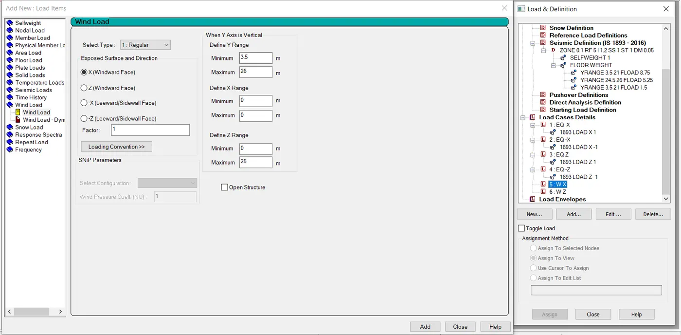
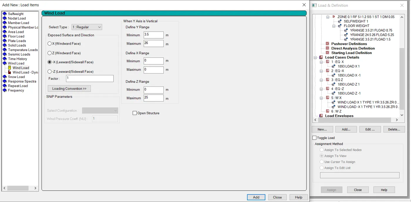
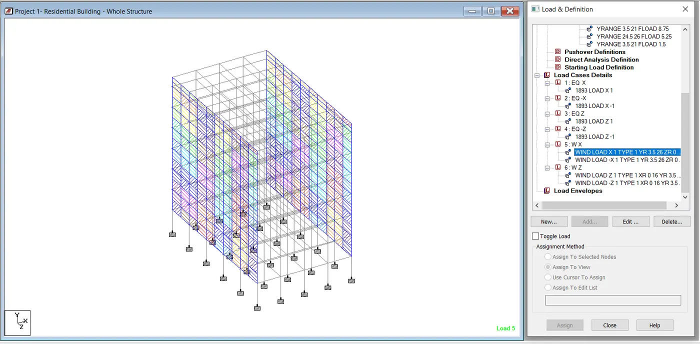
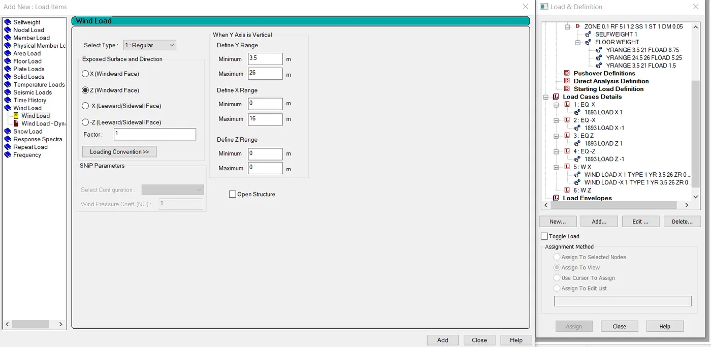
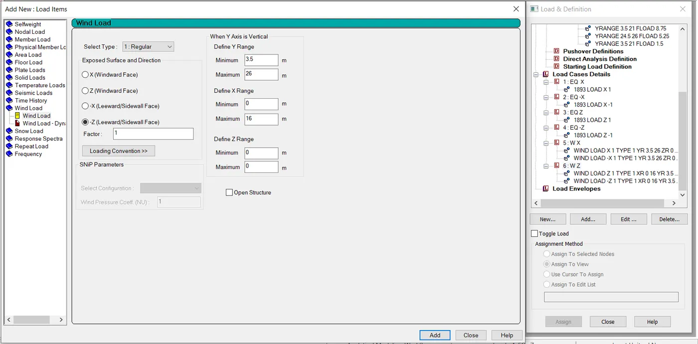
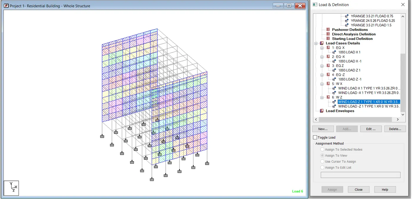
- Add the wind case in X and Z direction
X - Windward
-X - Leeward
Z - windward
-Z - Leeward
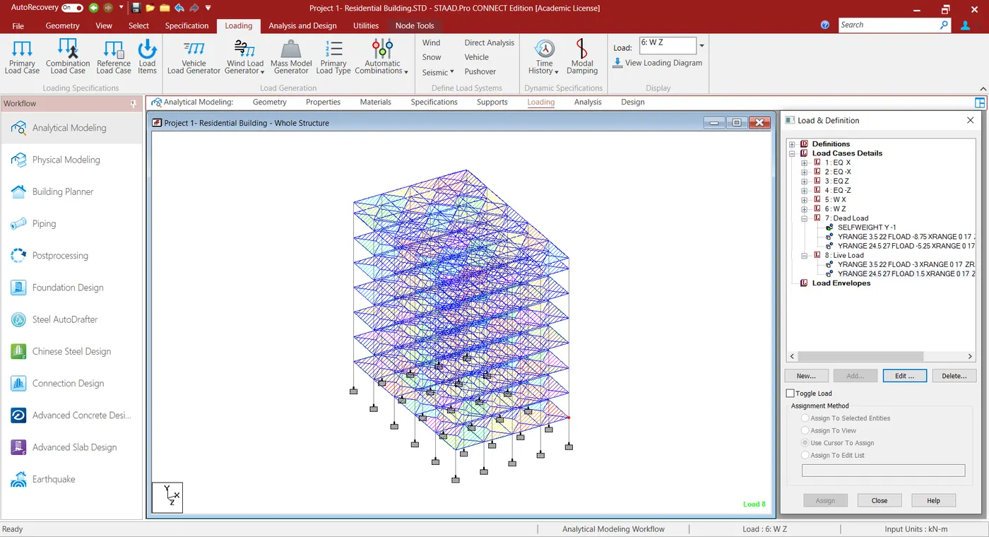
- Now define the dead load and live load. Click load case details and select add option to add dead load, live load. first assign the selfweight in dead load. Then assign the dead load of floor
- Now assign the dead load of roof
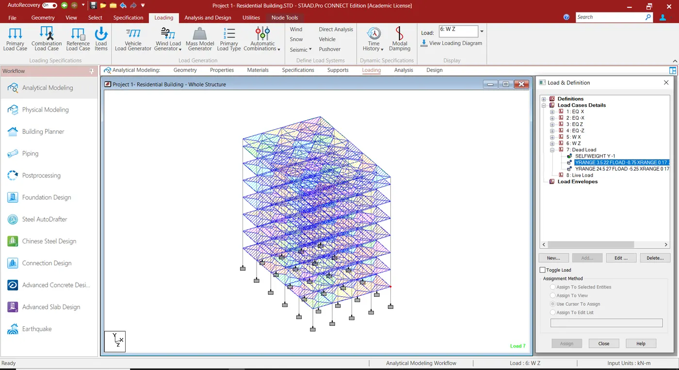
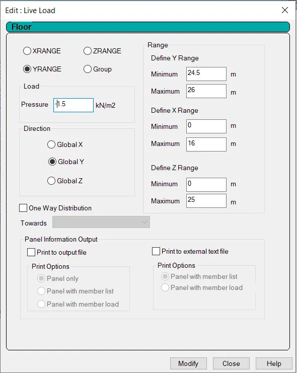
- Now assign the Live load on floor
- Then Live load on roof
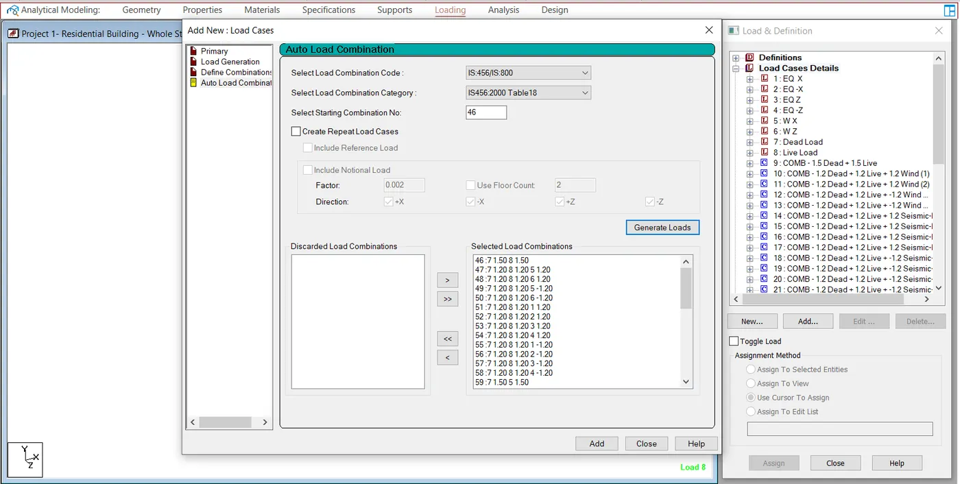
- Now Add load combination and select Auto load combination option
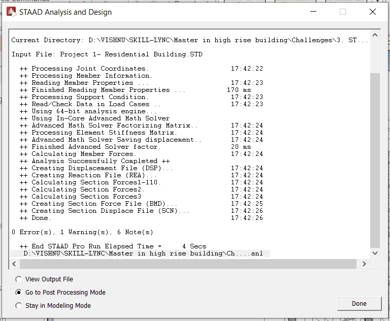
- Here now all the loads has been applied successfully, noe run the analysis
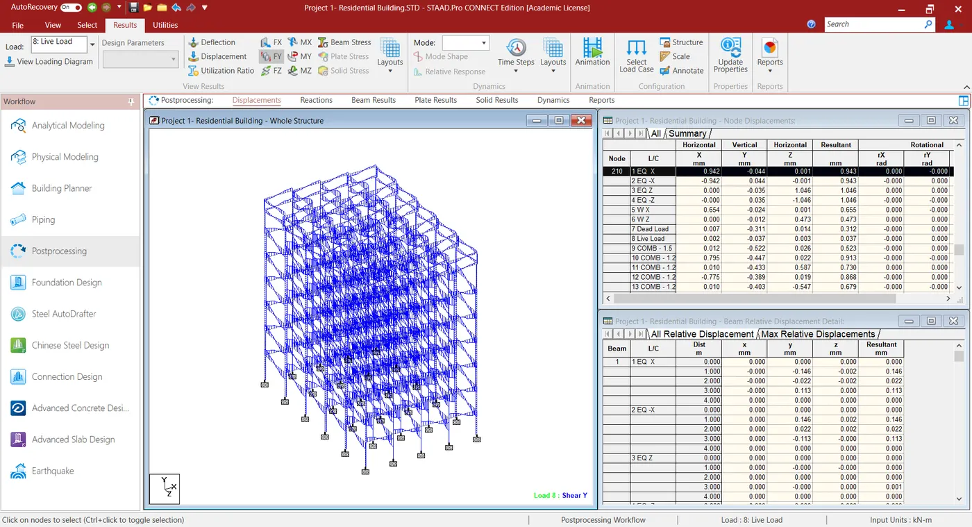
- Shear Force
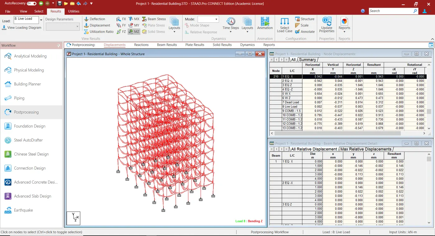
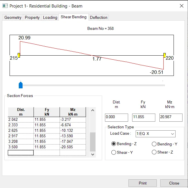
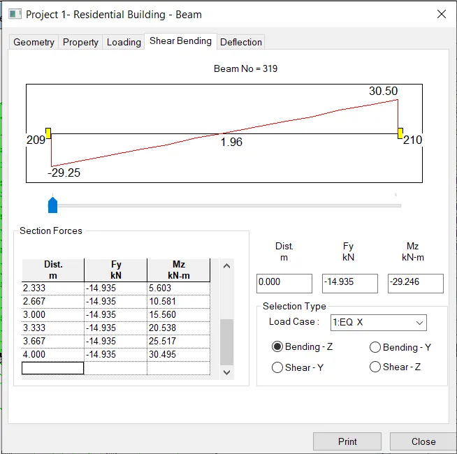
- Bending moment
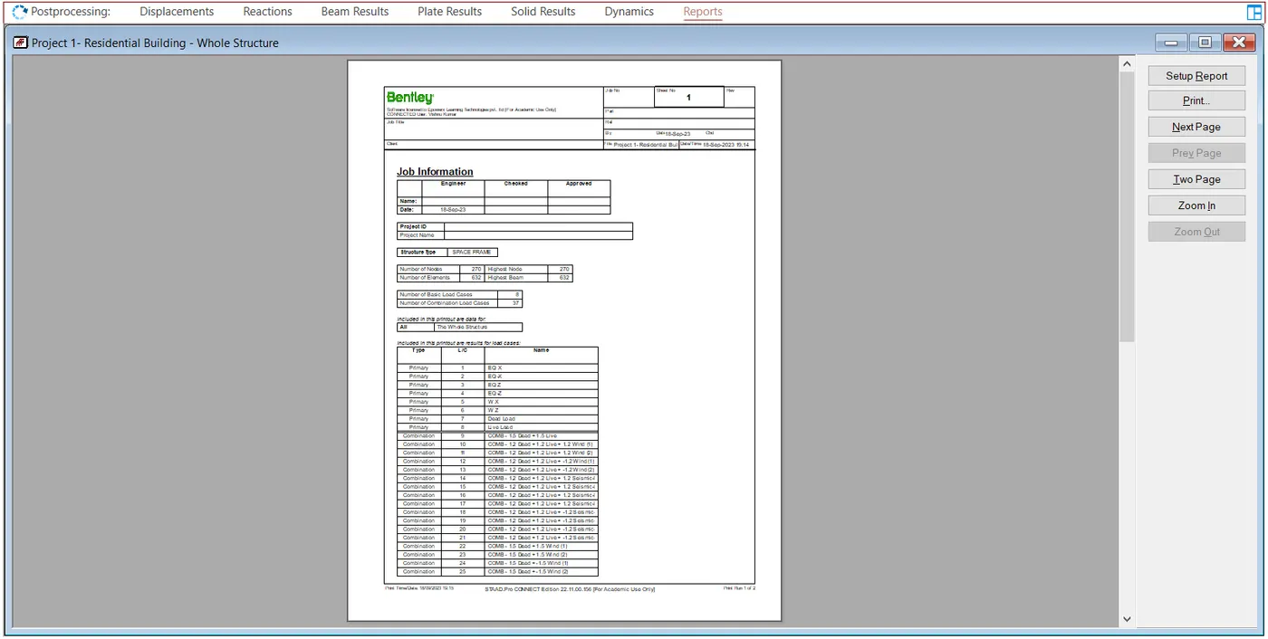
- Click the Report tab
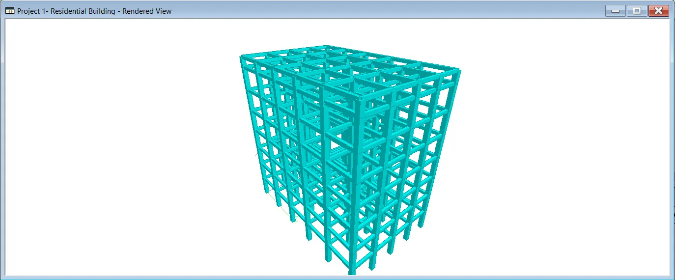
- Right click on the mouse there is 3D rendering option and click that
Design beam and column element using STAAD RCDC:
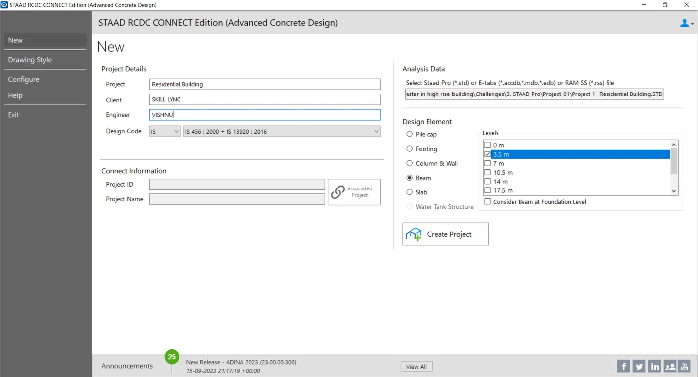
- In the STAAD Pro model there is a option called RCDC to design the beam and column. Create a new project and fill the detail
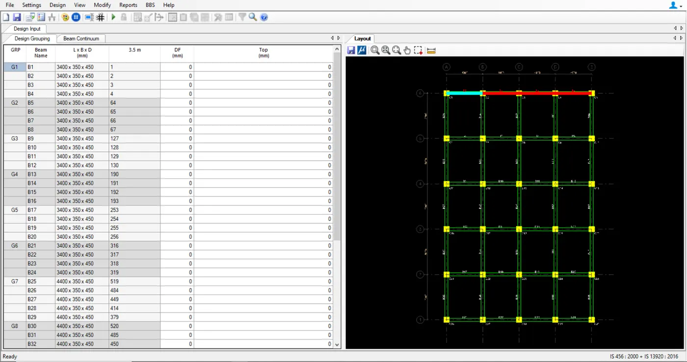
- After creating new project the beam details as shown
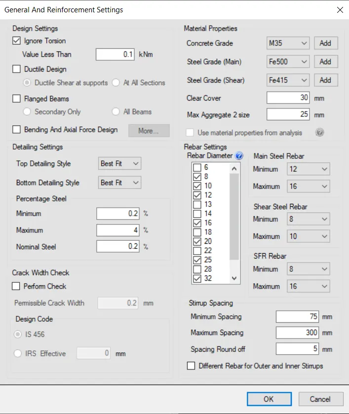
- Go to setting tab > click General and Reinforcement and fill the data
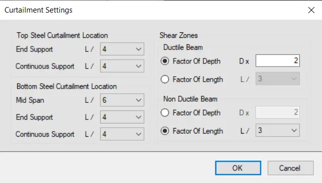
- Again go to setting tab > Rebar curtailment
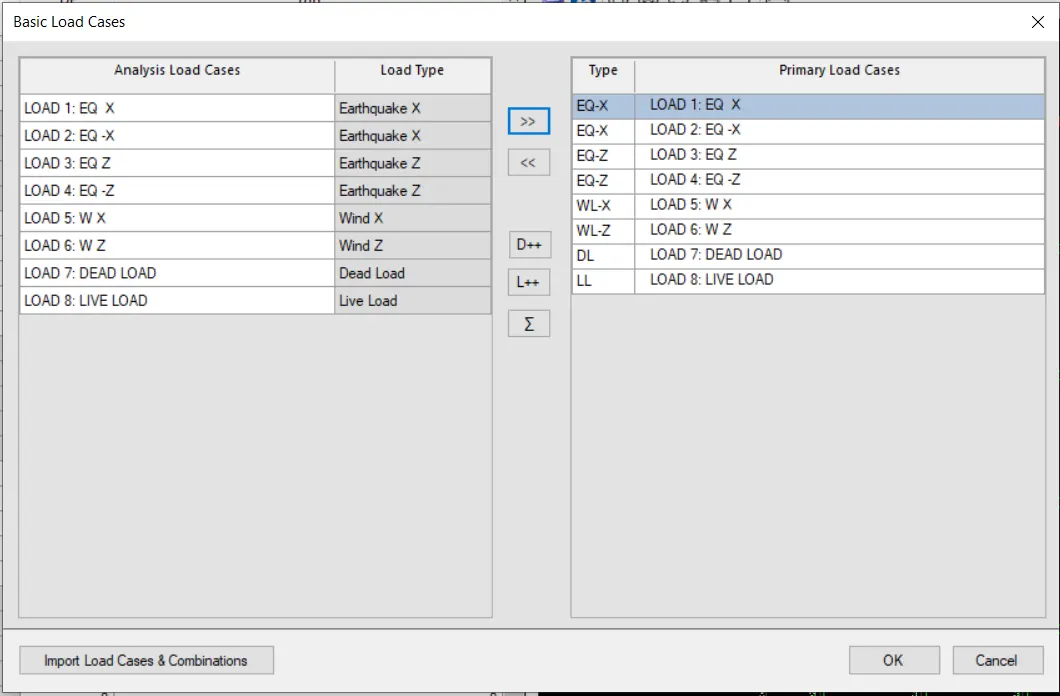
- Now acquire the load combination
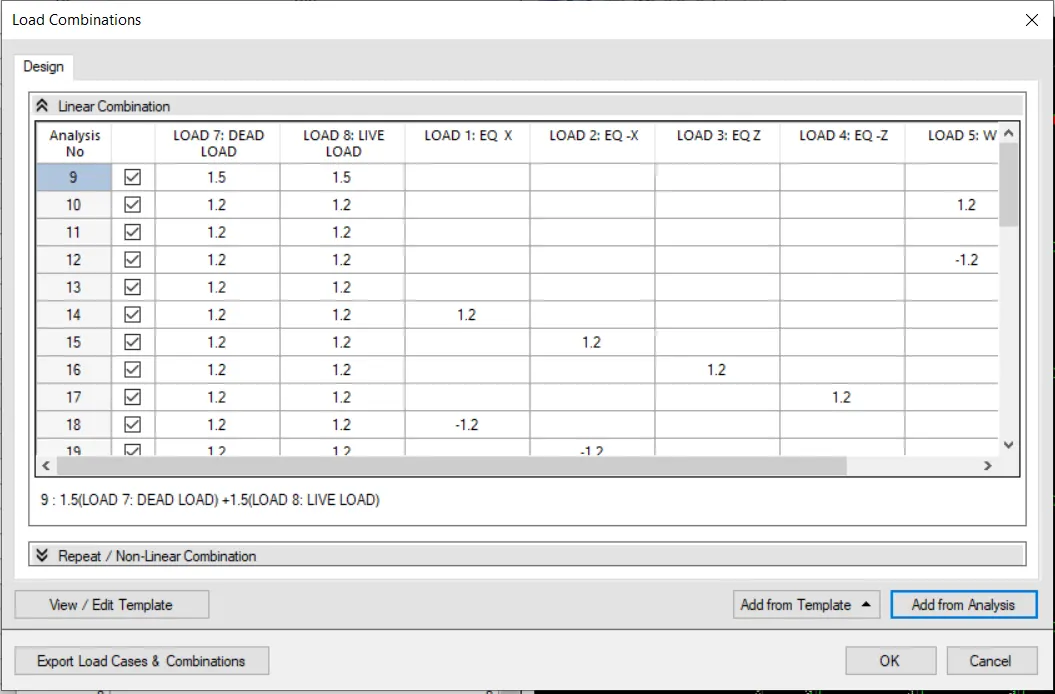
- Import the load combination
- Go to design tab > click Auto design option
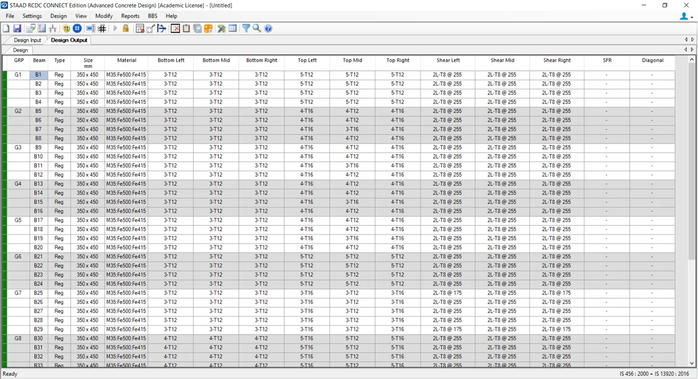
- Now check the failure diagnostics, go to Reports tab > Failure diagnostics
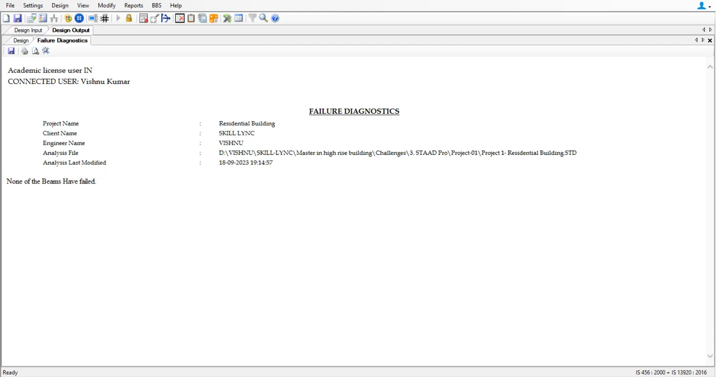
- None of the beams have failed
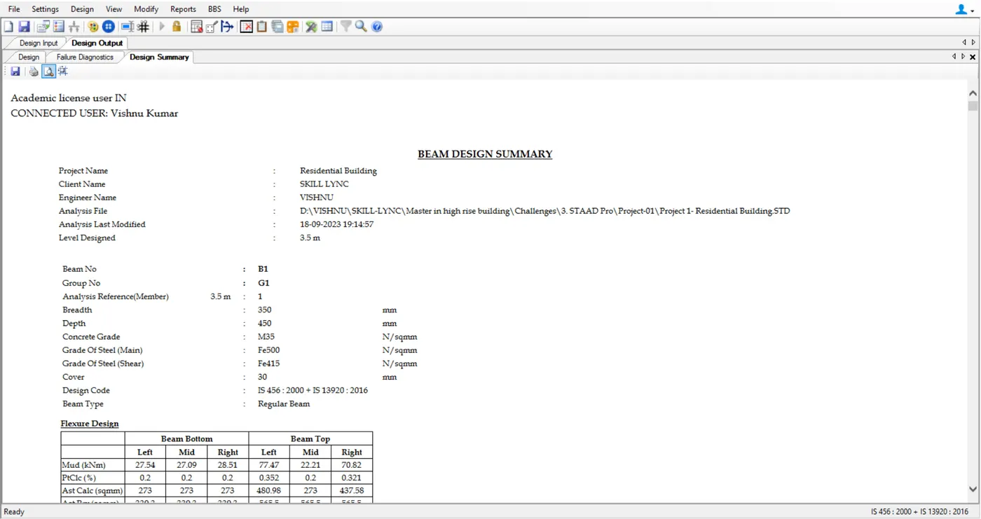
- Next click Repots > design summary
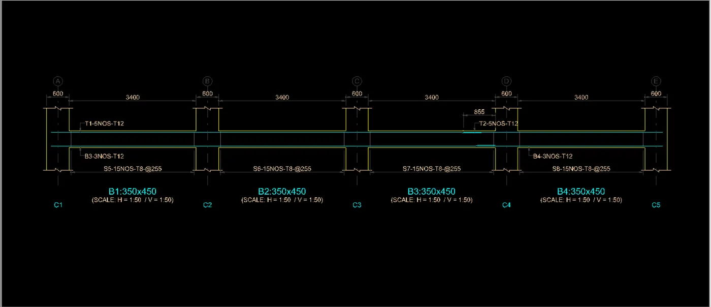
- Go to Report > Elevation
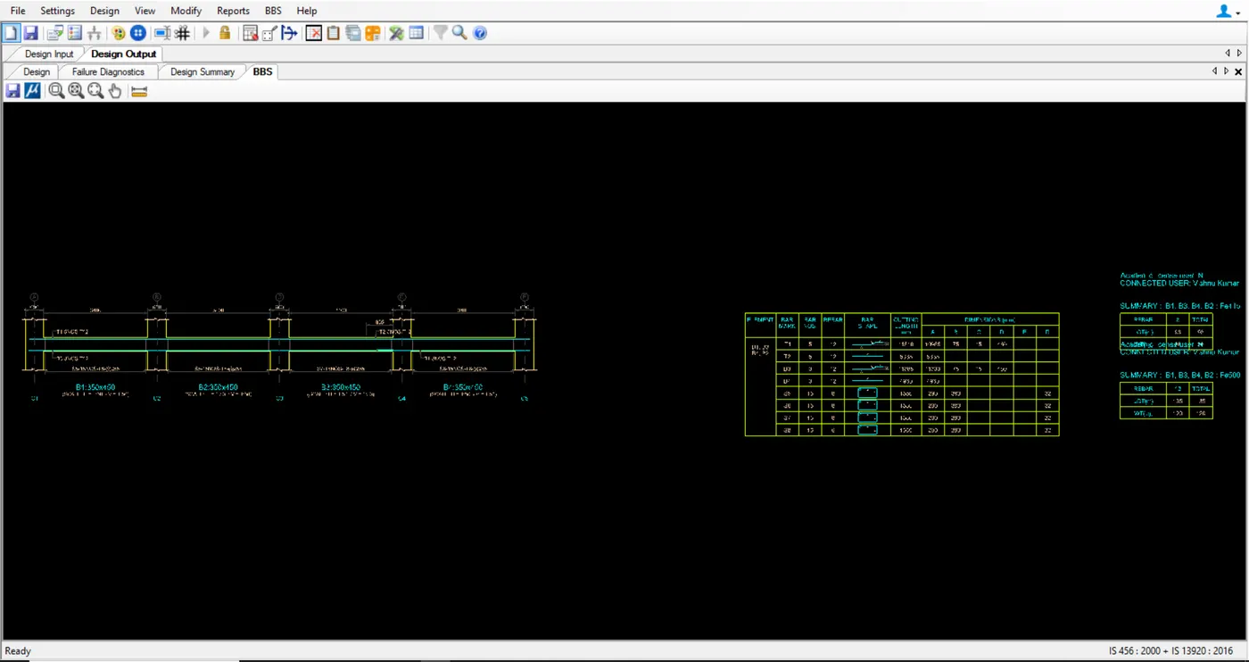
- And now we going to design the column
- Create the new project
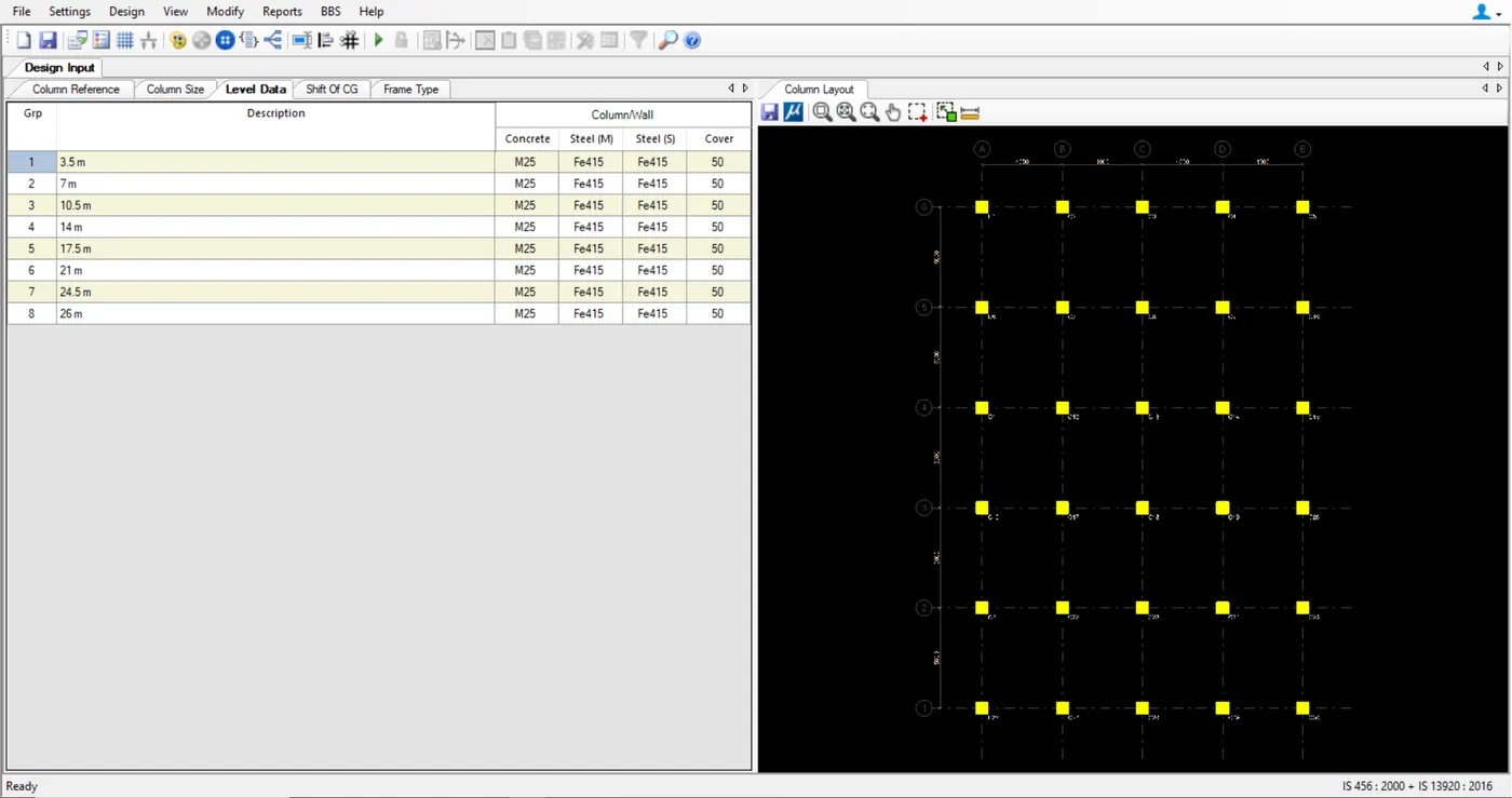
- go to setting > General and Reinforcement

- Now acquire the load combination
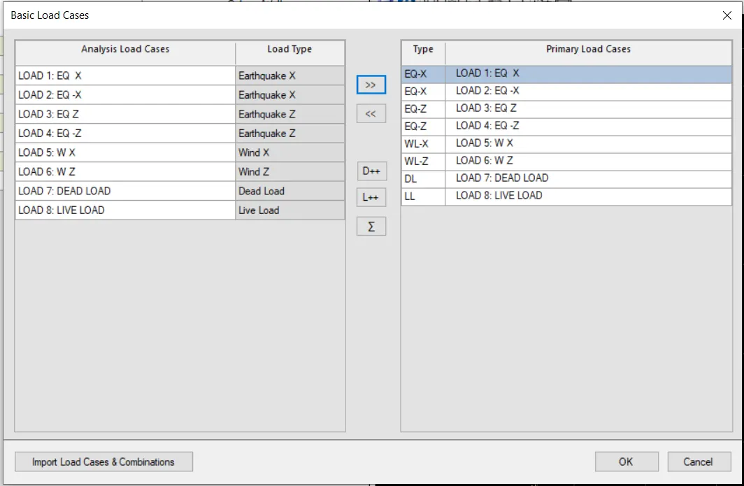
- Import that load combination
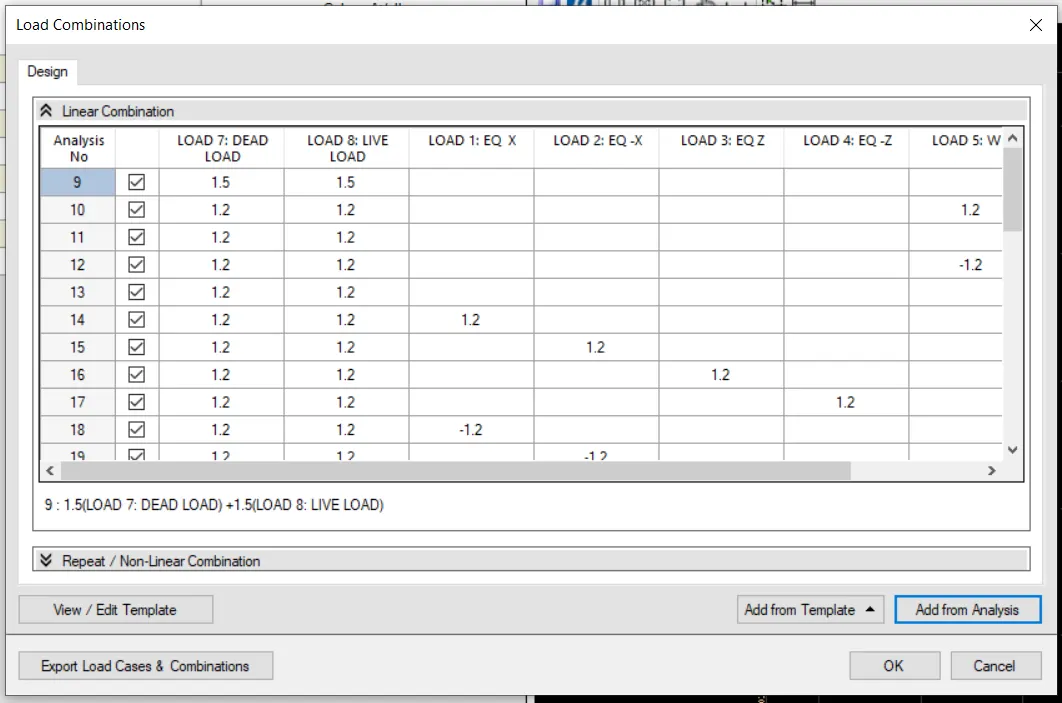
- Now check the failur diagnostics click Reports > Failure diagnostics
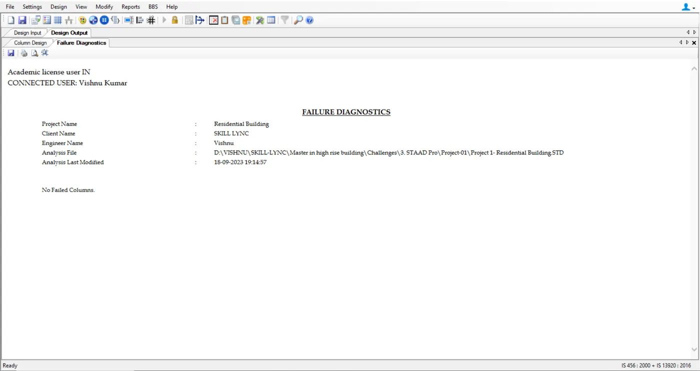
- There is No failed columns
- Go to report > Elevation option
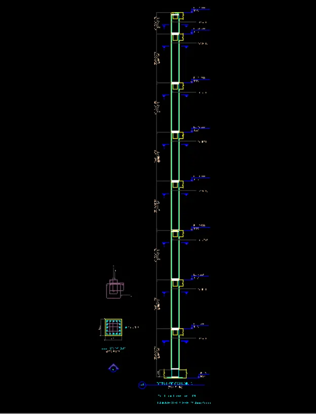
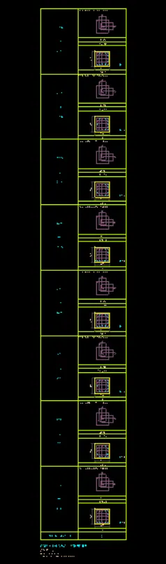
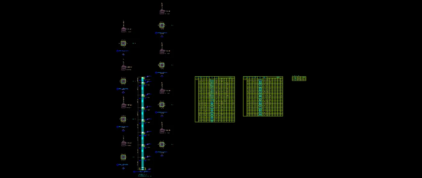
- Go to report tab > Design summary
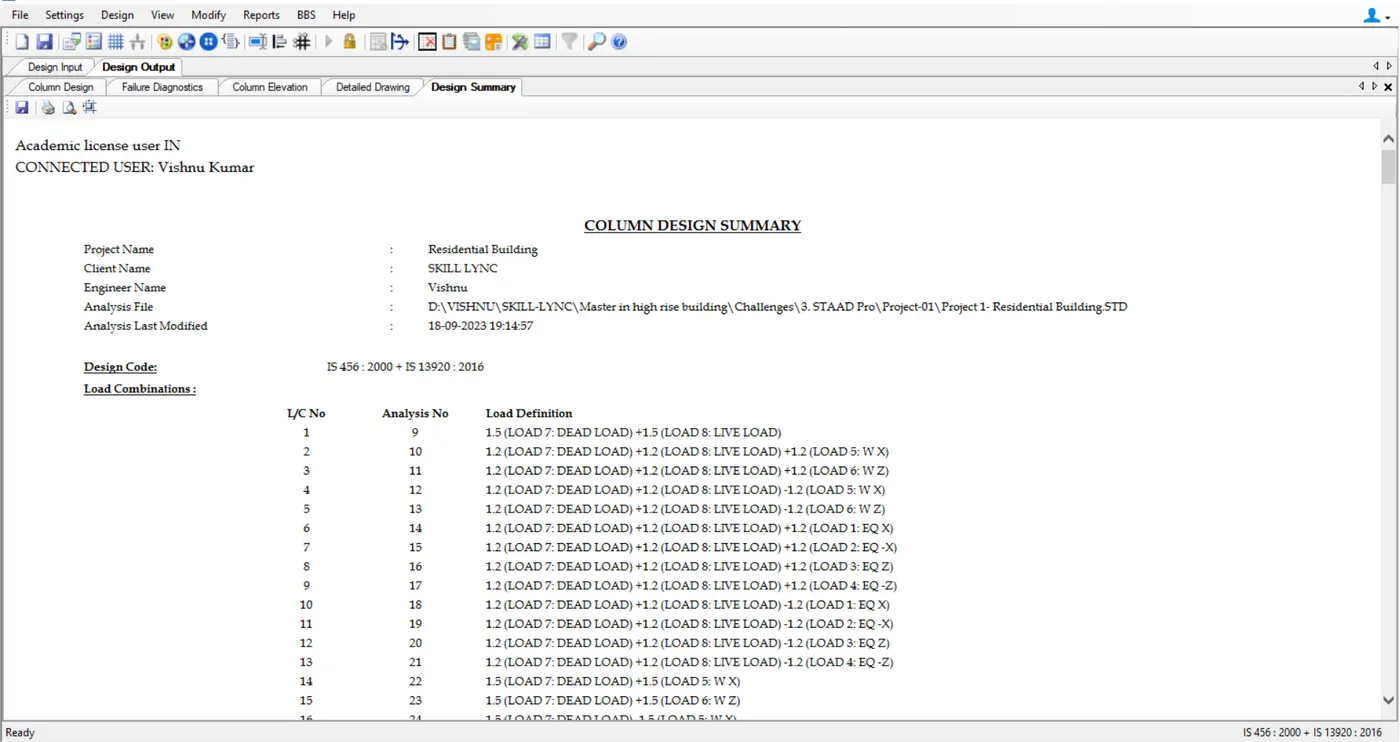
Design Foundations using STAAD Foundation:
- In STAAD Pro model there is a Foundation design option
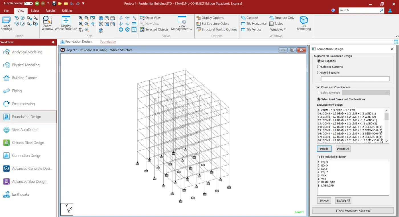
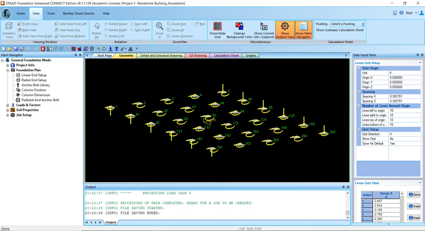
- Click STAAD foundation advanced
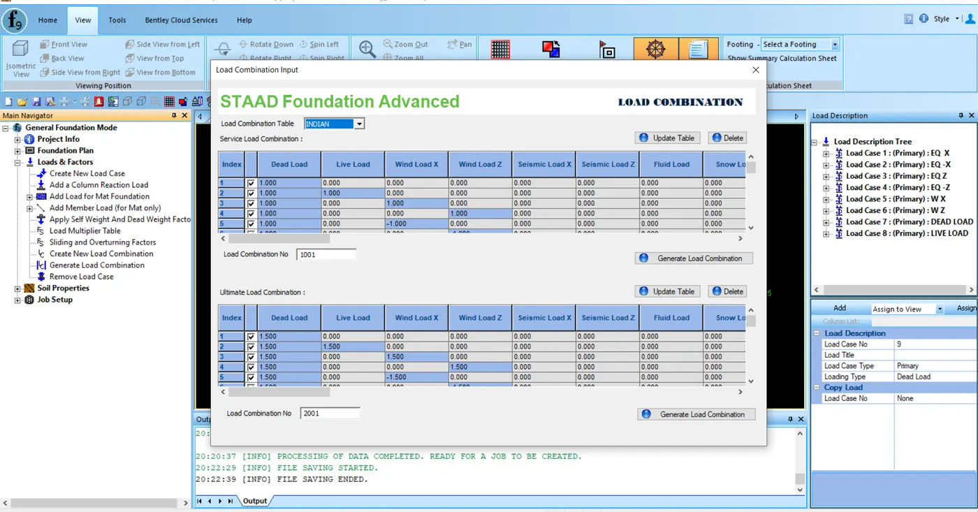
- Generate the load combination
- Create the job information
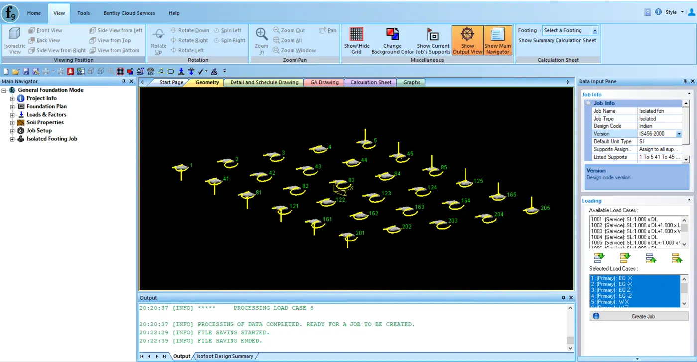
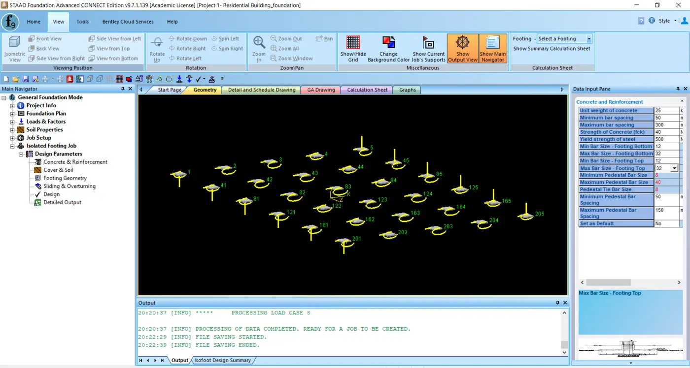
- Concrete and Reinforcement
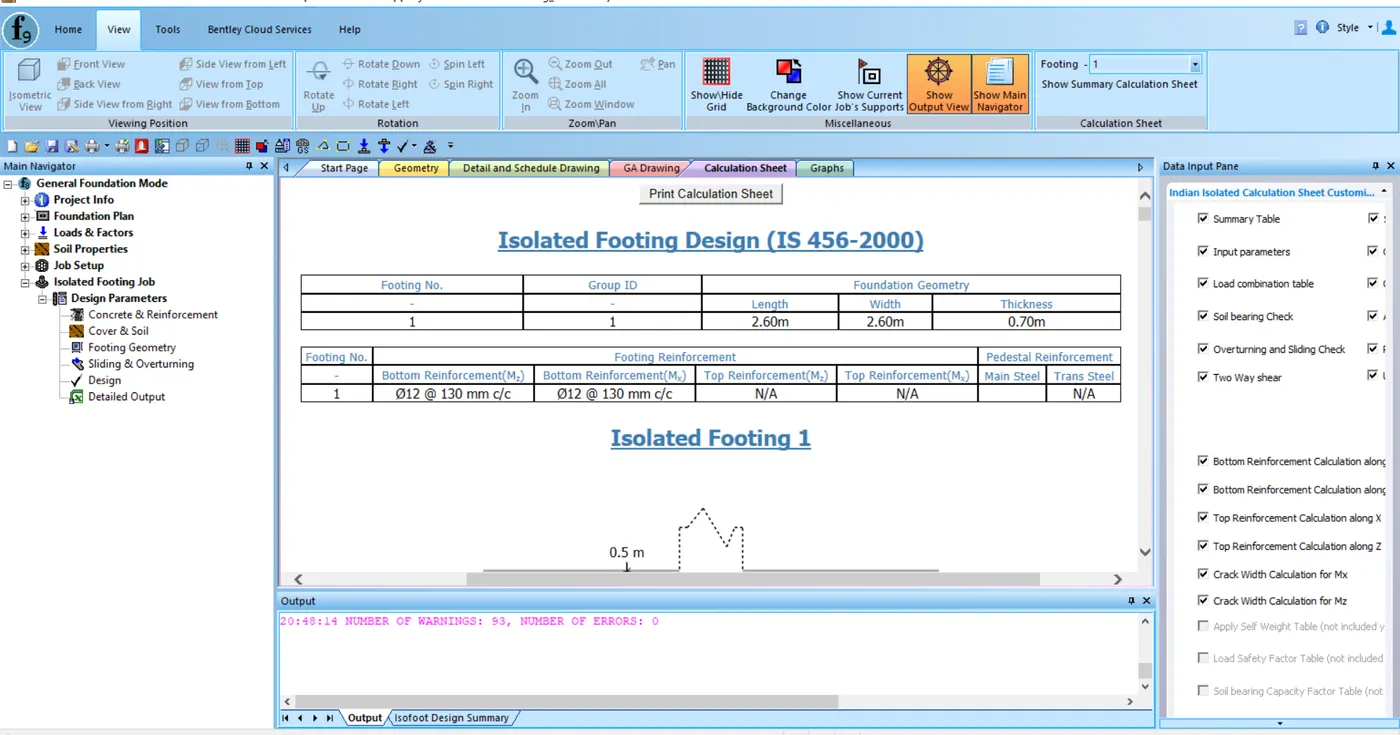
- Isolated Footing design
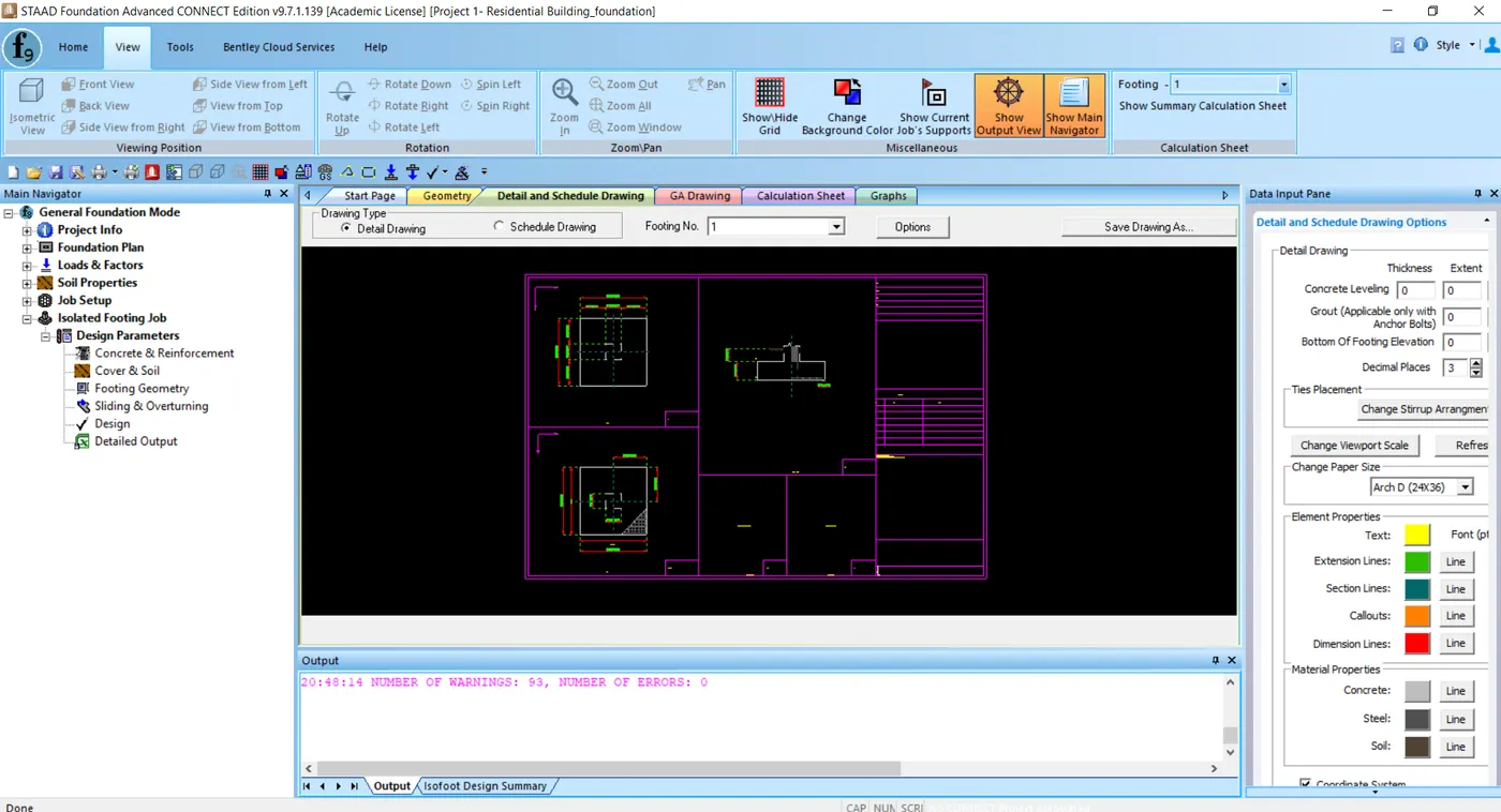
- Detail ans Schedule drawing
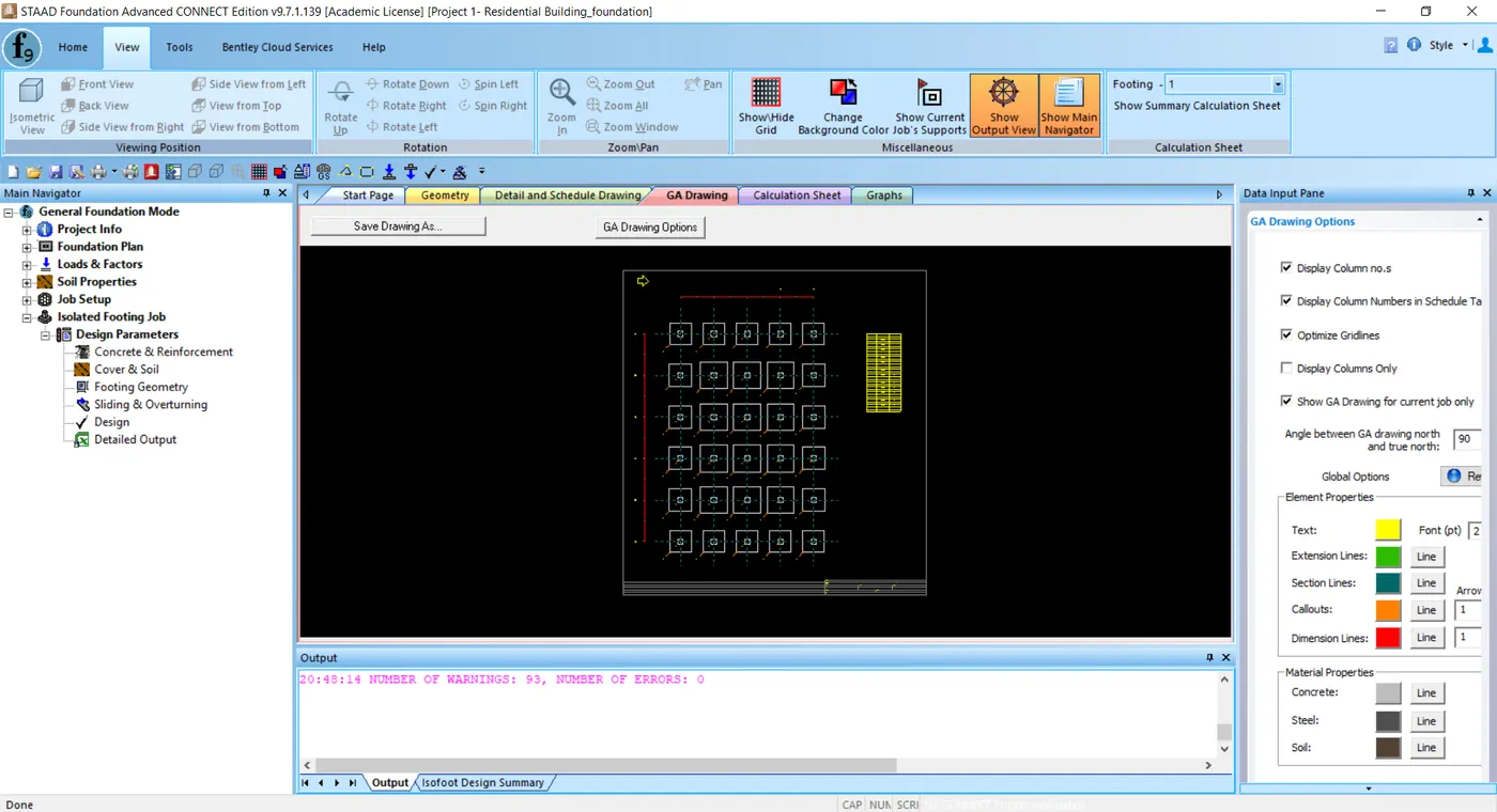
- GA drawing
Prepare bar bending schedule for beam and column using STAAD RCDC:
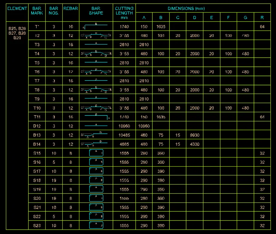
Bar Bending Schedule for Beam:
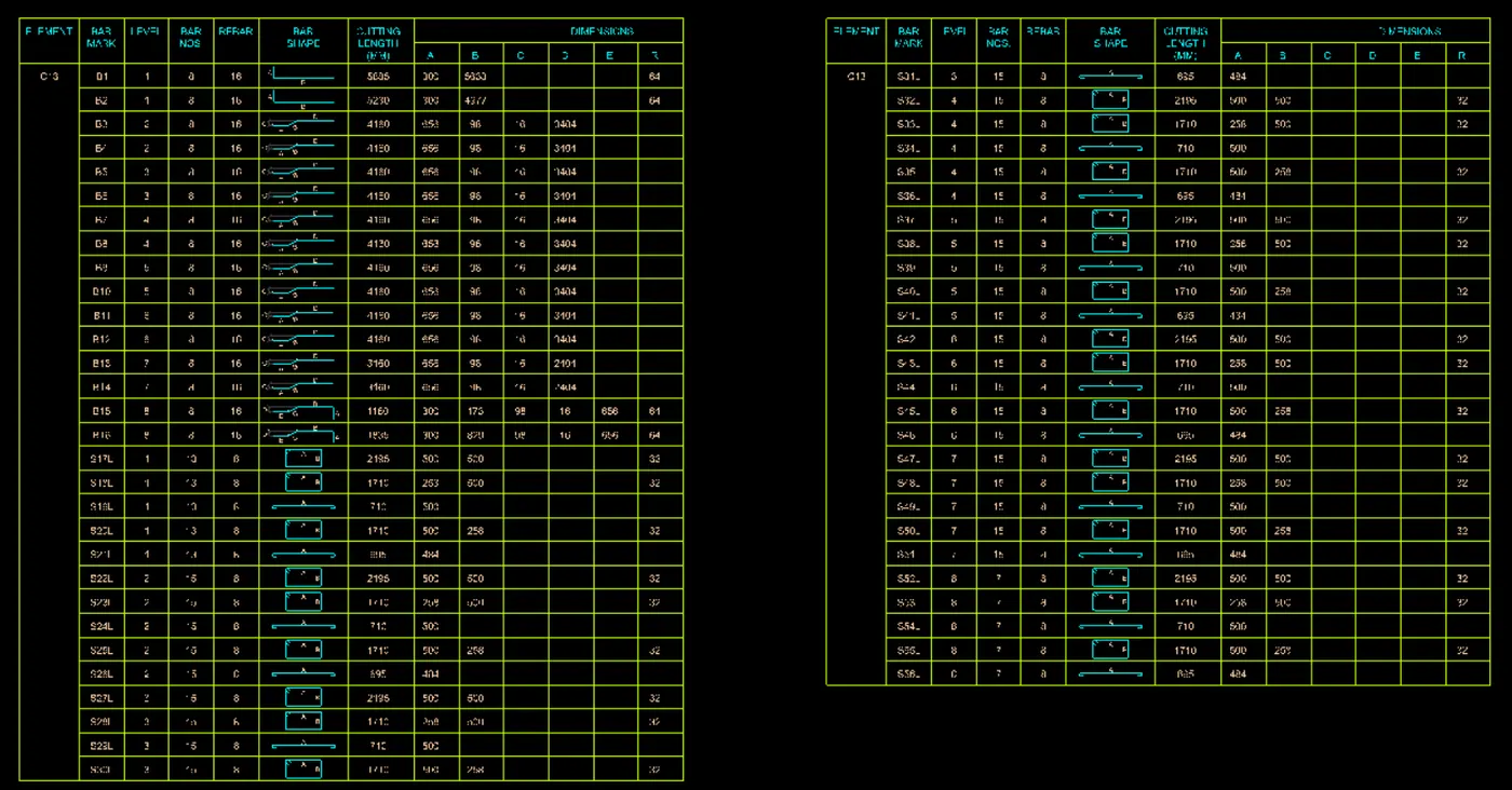
Bar Bending Schedule for Column:
RESULT:
Hence the beams and columns are designed using RCDC, Foundation are designed using STAAD foundation, all the tasks are successfully performed and necessary files are attached.