Project 1
PROJECT 1:
WIRING HARNESS DESIGN IN VIRTUAL INTERFACE:
AIM:
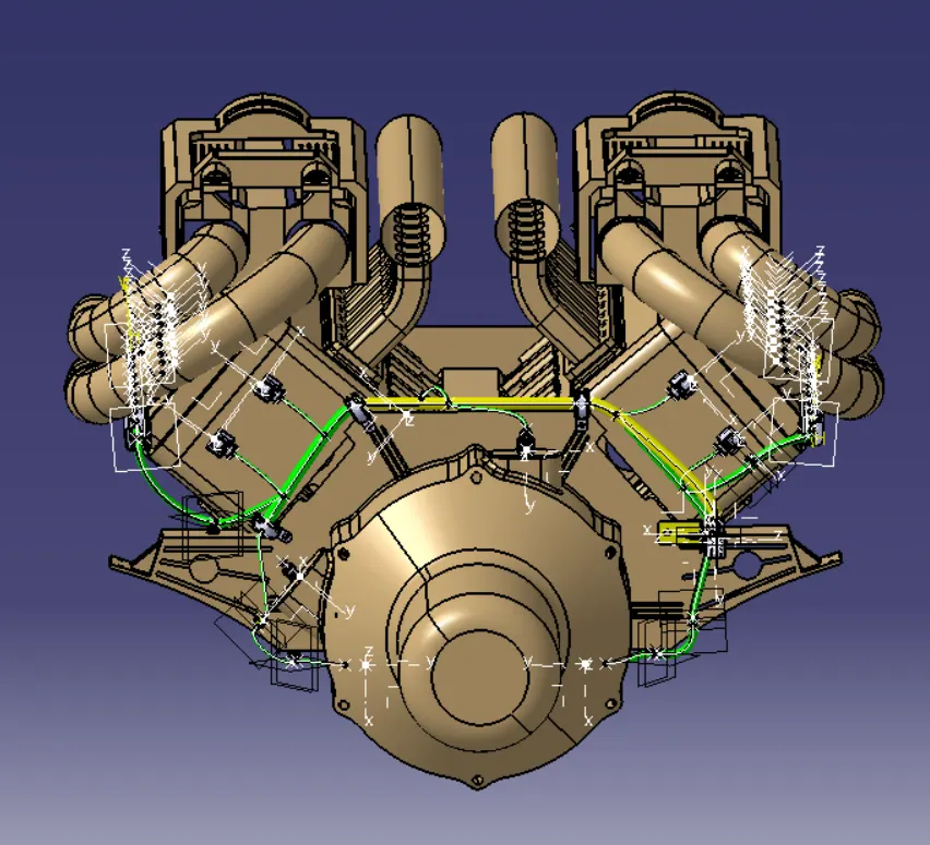
- We need to create routing design to given 16 Valve engine assembly.Here we need to consider basic and industrial standard routing creteria like packaging rules,protection covering,defining electromechanical components,standard clearance,clip/clamp selection,bundle continuty and etc...
INTRODUCTION:
- In this challenge we are going to apply all Industry best practices studied in this course shall be demonstrated in design.
- Here we need to follow the wiring harness design process.
1.INPUT COLLECTION:
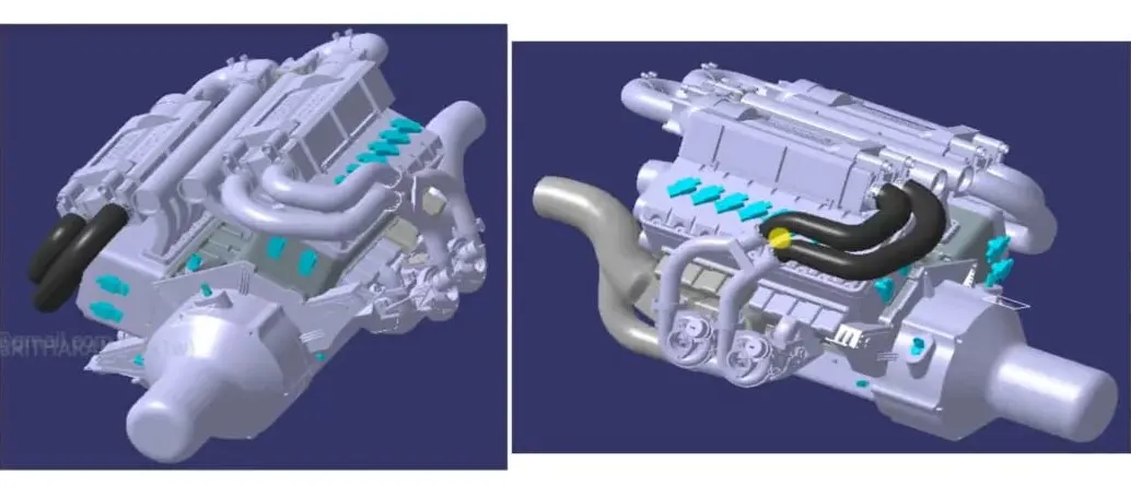
- First we need to get vehicle relavent 3D Data E&E logical component 3D Data and its specification from Engine developement CAE team.
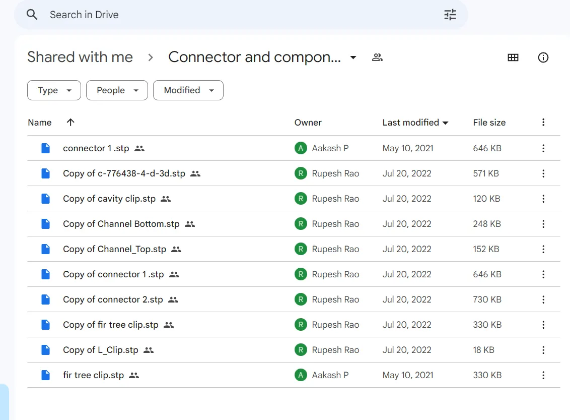
- Here they are given google drive link to downlode the CAD Data and E&E components for 16v Engine Aseembly,from that we are downlode the required data.
2.COMPONENT IDENTIFICATION:
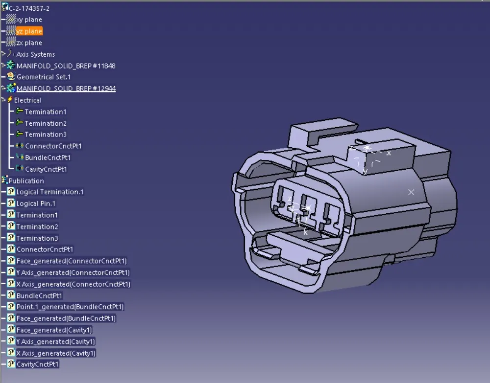
- Then downlode the E&E components and create library for that,save in the desire location.
- If the components are not define we should define the components electrically.

3.HARNESS TOPOLOGY:
- It is a process that strategy to divide or split the harness between different pieces to achieve best manufacturability,serviceability and cost effective design.
- This stage is the starting ideation phase that how to create the routing? and what types of sensors we had? for that what type of connector we are going to use ? so,for those questions clear in this area.
- In 16 Valve assembly we are had Fuel injection system,Engine oil pressure sensors,neutral precision sensor,vehicle speed measuring sensors,and cam shaft sensor.
- For those things we need to select connectors or otherwise the sensor manufactures finalise that sensors.
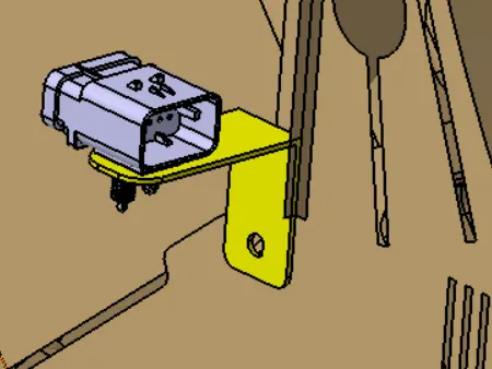
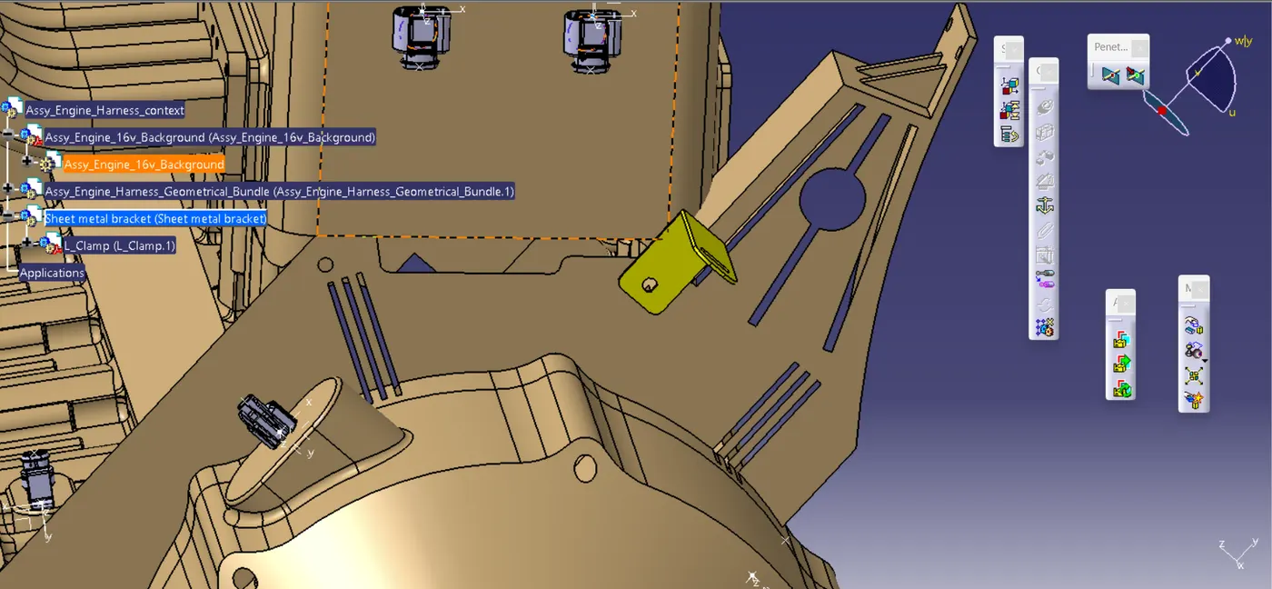
- Then we need to decide inter connecting connection and start the routing from that area,here we place that connector near right side of the engine area.
- for that we need to create L-clamp for holding that connector.
- In fuel injection system area we are going to use chanel for protecting and guiding the harness routing.
- After that we need to review our selections and routing methode with senior engineers and get agreement with them.
4.CONCEPT ROUTING & PACKAGING PROPOSAL:
- After review agreement we need to design the concept routing & packaging proposals during this time we need to decide what types of clips/clamps we are going to use during the routing only.
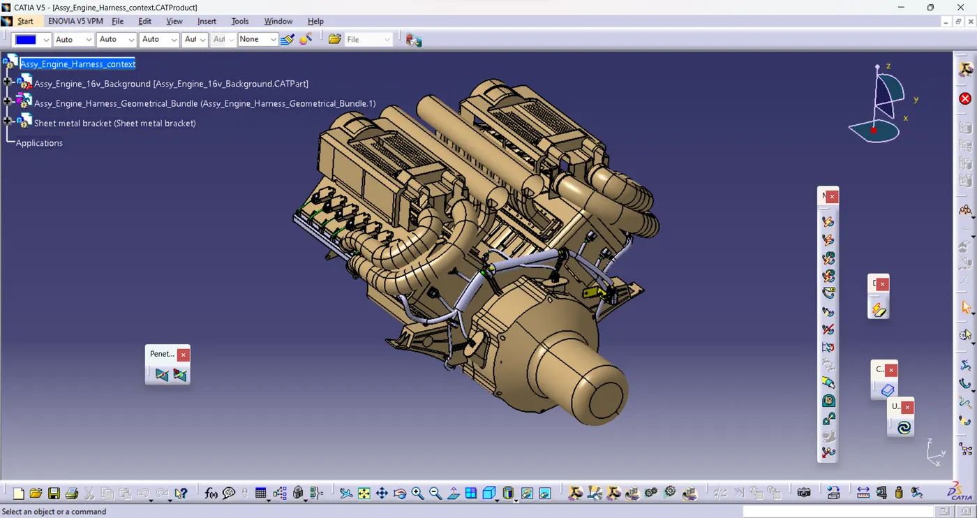
- For that we need to open the catia and create the harness assembly context,in that we need import the 16V Engine assembly,and then we need to create the geometrical bundle.
- In that we need to import a connectors which we want inside the assembly.
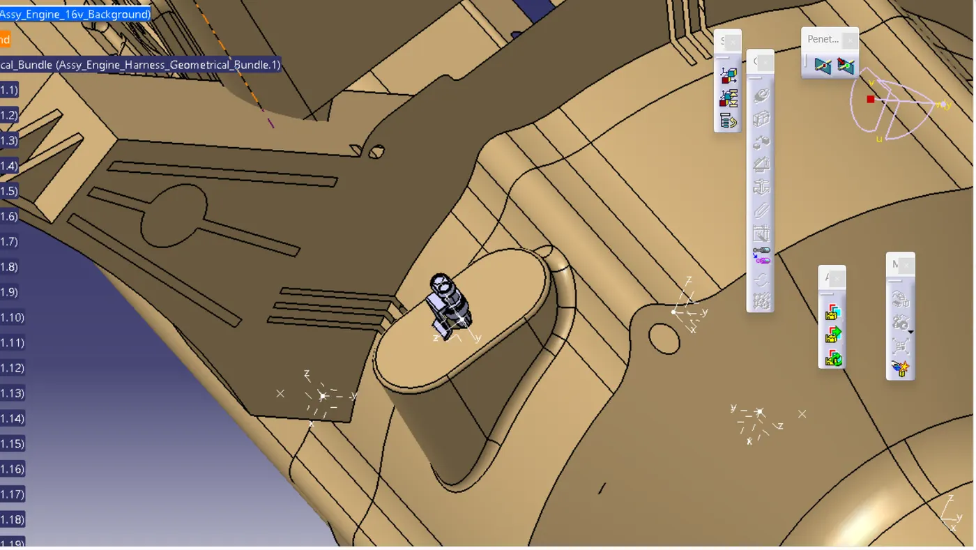
- first we need to position the connectors at desire locations using compass and smart move as below mentioned,
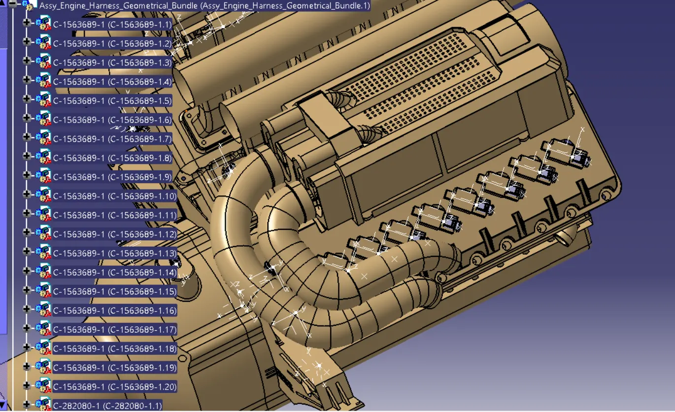
Fuel injector system:
- We need to position 16 connectors as per desired location.
Vehicle speed measuring sensor:
Neutral precision sensor:
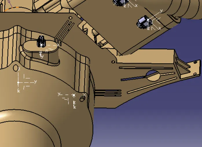
Engine coolant sensor:
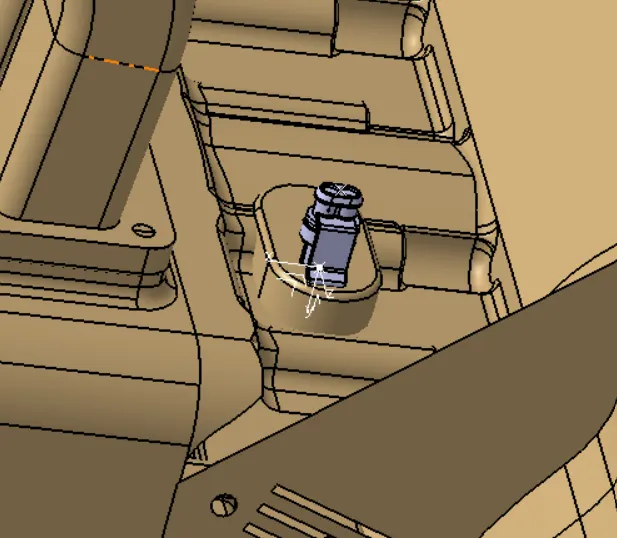
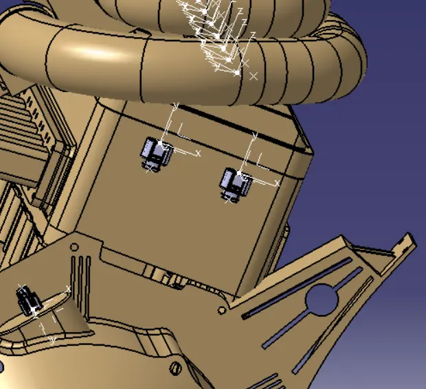
Engine oil pressure sensor:
- We need to use this connectors LH,RH Sides.
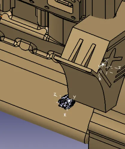
cam shaft sensor:
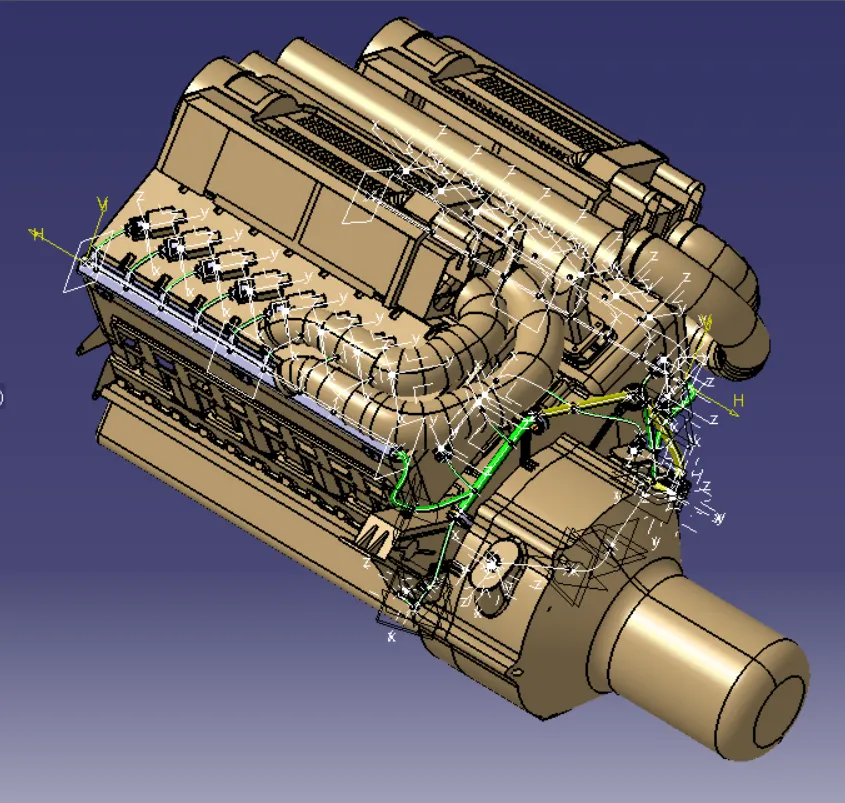
- Then we start our routing from interconnection point which is placed at near neutral precision sensor,then we need to create bundle segment with desire diameters.
- During the routing we need to use P clamps,Furtree clips desire location,it helps to non fouling the wires on the engine assembly,and it gives aligned position for the bundles.
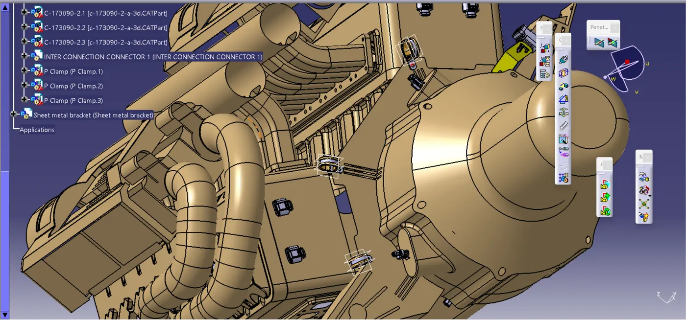
P clamp provisions:
- Using engine assembly Bolt provision we are fixing the P clamps inside the routing.
- Before that we need to define the p clamps electrically.
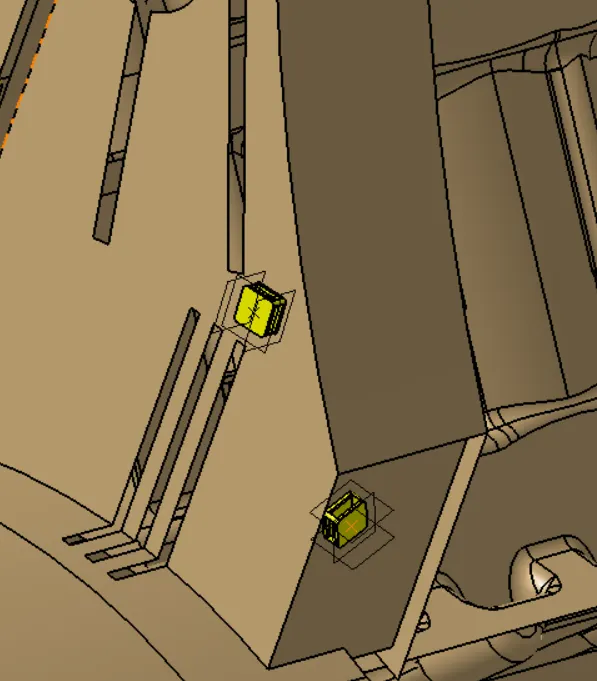
Fur tree clip Provision:
- For this we need to discuss with CFT team and CAE team for creating threaded holes for fur tree clips.
- It is mainly used for low cost and efficiently hold the bundles during the routing.
Protective channel:
- Protective channels are used to guide and protect the bundles from exhaust area,It may create heat and tear the wires because of the heat.Thats why we are create the channel assembly for LH and RH side of the Engine.
- We need to define the Chanel electrically.
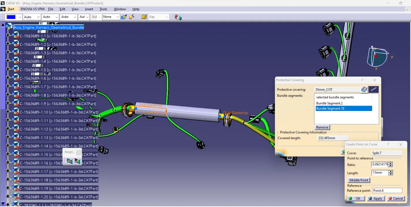
Protective Covers:
- It is mainly used for protecting the bundle from external affects and aesthetic purpose.
- During the design we need to ensure the tangency management,slack management and branching points before finilising the design.
- Then we need to check the continuty of the bundle segment and error.
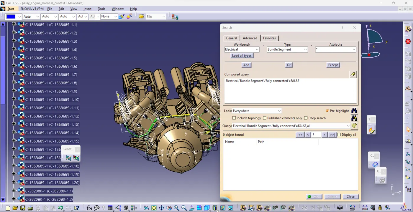
- Above mentioned diagram tells the routing was fully connected to each other and there is no error inside the tree area.
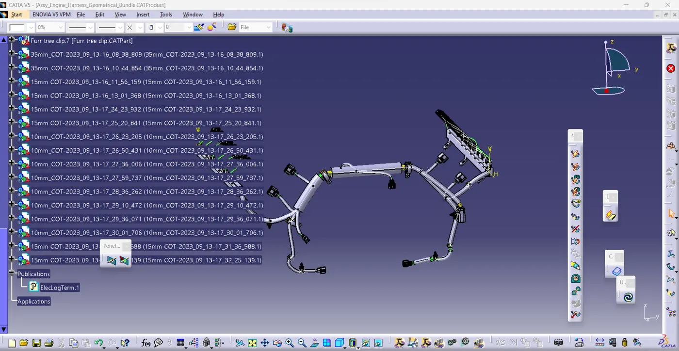
- After that we need to review with CFT team & manufacturability,serviceability team for the suggesstions.
5.ROUTING FINALIZATION:
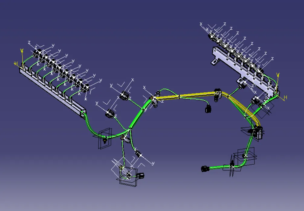
- In this stage we need to give detailing to the routing design by using standards used by OEMS.
- In this stage we need to consider selection gides,specification of components,selection parameters,clearances,protection devices and standards.
- In this routing design we are using AVSSF wiring harness for routing the design because it is thin wall thickness and high flexiblity.It is come under japanese standards.
- And here Slit Corrugative tubes are used because here we are create lot of branches during routing.
- Durinng corrugative tube selection we need to consider with temperature resistance,ID,OD,abrasion resistance,Resistance to hazardous liquid,color and etc
- Like this we need to finalize the components detaily as per our application.
6.FLATTENING AND HARNESS DRAWINGS:
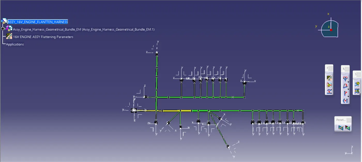
- Then we need to go the Harness flattening design interface,For this we need to create new product.
- Then we need to go create the harness flatten parameters and then extract the Geometric bundle assembly.
- And the flatten and rotate the branches as per our requirments.
- Then we need to create the 2D diagram for Manufacturing.
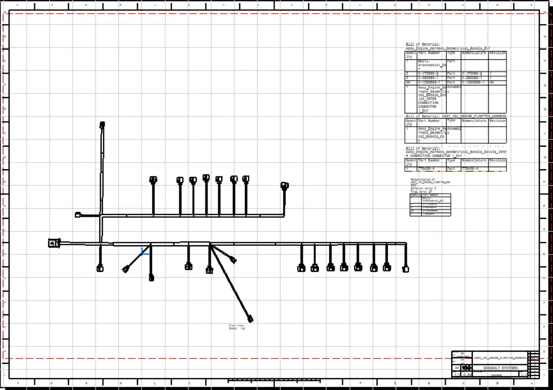
- In this we need to add the detail of Bill of material,length of the bundle,connectors type and its properties,protection cover details and etc....
- In this we need to change some drawing properties and input the front view of the flattened routing.
- Above mentioned diagram contains all those details.
- Then we need to Relese the diagram for manufacturing,first we need to create proto type and then we need to go for the production.
Conclusion:
- From this project we are learned the real time aproach for creating routing design for 16 valve Engine assembly as per industrial OEM wiring harness designing process.And release the drawing for Manufacturing.