Project 1
AIM:
Design and develop the Wiring harness on Given V6 Engine and Prepare flatten view drawing in CATIA V5. Application of all Packaging rules, Industry best practices studied in this course shall be demonstrated in design
INTRODUCTION:
A wire harness, also commonly referred to as a wiring harness, is an exterior sheath used to cover some types of electronic wires. Generally, wiring harnesses are made of thermoplastic or thermoset materials that can help protect the cables from the environment.
PROCEDURE:
- Define all the mechanical connectors electrically and save it in the Catalogue.
- Place all the connectors to the required positions on the given engine 3D CAD model
- Place P-Clamps and Fir Tree clips at the required position by following the packaging rules.
- Create the Wiring Harness Routing with all the electrically defined connectors and mounting equipments.
- Create branching points at required locations to create sub branches and connect to various connectors in the geometrical bundle.
- Apply Protection coverings as required.
- Create Wiring harness flattening for the final geometrical bundle.
- Using the drafting workbench, create a drawing sheet with the flattened wiring harness.
STEP 1:
create catalouge for connectors,cot tube,clamps and clips
STEP 2:
define connectors electrically and define bundle connection point and connector connection point
- 12-pin connector - C-776438-4
- connector 2
- connector 3
- connector 4
- connector 5
STEP 3:
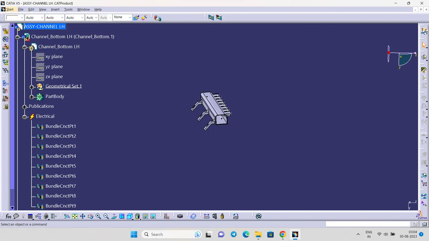
Define channel electrically
STEP 4:
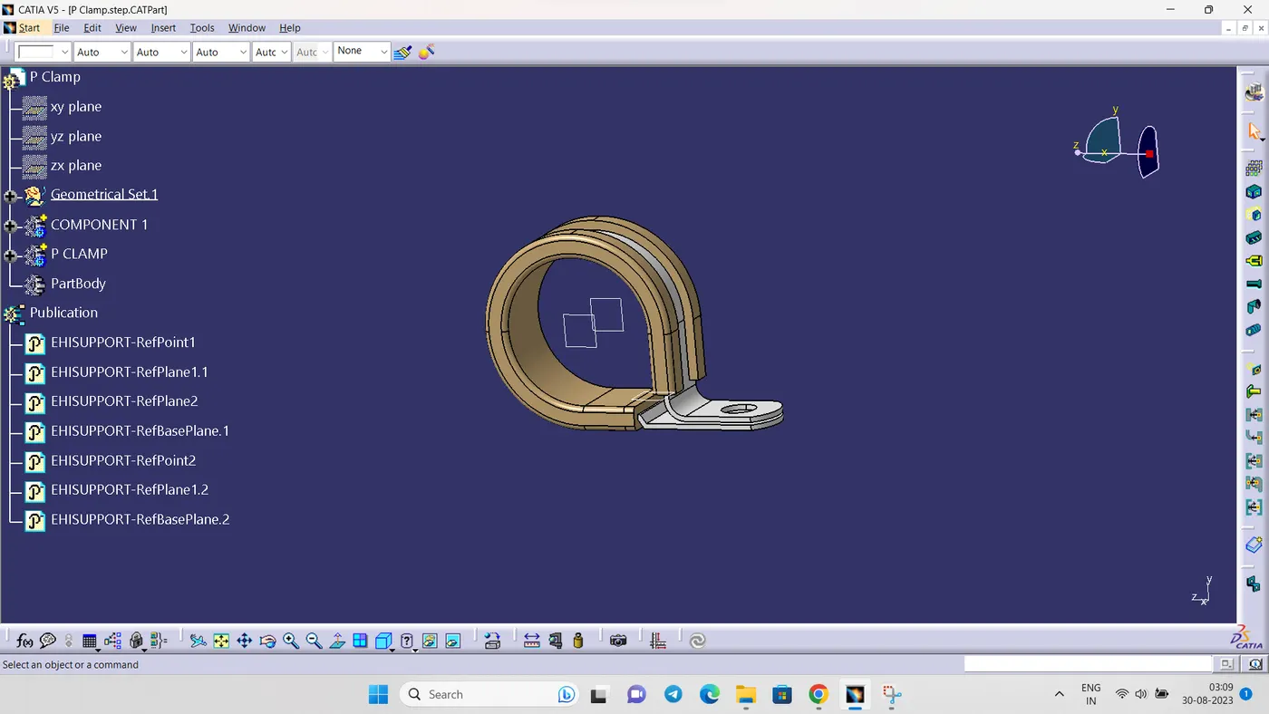
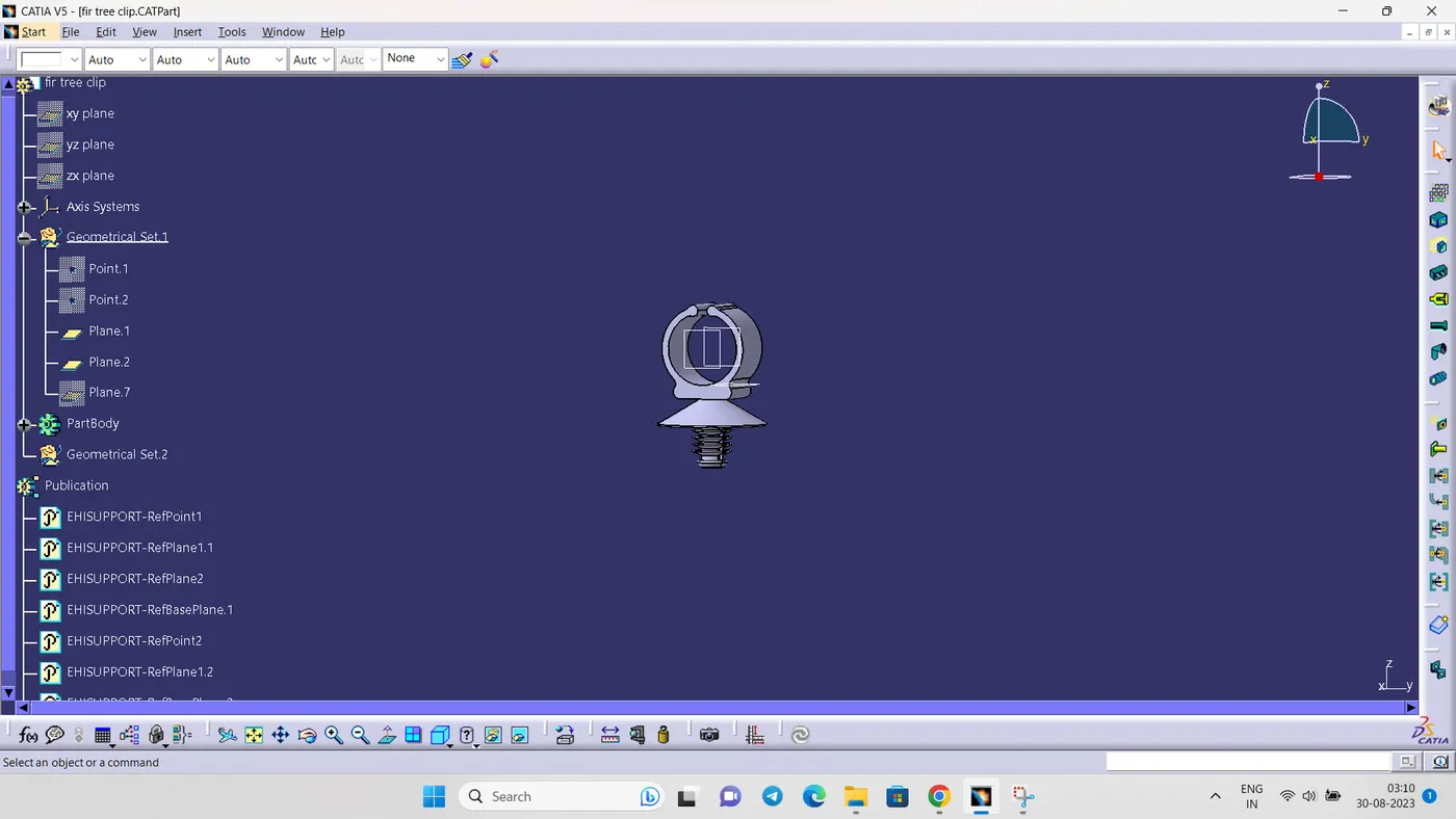
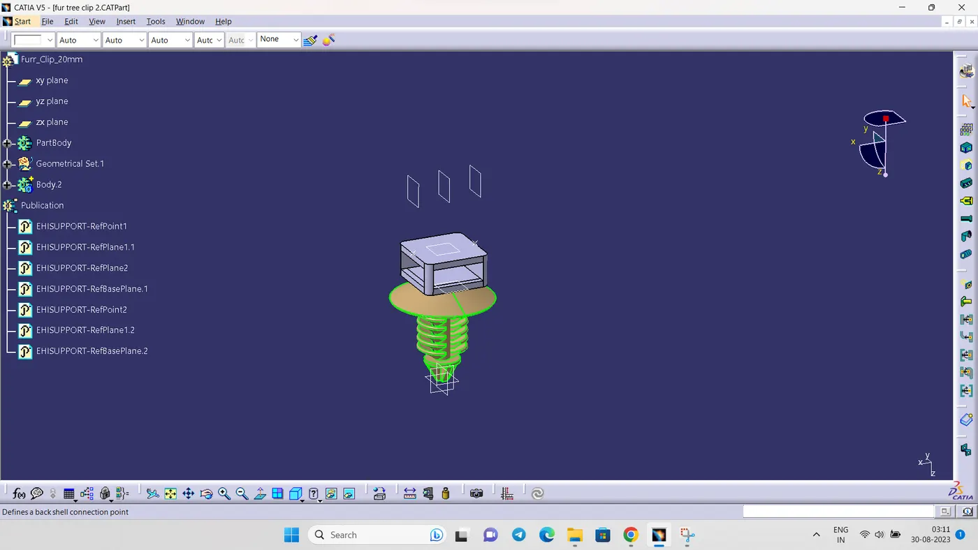
download and define the p clamp and fur tree clip
STEP 5:
- Create an context assembly
Context assembly is nothing but the product file which contains the engine 3D-CAD data and the engine harness geometrical bundle. Here the geometrical bundle product contains all the connectors and other mounting equipments, clips and clamps which are electrically defined for the assembly. Sheet metal L-clamp are added in the main context assembly.
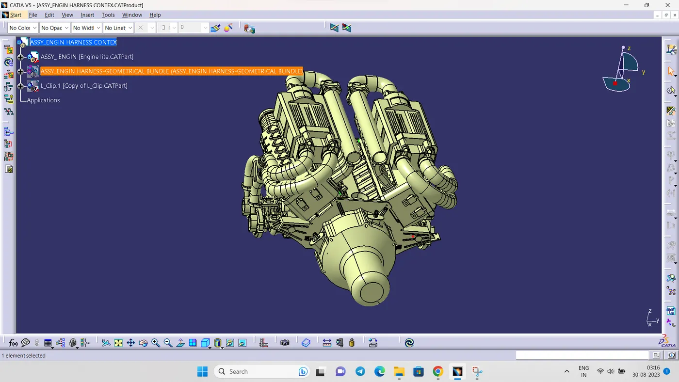
switch into the electrical harness assembly workbench and Geometrical bundle product file should be electrically defined using the Define Geometrical bundle option before adding any parts into it.
after add all the connectors into the geometrical bundle product file.
STEP 6:
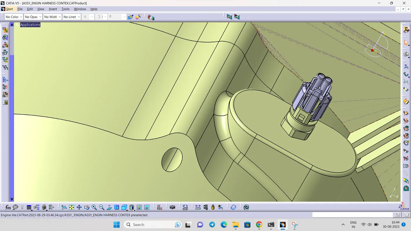
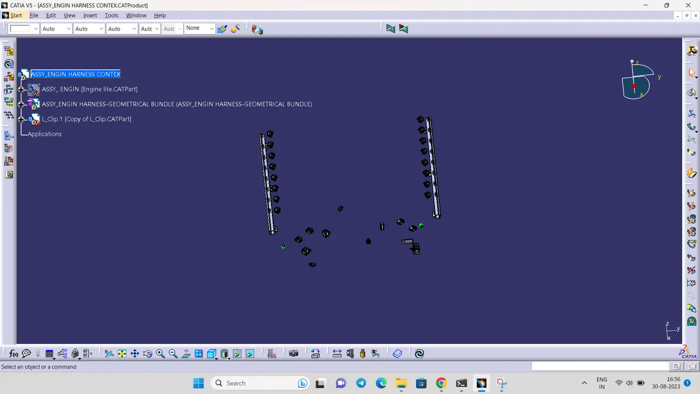
- Arrange all the components in the desired locations
4 pole connector to the fuel injector sensors in both sides .
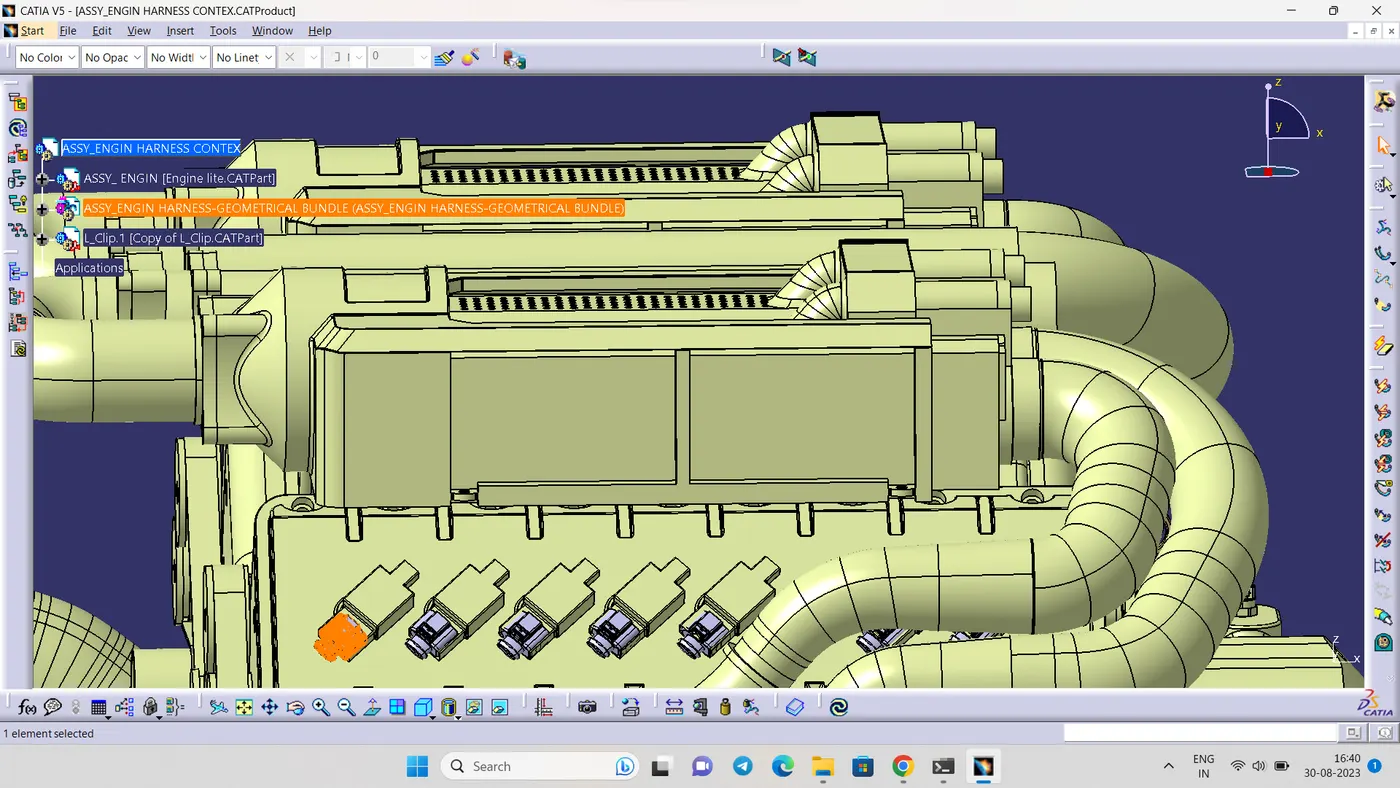
add all the connectors for the sonsors like coolant heat sensor,nutral position sensor,speed sensor
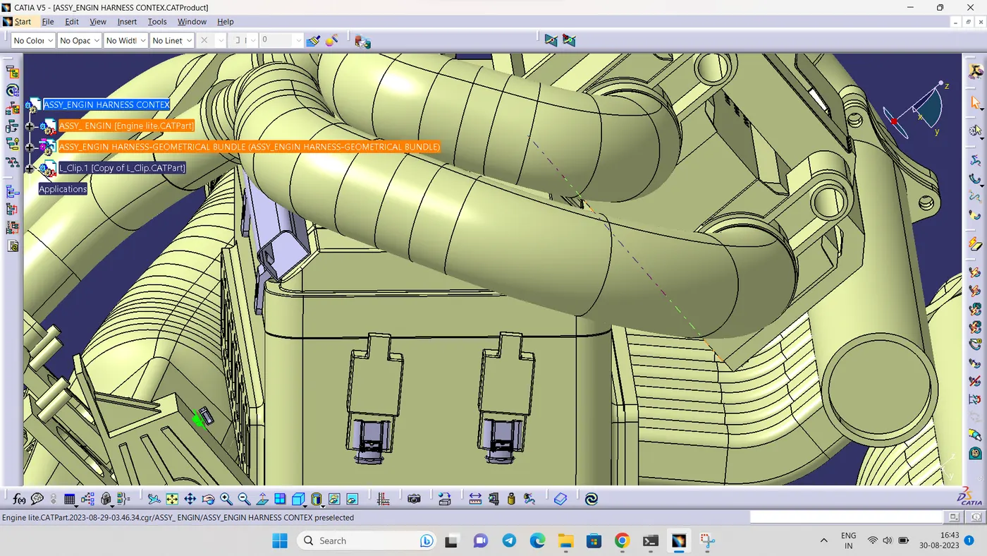
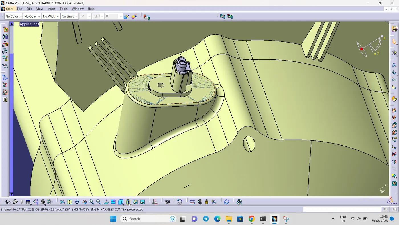
STEP 7:
- Place interconnection connector and l clamp
However, Situation of interconnection connectors are not similar to device connectors. Interconnection connectors are not parked with any device but should be parked with the Help of clips/clamps/ Sheet metal Bracket etc. Possible to the Packaging conditions
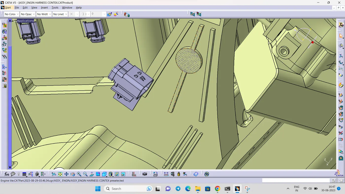
L clamp is added in the context assembly
STEP 8:
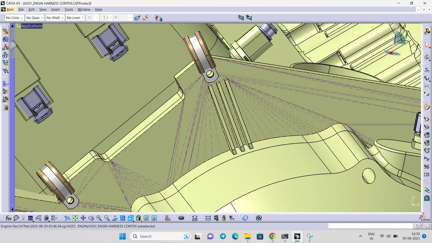
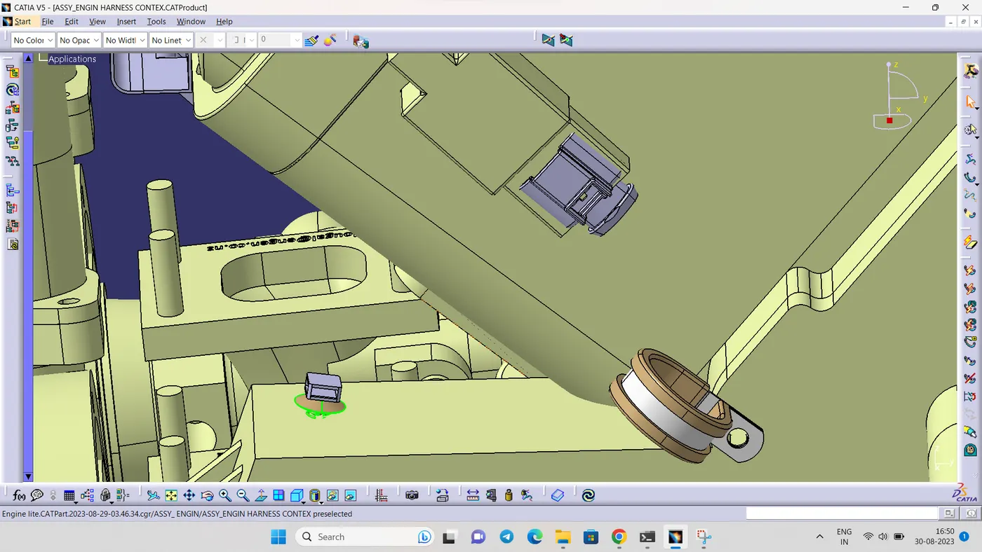
- Add p clamps and fur tree clip for proper routing of the harness bundle
STEP 9:
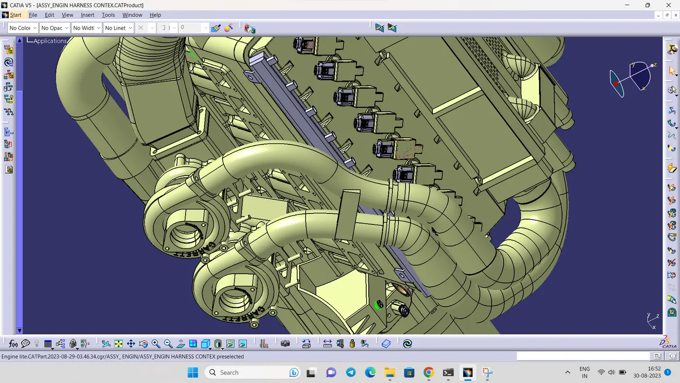
- Placement of the guiding channel
STEP 10:
- After place all connectors,clip,clamps and channels start routing
in the case of guiding channel bundle is created using the extrenal curve
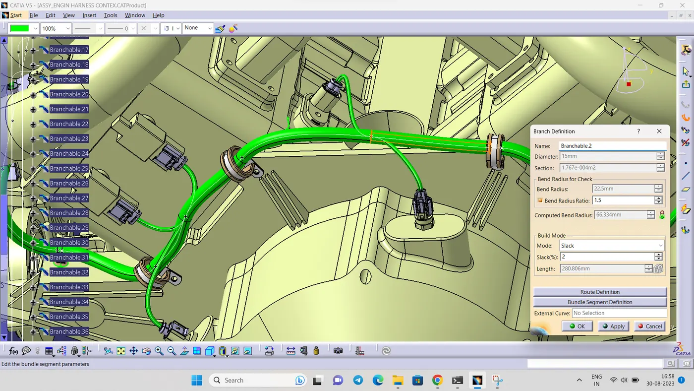
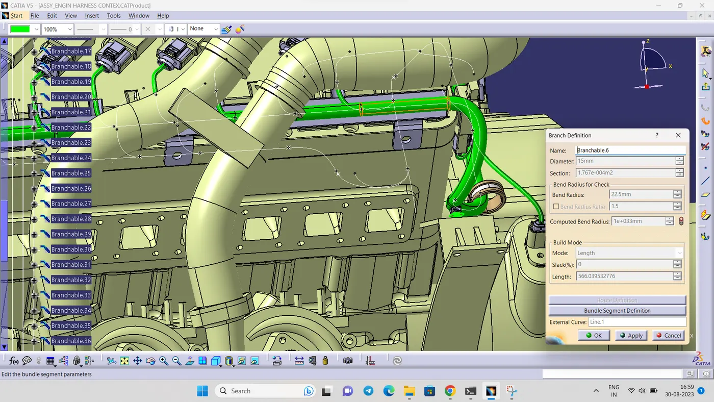
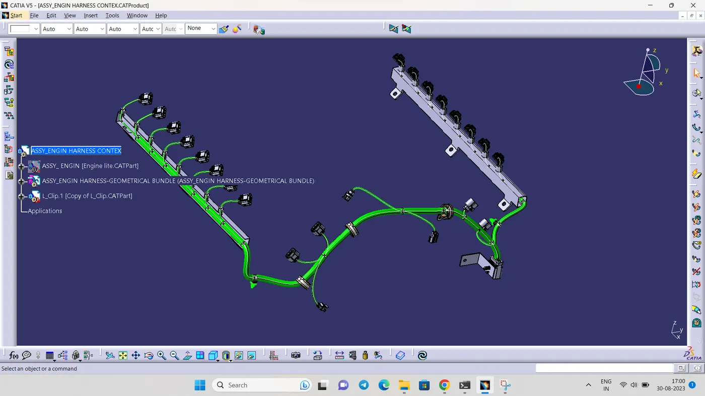
- add protection covering to the bundle
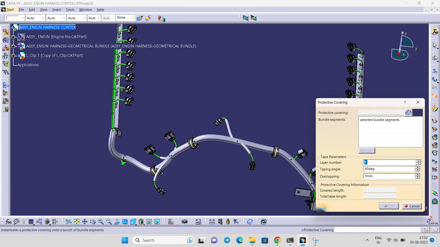
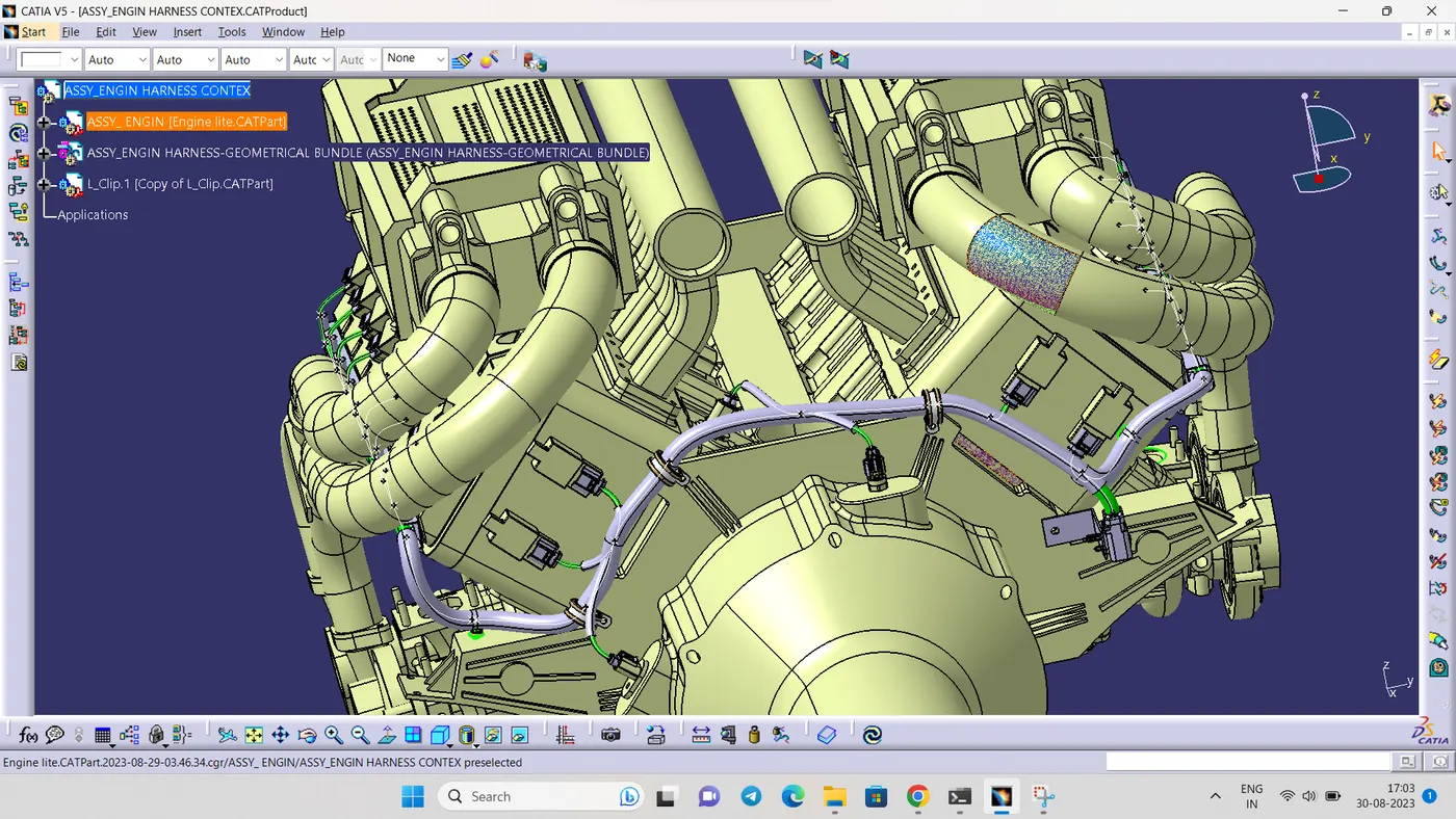
STEP 11:
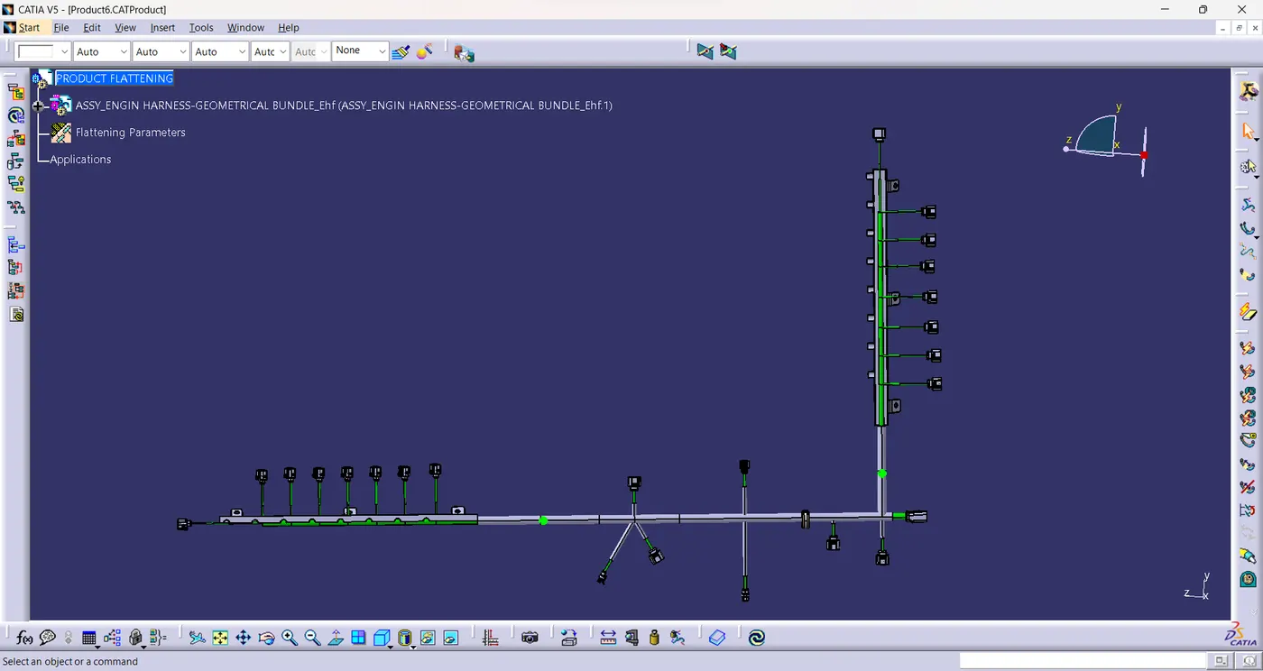
- wiring harnes flattening
Now we need to convert the geometrical bundle into a flattened wiring harness in the Electrical Harness Flattening Workbench
To create the Flattened Harness , We need to create a new Product file and switch into electrical Harness flattening Parameters and then Extract the geometric bundle from the Wiring Harness Context product file
Then Select all the Branches and Flatten the entire Geometric Bundle
STEP 12:
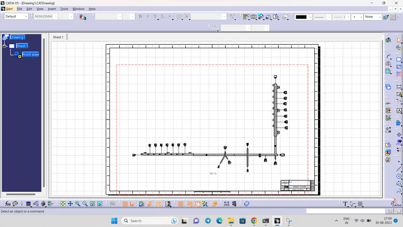
- Create a drawing file for the flattened harness product.
Insert the flattened harness product into the drawing sheet using view option and selecting the front view command
CONCLUTION:
In this project i have successfully routed the wiring harness for the Engine assembly and the flatten-view drawing was prepared in CATIA V5. Various packaging rules and constraints were considered while routing the harness
"IAM NOT ABLE TO ATTACH THE PART FILR BECAUSE IT IS MORE THAN 20 MB. SO I ADD IN THR DRIVE AND THE LINK GIVEN BELOW"
https://drive.google.com/file/d/1nocjvG41k4SECMUNs-coIIMwBeY9xGlG/view?usp=sharing
https://drive.google.com/file/d/1nocjvG41k4SECMUNs-coIIMwBeY9xGlG/view?usp=sharing