Project 1
Analyze and design a steel building to 10T CRANE as per IS standard code in TEKLA STRUCTURAL DESIGNER. Refer the attached plan and elevation. Provide bracings and moment connection for lateral stability.
Consider dead, live, equipment and wind loading. Consider the brick wall loading for 150mm thick and 1.5 KN per sq m for wall and roof cladding.
Assume wind loading basic speed as 39m/s
Report of each member to be generated and extract drawings of structural plans from the software
AIM
To Create a model by using Given Data and Design & analysis of the steel model.
PROCEDURE
- To open the new file ad save it.
- To create a Grids and Construction level, from taken the value of given Attachment.
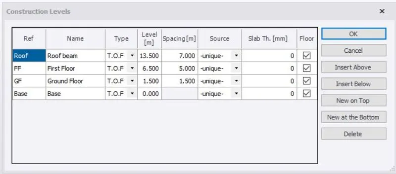
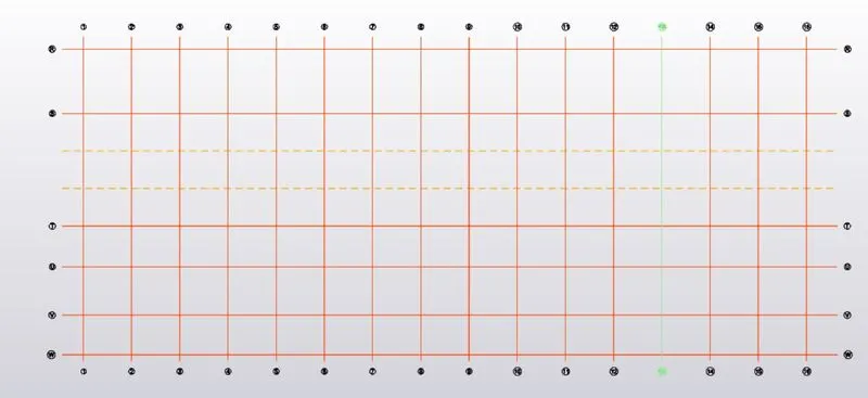
- Add the materials Of required categories of pedestrian, steel column, beam, slab, etc..,
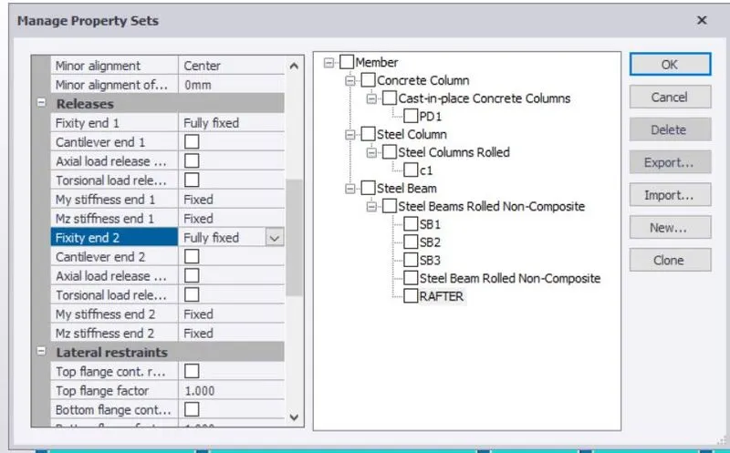
- Go to Manage properties set > to chose member > then to add required members.
- After adding all members, then to do the model.
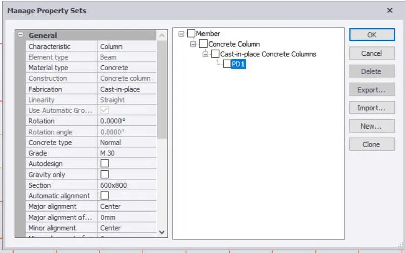
- Go to Base level, first we add the Concrete column.
- Go to Model > Choose concrete column > then to assign the column in Grids intersection point, after that to select the all column to add property set at required sections.
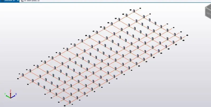
- Next we will add the steel column at Base level is Ground floor, before we add the Manage properties of Steel column.
- Go to model > steel column > add to the center point of grids where the column are needed.
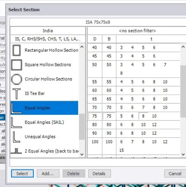
- To choose the steel type is ISMB.
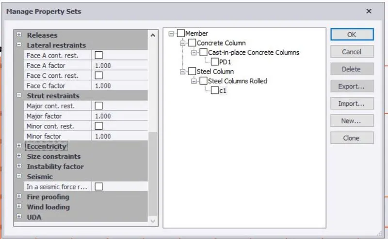
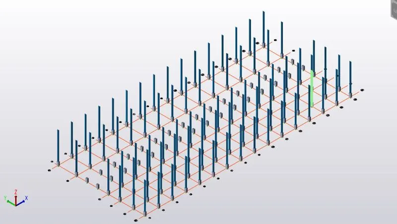
- Similarly we add the steel beam at required sizes of Different floor and check the given Data to analyze for beam strategies.
- Go to model > steel beam > to add the Grids line @ Ground floor, first floor, top beam level at different types properties based on load acting about the structure.
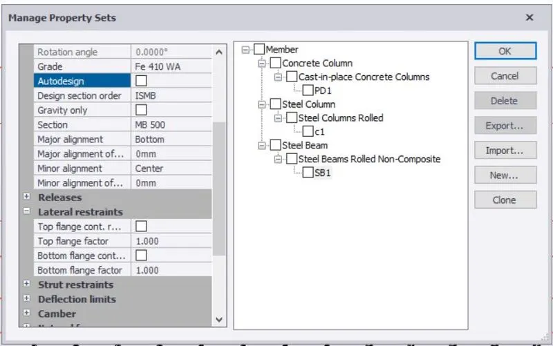
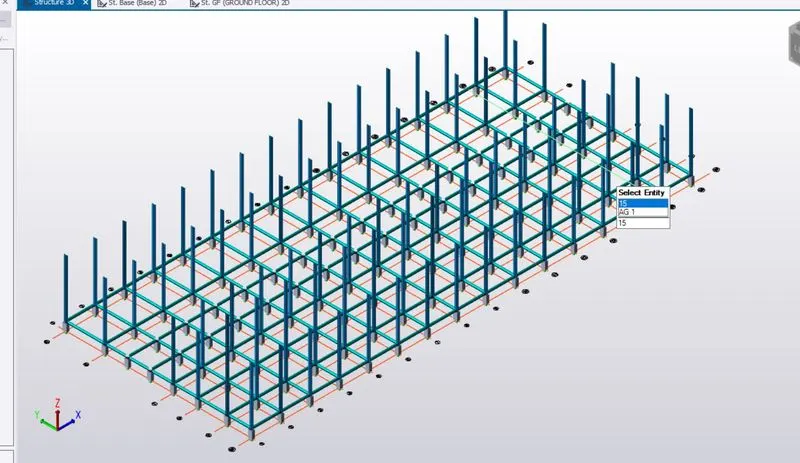
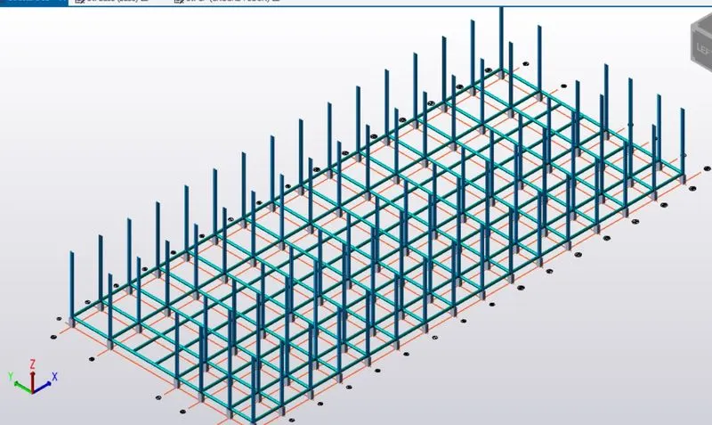
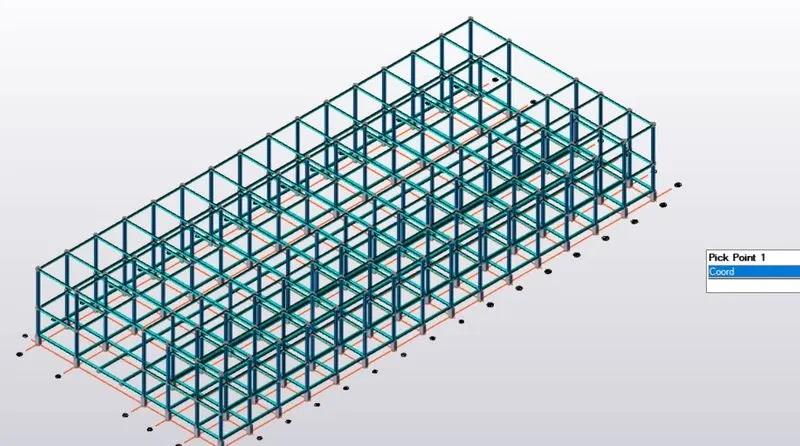
- Then, to create a frame to add each and every Gridline can easily visualize every frames.
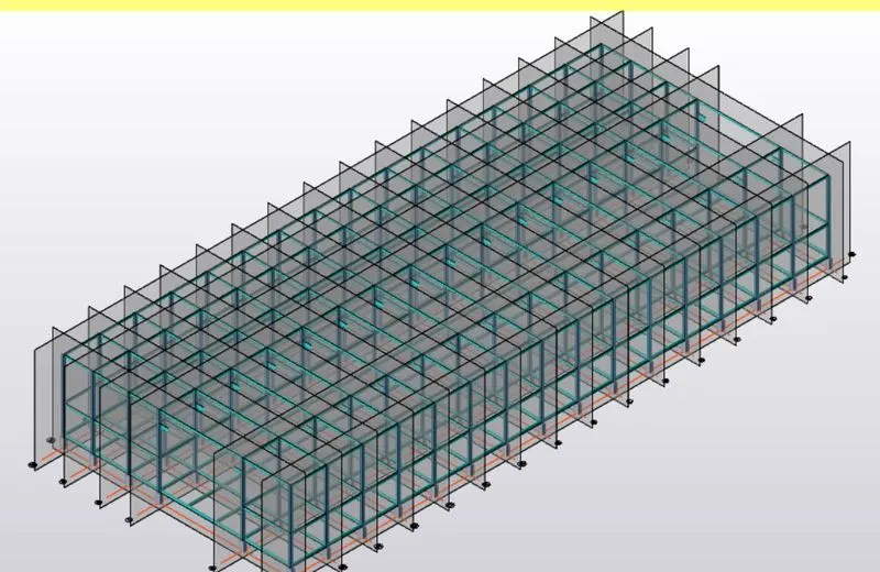
- Next, have to consider the similar process of adding the Rafter beam at top sloped level of model in under the support of the Roof panel.
- Here we choose the perfect steel beam to withstand all loading conditions.
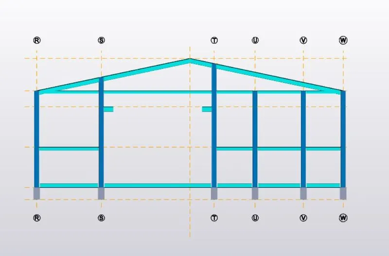
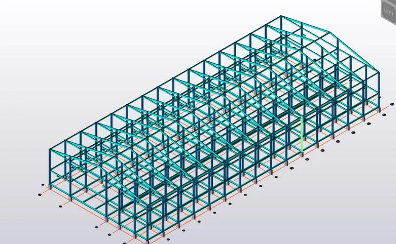
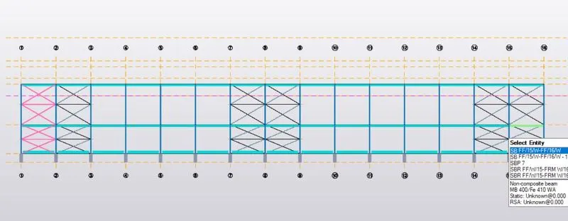
- Next, we consider adding a most important factor of the steel model, to the addition of bracing.
- The purpose of adding bracing to stabilize the main girders and frames and contribute to the distribution of load evenly and also to provide restrains to compression of flanges.
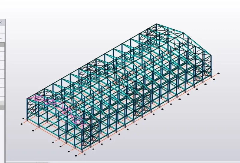
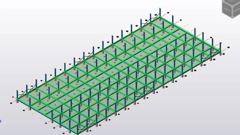
- Next to add the slab on beams.
- To check all dimensions of the slab area for we can able to understand the Slab properties of One way or two way.
- Before we check the Model for wherever have to provide the slab on beams.
- To add the slab Materials.
- Go to model > Slab > slab on beams.
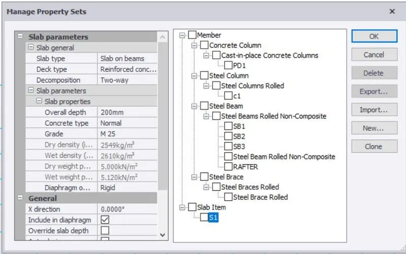
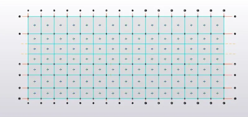
- To add the wall pannel on all four sides of model directly.
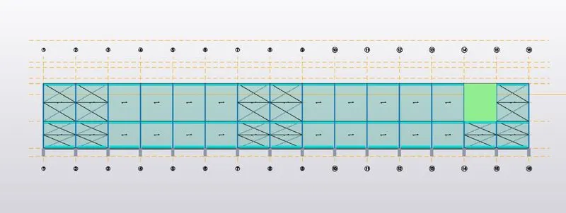
- similarly to add the Roof pannel on top surface of model.
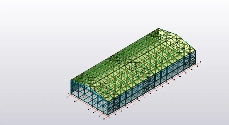
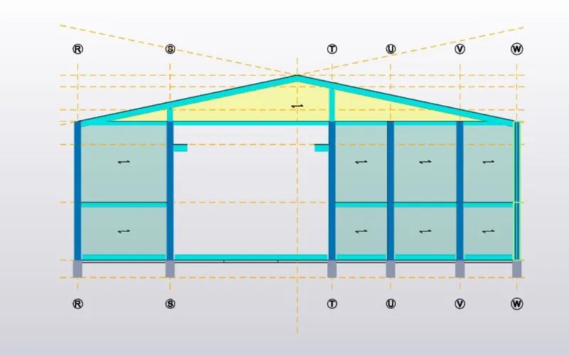
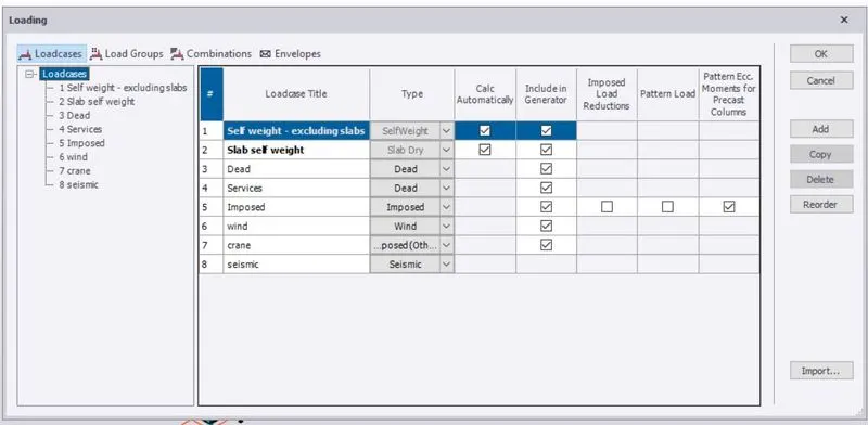
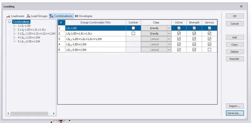
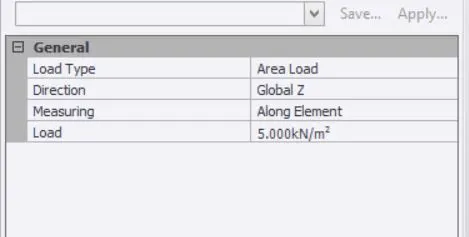
- Next, to contribute of a major factor on modeling the structure for Load cases, load combination.
- Before we calculating the load, to add load type in model and also all combinations.
Calculation of Dead Load
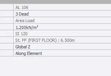
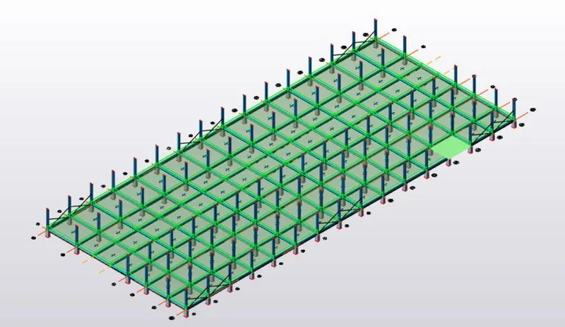
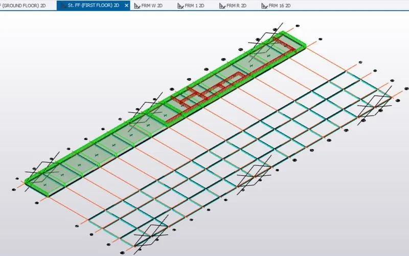
- Finishes Loading ( 50mm thick )
= 0.05 x 24
= 1.2 KN/m^2.
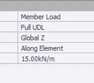
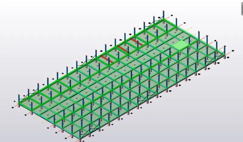
- Brick wall load with cement plaster thickness ( 150mm thickness)
Unit weight of brick wall = 20KN/m^3
@ Ground floor to First Floor ( 5m height )
= 0.150 x 20 x 5
= 15 KN/m.
@First floor to Top floor ( 7m height )
= 0.150 x 20 x 7
= 21 KN /m.
Calculation of Live Load
As we taken the value of all areas of Live Load from IS 875, PART-2, TABLE-1.
- Store room = 5 KN/m^2.
- Office room = 3 KN/m^2.
- Rest room = 2 KN/m^2.
- Toilets = 2 KN/m^2.
- Staircase = 5 KN/m^2.
- Equipment Room = 10 KN/m^2.
- Conference Room = 5 KN/m^2.
- Flat roof = 0.75 KN/m^2.
Next to calculating wind load at all direction
- Basic wind speed, Vb = 39m/s.
- Terrain category = 2
- Class of structure = A
- One horizontal dimension of structure, L = 90m
- Another horizontal dimension of structure, W = 38 m
- Eaves level height of structure, h = 15 m
SOLUTION
- Ratio of wall and Roof Co-efficient
Wall , L/W = 2.36
h/w = 0.39
ROOF, h/w = 0.39
- As per reference of IS 875, Part – 3, Table =5.
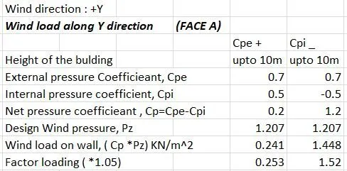
- To find external pressure co-efficient(CPe) for walls.
The condition is satisfied in,
Here diagram from is
- To find Design Wind pressure (Pz).
Pz = 0.6*Vz^2.
- To find Vz,
Vz = Vb * k1 * k2 * k3* k4
Therefore,
As we take value of k1, k2, k3, k4 from IS 875.
K1 = 1 ( under basic wind speed)
K2 = 1.0 ( height upto 10m)
K3 = 1
K4 = 1.15 ( for industrial building )
Vz = 39 *1*1*1*1.15
Vz = 44.85 m/s
Then to find,
Pz = 0.6 * (44.85) ^2
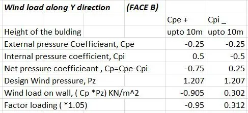
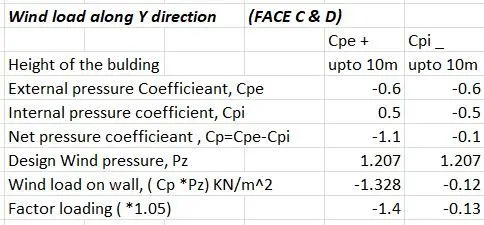
Pz = 1.207 KN/m^2.
- To find Wind load on wall.
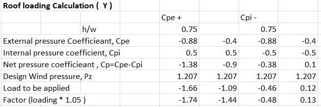
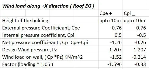
- To find the wind load on Roof.
The height of the Top roof level = 13.5m
Ratio =H/W = 15/38 = 0.39
Roof angle = 18 degree
As we take internal pressure coefficient , from IS 875, CLAUSE 6.2.3.3
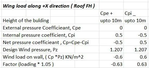
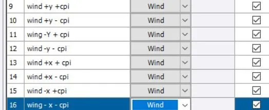
- After calculating the wind load, to add all directions of wind forces at Load cases.
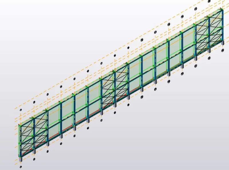
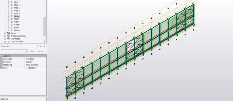
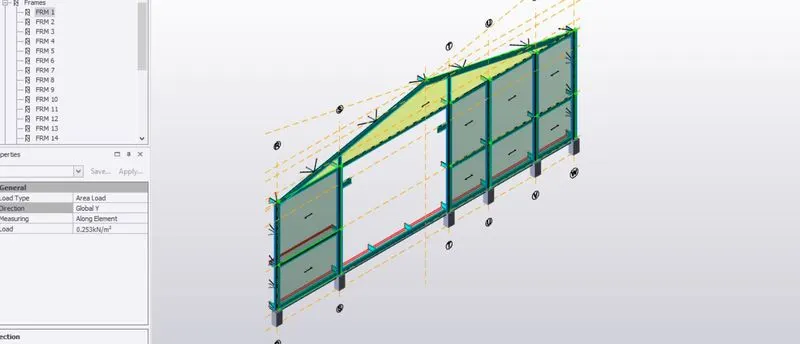
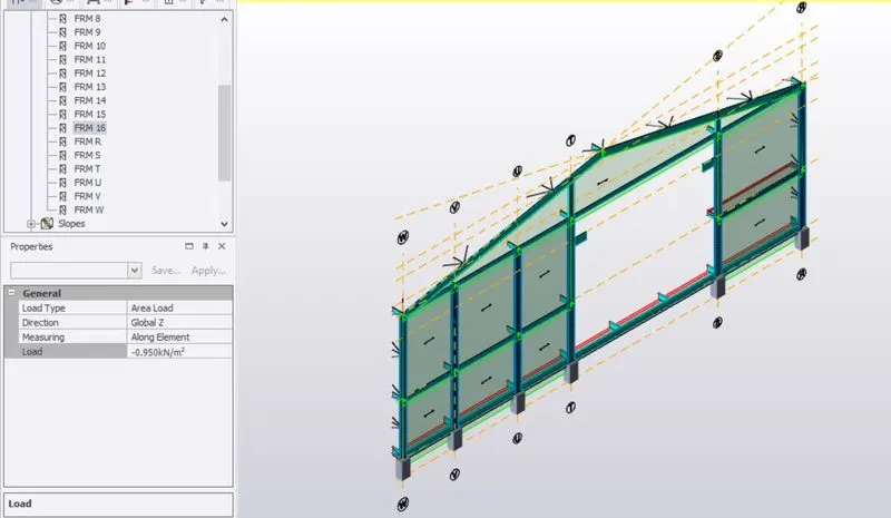
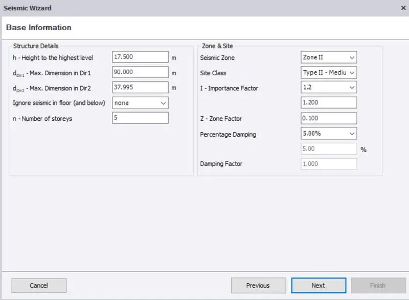
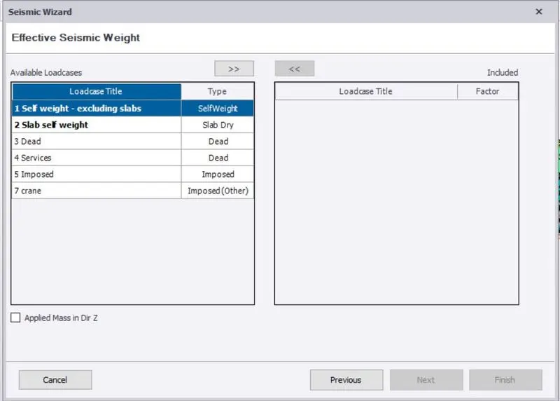
- Similarly to consider the seismic load on structure with standard parameters.
Crane load calculation :
Data :
Crane capacity = 10 ton = 100 KN
Weight of the crab = 35KN
Weight of the crane = 160 KN
Maximum Hook Approach = 1 m.
Wheel base = 3m
Distance between the C/C gantry rails = 20m
Distance between the C/C gantry columns = 6 m
Crane Type = M.O.T
Solution :
Maximum wheel load
= 100 +35
= 135 KN.
Self weight of the crane will act as uniformly distributed load of intensity
= 160 /20
= 8 Kn/m
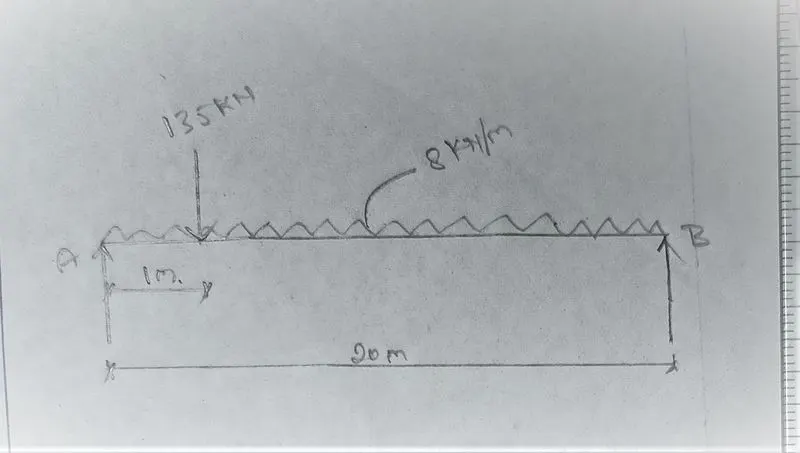
Taking moment about B :
Ra x 20 -135x19 -8 x20 x10 = 0
Ra = 208.25 KN.
Taking moment about A :
Rb x 20 -135 x 1 -8x20x10 = 0
Rb = 86.75 KN.
Maximum wheel load on each wheel
= Ra/2
= 104.125 KN.
Maximum Bending moment :
Let we assume,
Self-weight of the gantry girder = 1.5KN /m
Self-weight of rail = 0.3KN/m.
Total dead load
= 1.5 + 0.3
= 1.8 Kn/m.
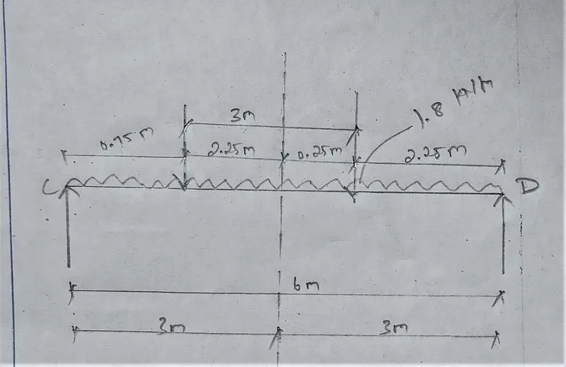
At D,
Rc x 6 -104.123 x (2.25 +3) -104.125 x 2.25 = 0
Rc = 130.15 KN
At C,
RD x 6 -104.125(0.75+3) – 104.125 x 0.75 = 0
RD = 78.09 KN
RC + RD = 208.25 KN
Bending moment under a wheel load due to live load
= 78.09 x 2
= 156.18 KNm
Bending moment due to impact
= 0.10 x 156.18(10% due to M.O.T)
= 15.618 KNm.
Total bending moment due to live load and impact load
= 171.79 KNm
Bending moment due to dead load
= 8.1 KNm.
Maximum bending moment
= 171.79 + 8.1
= 179.89 KNm.
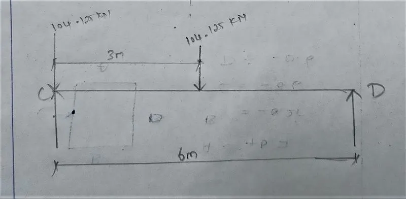
Maximum shear force :
At D,
RC x 6 -104.125 x6 – 104.125 x 3 = 0
RC = 156.18 KN
Hence,
The maximum shear force due to wheel load is
= 156.18 KN.
Lateral Forces
Lateral force transverse to rails = 5% of the weight of crab and weight lifted
= 0.05 x 135
= 6.75 KN
Therefore, lateral forces on each wheel = 3.375 KN.
Maximum horizontal reaction due to lateral force by proportion at C,
= 3.375 X 130.05 / 104.125
= 4.21 KN.
Horizontal reaction due to lateral force by proportion at D,
= 3.375 x 78.09 / 104.125
= 2.53 KN.
Bending moment due to lateral load
= 3.375 x 15.18 / 104.125
= 5.06 KNm.
RESULTS
Finally to analyze and Design the given model of steel building and also we calculated crane load, dead load, live load as per Indian standard.