Project 1
AIM
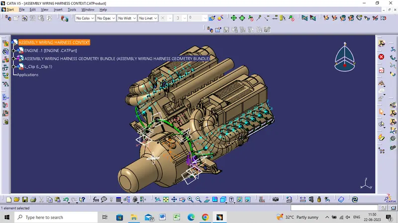
- To design and develop the Wire Harness Routing for the given V16 Engine by following the design and packaging rules.
OBJECTIVE
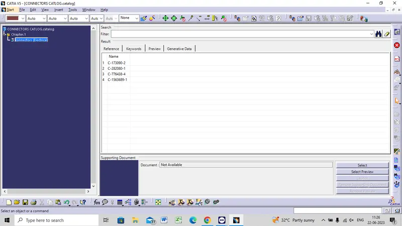
- To define all the connectors electrically and save it in the Catalogue.
- To place all the connectors and cavities at the required position.
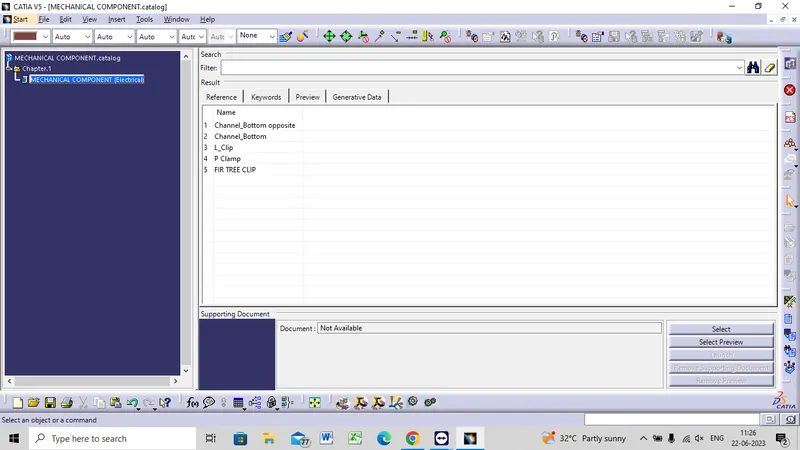
- To place P Clamps and Fir Tree clips at the required position by following the packaging rules.
- To create the Wire Harness Routing as per required and create branch points wherever required and also by following the packaging rules.
- To create the Wire Harness Flattening of the above routing.
- To display the flattened view in the drawing sheet.
Step 1
- Create a product file as 'Engine Wiring Harness Context' in which all the part and product files will be assembled which are required for the routing.
Step 2
- Create another product file as 'Engine Geometric Bundle' where all the connectors are added to it and the final routing is a part of this product file.
Step 3
- Now add the V16 Engine, Geometrical Bundle file and other required parts or products to our main Engine Wiring Harness Context' product file.
Step 4
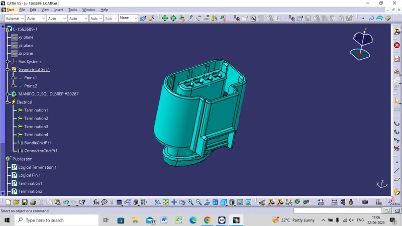
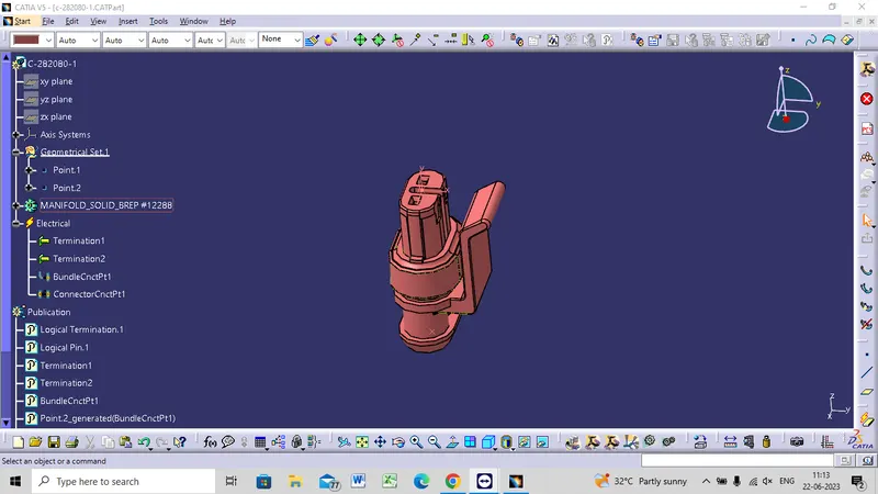
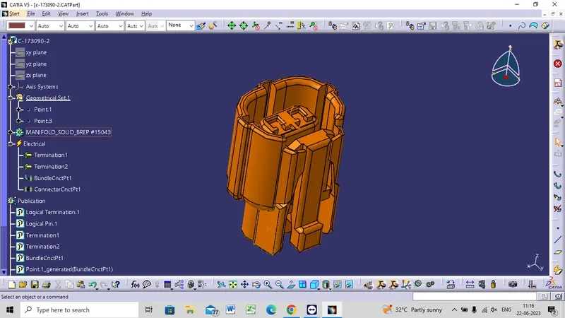
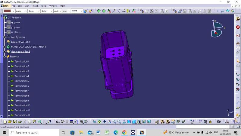
- Electrically define all the connectors, cavity clips and channel part and define the Connector Connection Point and the Bundle Connection Point.
- After electrically defining each and every connector save it in the Connector catalogue so that it can be used later.
ELECTRICALLY DEFINING CONNECTORS
C-1563689-1
C-282080-1
C-173090-2
C-776438-4
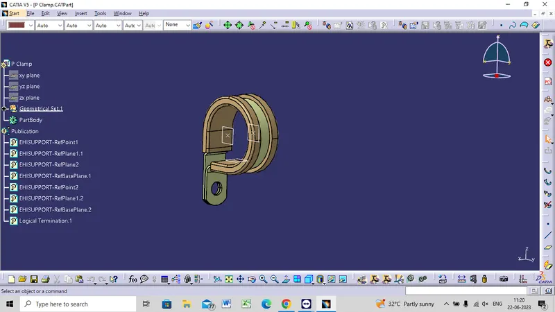
P - CLAMP
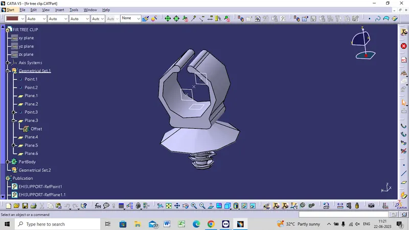
FIR TREE CLIP
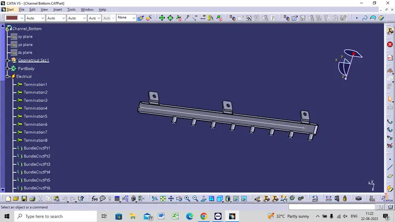
CHANNEL BOTTOM LEFT SIDE
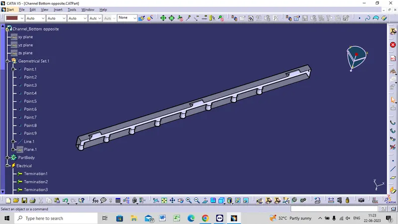
CHANNEL BOTTOM RIGHT SIDE
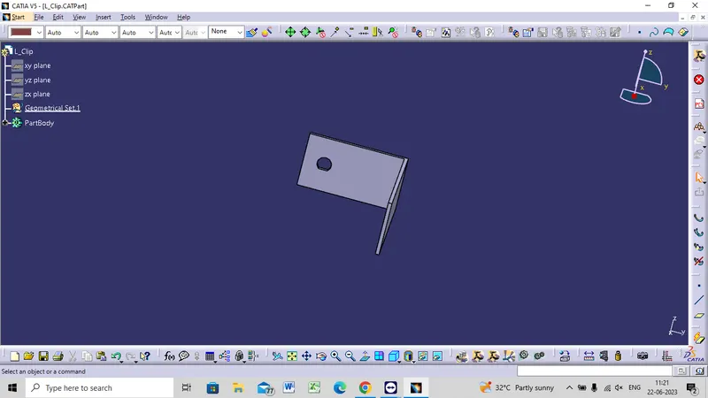
L CLIP
CATALOGUE
Add all the connectors to the Geometric Bundle product file and place them using the 'Smart Move' or 'Manipulation Tool' command and the compass into their desired location.
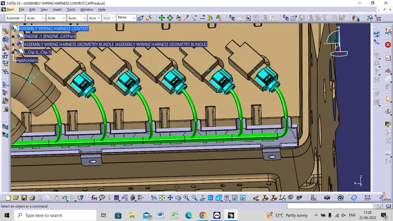
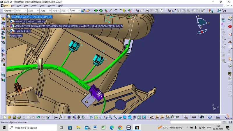
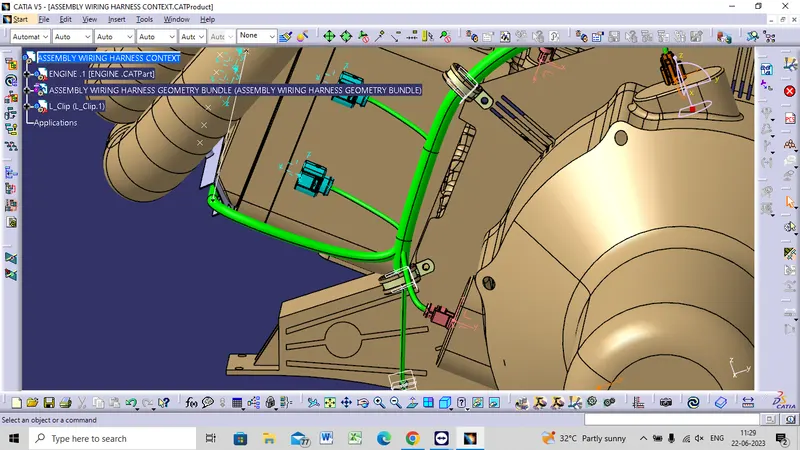
LOCATION OF THE P - CLAMPS
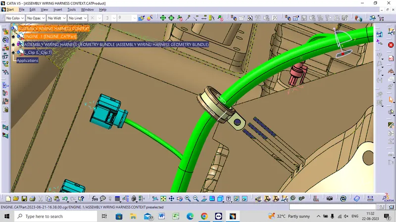
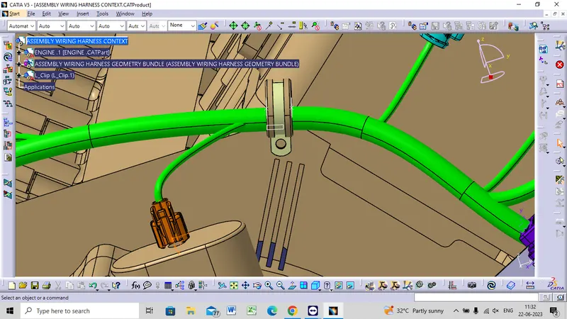
we can start the routing of the wire and provide clipping and clamping wherever necessary
during the routing process.
ROUTING WIRE
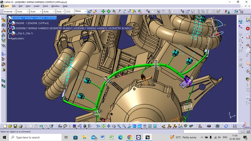
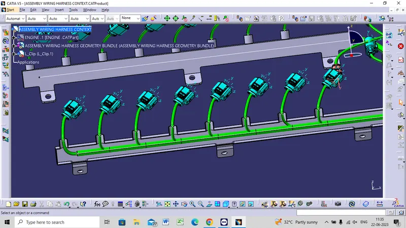
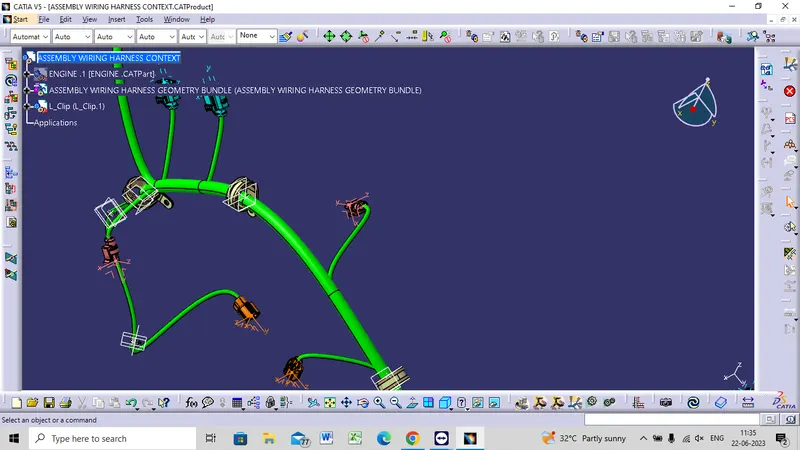
- After completing the routing, we need to check that if any of the bundles is interacting with the Engine part.
- There must be proper clearance between the wire bundle and the engine part.
- Additional slack or Fir tree can be placed to ensure proper routing.
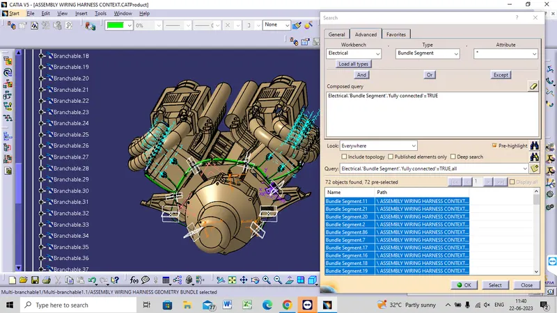
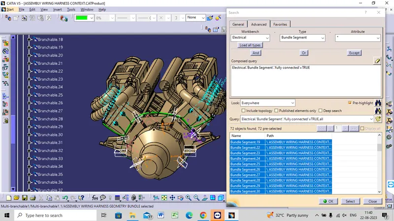
- We need to ensure that the entire bundle is fully connected.
BUNDLE CONNECTIVITY
FLASE
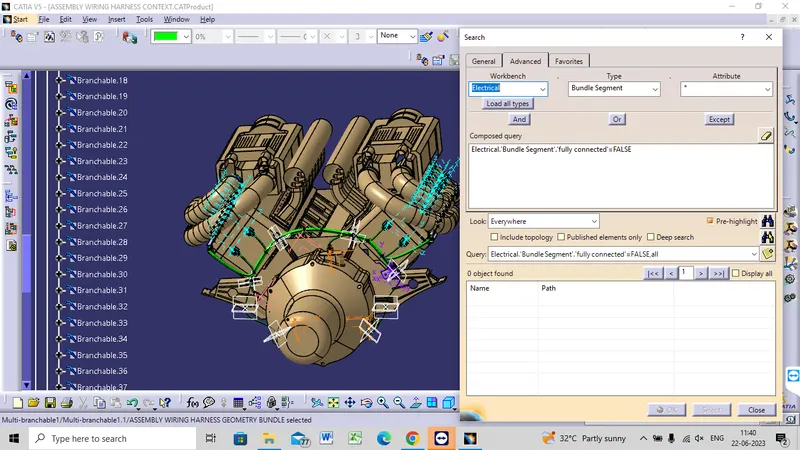
TRUE
FLATENING
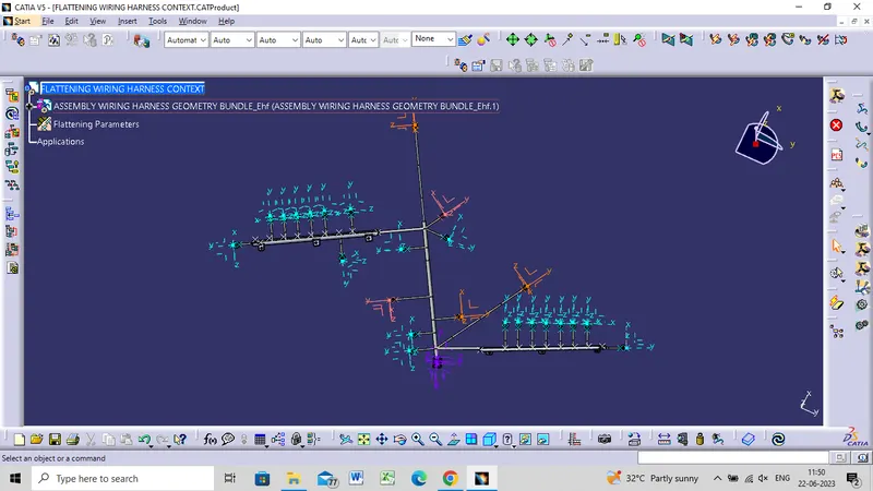
- After finally completing the wire harness routing by following the packaging rules we need to flatten our wire harness assembly.
- To create the wire harness flattening we need to create another product file and navigate to the 'Electrical Harness Flattening' workbench.
- In the workbench first we need to define the Harness Flattening Parameters and then Extract the geometric bundle from the wiring harness context product file.
- Then we can select all the branches and flatten the entire Geometric bundle.
- If all the bundles are fully connected then by selecting 'select all branches' the entire bundle can be selected and flattened.
- The bundles can be rotated and rolled with a proper radius in order to fit the drawing sheet.
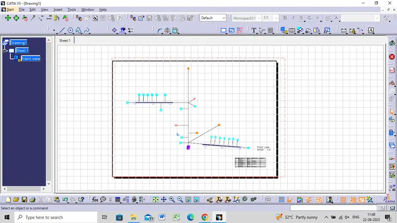
FINAL OUTPUT
CONCLUSION
- From the above project we learnt how to route wire harness on a V16 Engine.
- We also learnt about different packaging rules that must be kept in mind during wire routing.
- We also learnt how to flatten the wire and represent it in the drawing sheet.
- After finalizing the wire routing, we can request the corresponding Engine design team to provide additional holes for the mounting of Fir tree clips.