Project 1
Aim:
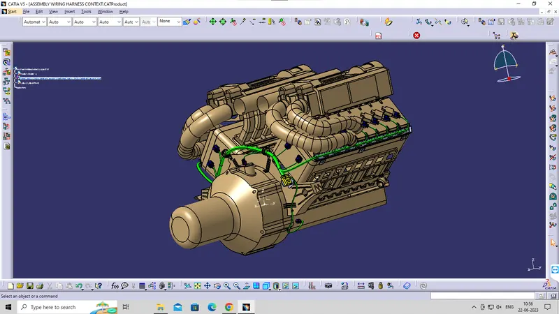
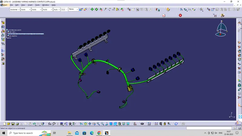
Route the wiring harness for the bugatti v16 Engine assembly and prepare flatten- view drawing in catia v5.
Objective:
The objective of the project is route the wiring harness and prepare flatten view drawing for buggati v16 engine. all types of pacakaging rules and constraints have to be considered while routing the harness. industry best practices should be implemented in the harness design. All necessary details like clearance/ clamping selection, harness fixing requirements, harness continuity should be provided in order to design the wiring harness.
Content-
Step 1- creating context assembly
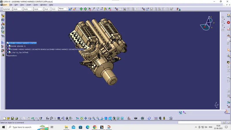
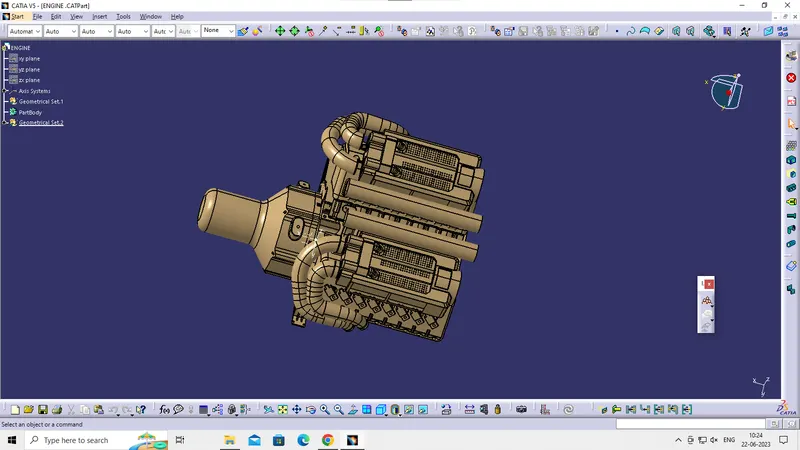
A context assembly has to created which will serve as the main assembly for the engine harness. the context assembly will cointain the 3D-CAD data for the bugatti v 16 engine and the engine harness geometrical bundle. if any sheet metal brackets are required then they are added in this ASSY ENGINE HARNESS CONTEXT.
Step2- Definig the connector electrically
The connector used for thus harness assembly . The 3D CAD data for this connector was downloaded from te. com. To define the connector electrically we should define the geometrical parameters, bundel connection point and the connector- connection point for the downloaded connector.
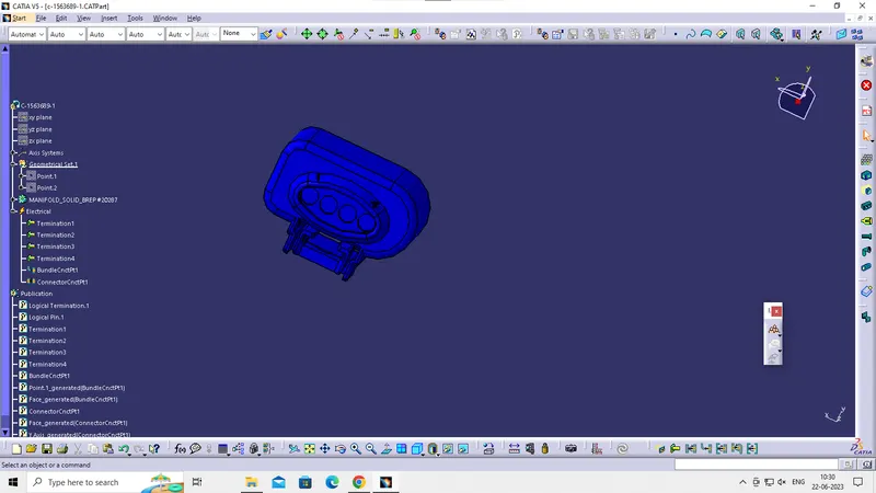
Step3- Adding connectors to all 16 fuel injector sensors ans 4 cam-shaft sensors.
All the connectors have to ba added inside the engine harness geometrical bundel assembly. manipulation toola along with a compass, snap, and smart move features should be used to locate all the 20 connectors .
First, connectors are lpocated for the first 8-fuel injector sensors which are on the left side of the engine. Then they are located for the 4 cam shaft sensors. at last, the remaining 8 connectors are added to the 8 furl injectors on the right side of the engine.
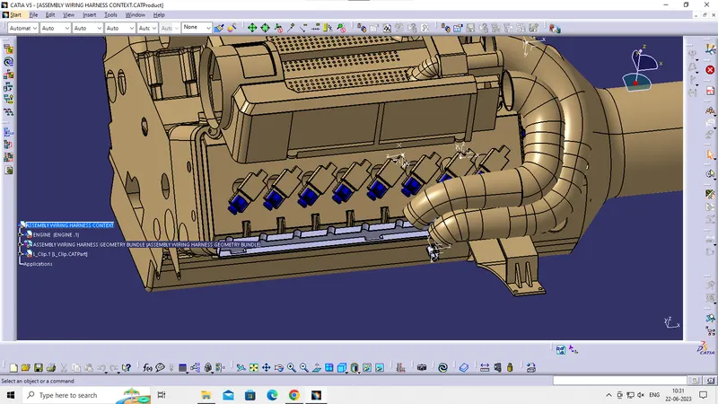
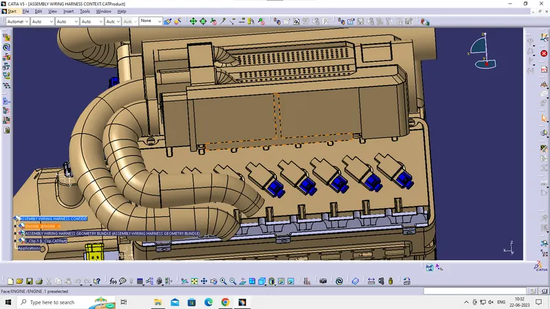
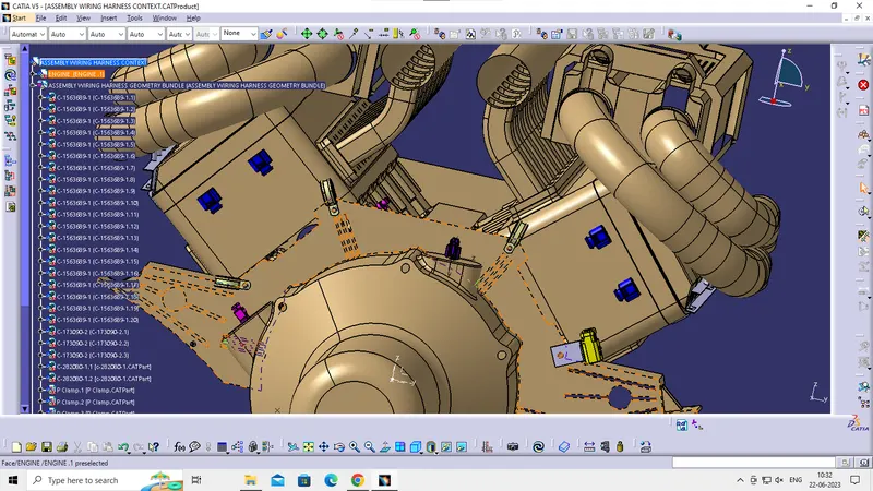
Step4- sheet-metal bracket for mounting interconnection connector
A sheet- metal bracket has to be created in order to provide mounting for the interconnector. We have to make sure that the bracket is placed inside the context assembly outside the engine and harness geometrical bundel assembly. the bracket can be mounted on the existing bolt located aas shoen below . it has to be made sure that in real world application if we are using any existing bolts or screws then design idea has to be discussed and passed by the engineering team in order to make sure the proper function of the engine.
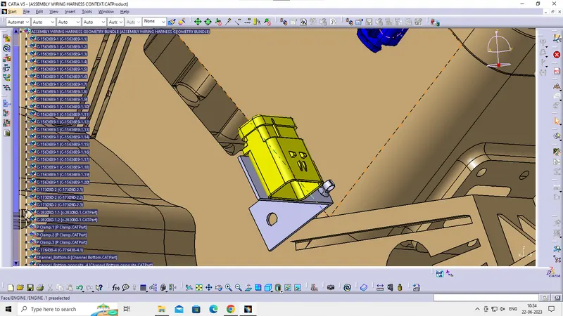
Step5- Defining the interconnection connector and mounting clip electrically and then mounting it on the created bracket. mounting p- clamps for the wire harness.
The 3D- CAD data file for the required connector and the cavity is downloaded from te. com. Both the connector and cavity are electrically defined and mounted on the sheet-metal bracket.
A total of 3 p- clamps are used for this wiring harness. they are all mounted on the periphery of the casting on the already existing bolts.
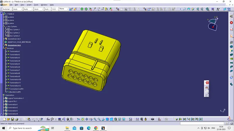
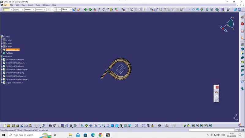
Step 6 plastic guiding channel
The bugatti v16 engine has 8 fuel injectors on the left side and 8 fuel injectors on the right side of the engine. All these fuel injector sensors are located very close to each other. so, the best way of route the wires around them is byusing a plastic guiding channel as they will help us organizze all the wires very precisely and will reduce complex wiring harness routing. Tomount the plastic guiding channels we would need some mounting provisions. The engine design team can be consultes and asked to provide mounting threaded holes or threaded bosses.
There will be two different plastic guiding channels for this engine. one for the left and the other for the right side of the engine.it has to be made sure that proper Clearance ( at least 50 mm ) is provided between the plastic channel and the exhaust pipes. the total thickness of the these channels is 25mm.
the next stwp is to define the guiding channel electrically we. have to define it as equipnment and define 8 bundle entry points leading to the fuel- injectors connectors and 1 bundle entry point along the entry face of the channel
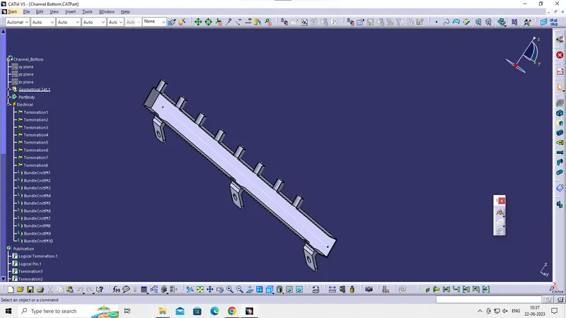
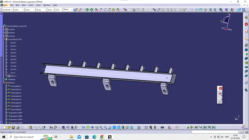
Locating the guiding channel
use manipulation, compass , snap and smart move commands to locate and move the guiding channels in place as shown below. These channels are added inside the engine harness geometrical bundel. at this stage, we will only add the bottom part of the left and right guiding channels.
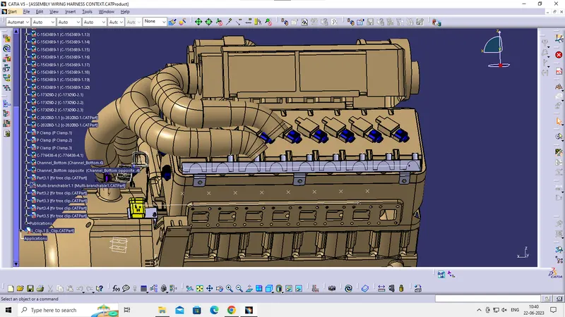
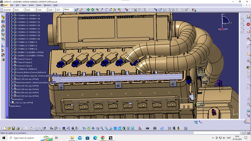
Step7-Engine with all mounting and guiding provisions
The image below shows all the 20 connectors, 2 plastic guiding channels, 3 p-clamps, and an interconnection connector mounted on the sheet- metal bracket.
Step8- Bundel routing
At this stage, we are not using the excat value for bundel diameter. we will assign the bundel diameter values at a later stage. the bend ratio is assumed to be 1.4.
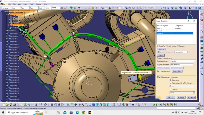
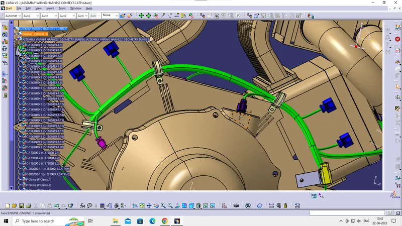
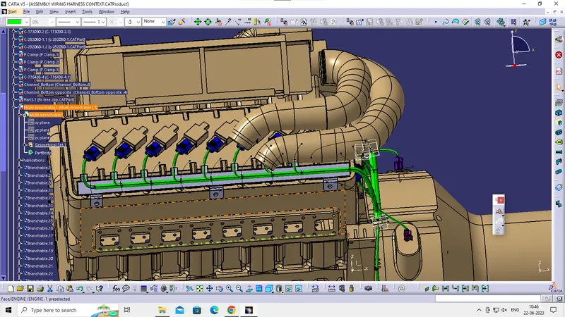
Another branch point is added at 55mm from the interconnection connector. From this branch point, the bundle is routed to the right side guiding channel. it can be noticed that there is no need of any additional mounting provisions for this bundle segment as the bundel path is practical and completely possible in threal world situation.
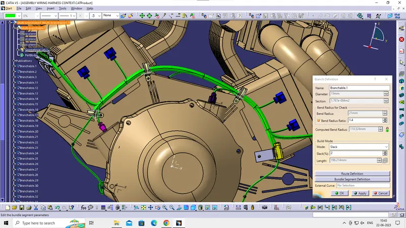
Step9- Definig bundel segment inside the guiding channel
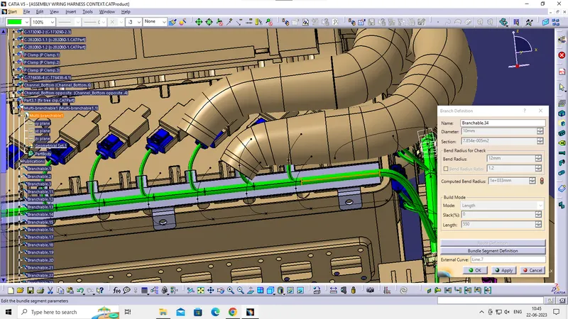
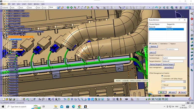
From the entry side of the guiding channel create the first branch point at 100 mm and then subsequently create six branch points at 65 mm.
Route bundle segments from these newly created branch point to the 8 fuel- injectors connectors. Bundle diameter is assumed to be 1.5mm
similarly, route bundle to the left side.
Step10- Checking bundle continuity.
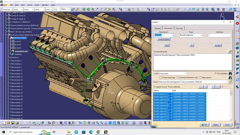
First, we have to make sure that multi- branchable is seleced and then we have to go in
Selecting the TRUE option will show all the connected bundle segmants while the selecting FLAS will show all the non connected bundle segments.
For now we will select TRUE and saerch for results. all the bundle segments are highlighted and found showing that all the bundle segments are electrically connected.
Step11- Creating flat pattern of wiring haarness bundle
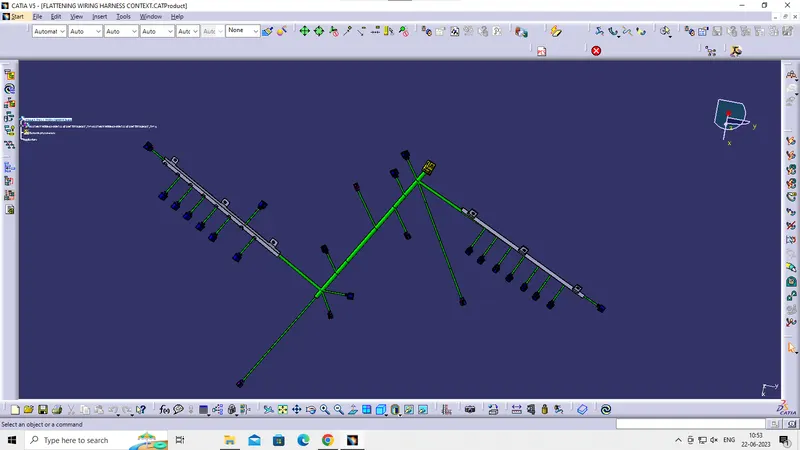
To make a flattened view of any wiring harness we should be working in the electrical harness flattening workbench of CATIA V5. We should also make sure that the flattening file is saved in the same folder where we have all the parts of harness assembly.
Extract and bring the bundel assembly in to the engine harness flattening product file and then flatten the file along the plane
At this stage, for clarity, the flattening diagrame of the plastic guiding channels has been hidden from the drawing view. the drawings for the guiding channel wil be provided separately from the flattening diagram of the harness bundle assembly. The drawings posted above in step-6 have to be used with the wiring harness flatten-view drawing.
For a better representation, we can use some feature like bend, roll to streamline the harness. At this stage, fake scaling can be done for few bundle segments if needed.
Step12- Creating a flatten-drawing view for the wiring harn ess assembly.
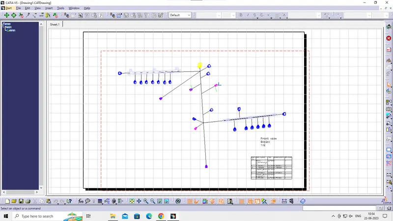
make a new drawing file and define all the necessary drawing parameters, insert the front-view of the harness assembly in to the drawing file.
Define the drawing properties as shown below. it should be noted that for the dress-up settings 3D wireframe is always ON. if this setting is not selected then the bundle segments will not be visible on the drawing view.
Final drawing of the flatten-view of the engine wiring harness assembly.
CONCLUSION-
Routing of the wiring harness for the bugatti v16 engine assembly was done and the flatten-view drawing was prepared in CATIA V5. The drawings posted above in STEP-6 for the left and right guiding channels have to be used with the wiring harness flatten-view drawing. various packaging rules and constraints were considered while routing the harness. industry best practices were implemented in the harness design. All necessarydetails like clearance/ clamping selection, haraness fixing requirements, harness continuity were provided in oreder to design the wiring harness.