Project 1
Aim
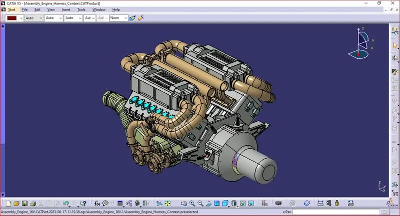
To Route the Wiring harness on given Engine and Prepare flatten view drawing in CATIA V5.
Introduction
Wiring Harness
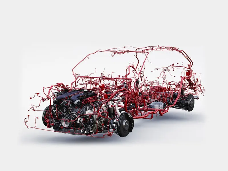
A wiring harness, also known as a cable harness or wiring loom, is a collection of wires, connectors, and other electrical components assembled together to form a complete electrical system. It is typically used to transmit electrical signals and power between different components in a vehicle or machinery.
Wiring harnesses are designed to provide a reliable and secure connection between various electrical components, while minimizing the risk of electrical interference or signal loss. They can vary in size and complexity depending on the application, ranging from simple assemblies with only a few wires to complex harnesses with hundreds or even thousands of wires.
Engine Wiring Harness
An engine wiring harness is a specific type of wiring harness that is designed to provide electrical connections and transmission of signals within the engine compartment of a vehicle. It is responsible for connecting various electrical components of the engine, such as sensors, actuators, ignition coils, fuel injectors, and the engine control unit (ECU).
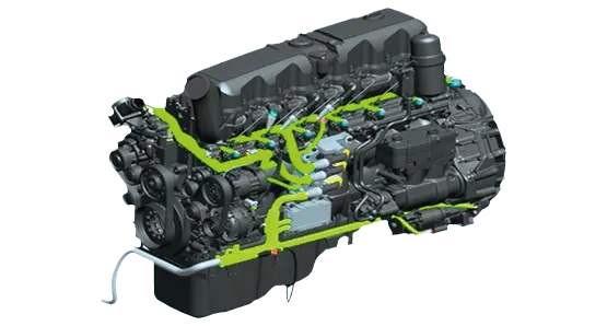
The engine wiring harness is typically made up of multiple wires and connectors that are specifically tailored to the requirements of the engine and its associated components. It is designed to withstand the high temperatures, vibrations, and environmental conditions found within the engine compartment.
The engine wiring harness plays a critical role in the proper functioning of the engine, as it enables the communication and control of various electrical systems within the engine. Any damage or malfunction in the wiring harness can lead to electrical issues, engine performance problems, and potentially even engine failure.
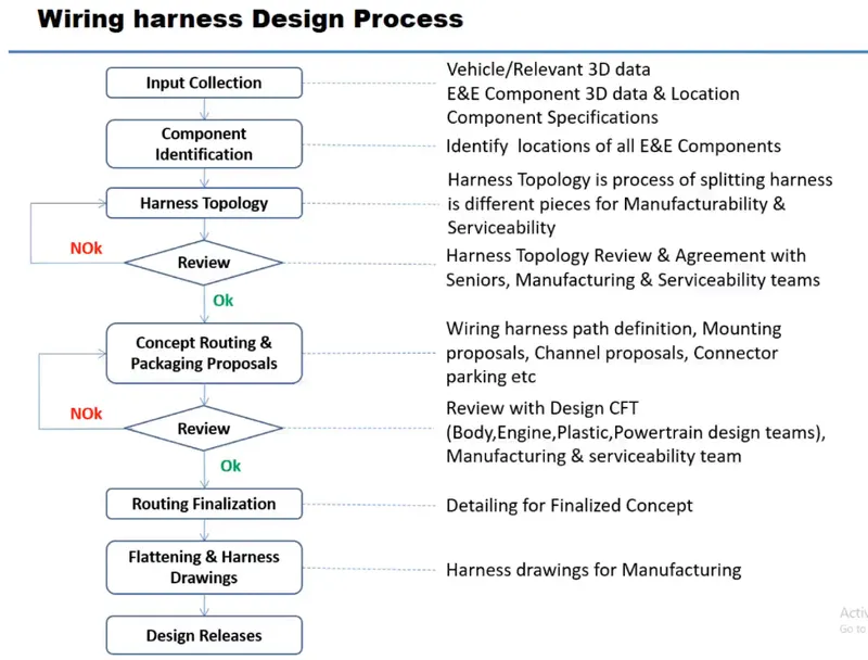
Wiring Harness Design Process
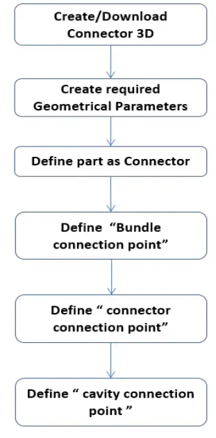
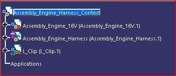
Wiring harness Assembly Structure – Connector Definition
Flattening
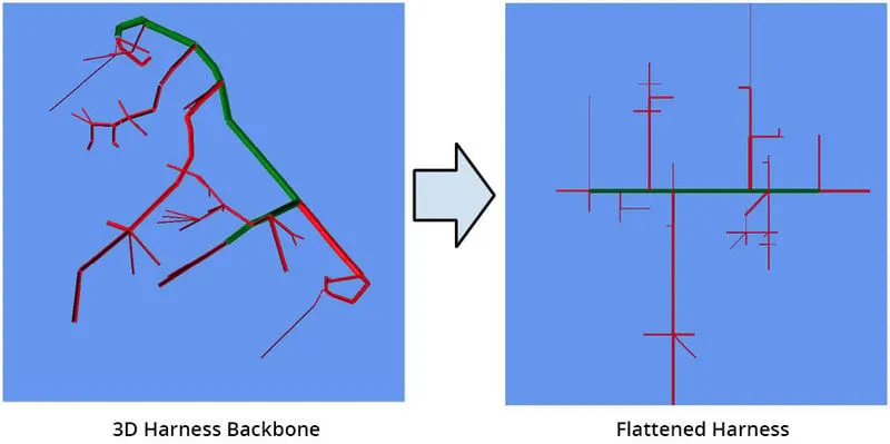
"Flattening" in the context of a wiring harness refers to the process of removing any twists, kinks, or bends in the wires and cables of the harness to create a flat and organized configuration. This is typically done to ensure proper routing, prevent interference, and optimize space utilization.
During the manufacturing or installation of a wiring harness, the wires and cables are often bundled together and secured with various fasteners, such as tape, zip ties, or clips. Over time, these bundles may become twisted or bent, which can affect the performance and reliability of the electrical connections.
Procedure
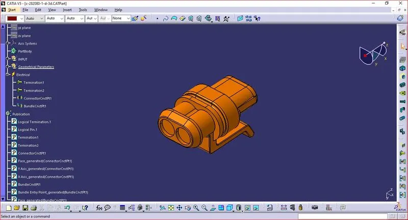
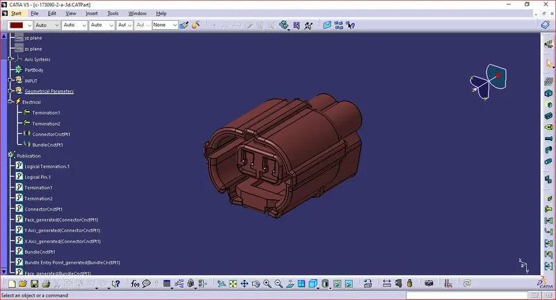
Step 1: Collect all the required 3D components and define the Parts Electrically.
- Connectors.
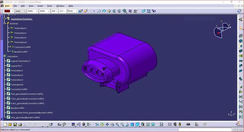
- Creation of connector connection point
- Make a midpoint on the contact face for wire bundle insertion.
- Create an axis system referencing the newly generated point and specifying the axis direction.
- The Y-Axis should be oriented towards the connector's front face.
- The X-Axis should be oriented towards the clip's locking mechanism.
- The Z-axis should be pointing across the connector from left to right.
- Creation of Bundle Connection Point.
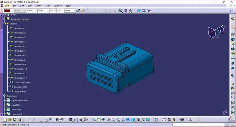
- Define the part as a connector and specify terminations.
- Define Bundle connection point.
- Define connector connection point.
- Define Cavity connection Point Optional.
- Clamps, Clips
- Add two points. Both as points of admission and exit.
- Create two planes, plus one at the base.
- Change the part design to electric
- Click on support definition, then part selection, entry point selection, entry plane selection, and base plane selection.
- Again click on support definition, and then select part, select exit point, select exit plane, with the base plane being automatically taken as the secondary plane.
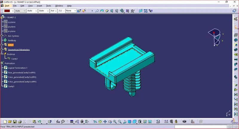
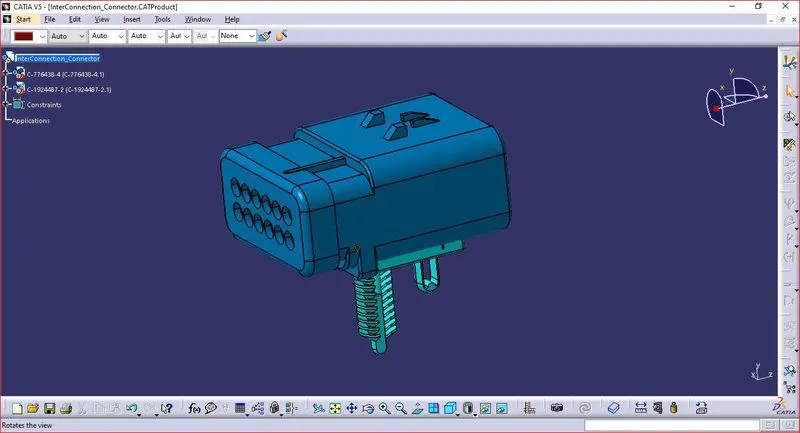
- Assembling interconnection Connector and Cavity.
- Plastic channel
- To create the multi-branch capability utilising an external curve inside the channel, draw a line curve connecting the primary entry and exit locations.
- On the apertures where the injector connectors will be connected, create 8 bundle entrance points.
- Use the define mounting equipment option to define the channel electrical based on the geometrical specifications.
- Use the "define bundle connection point option" to define bundle entry points.
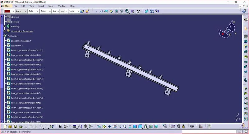
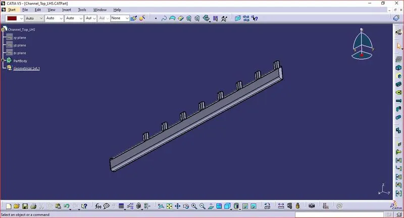
- Assembling top and bottom part of plastic channel.
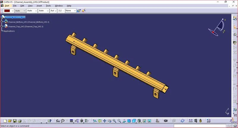
Step 2: Location of all components.
- Adding connectors to the all 16 fuel injector sensors and 4 cam-shaft sensors.
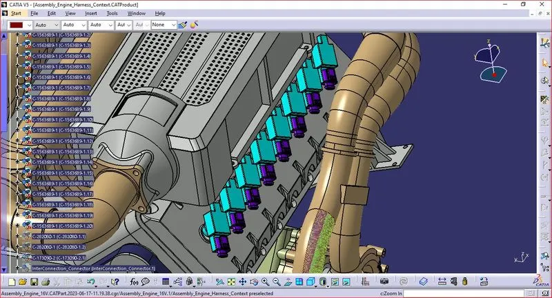
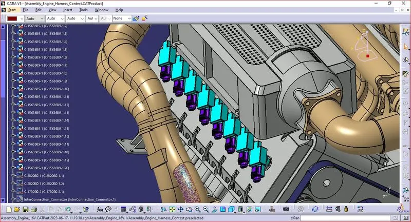
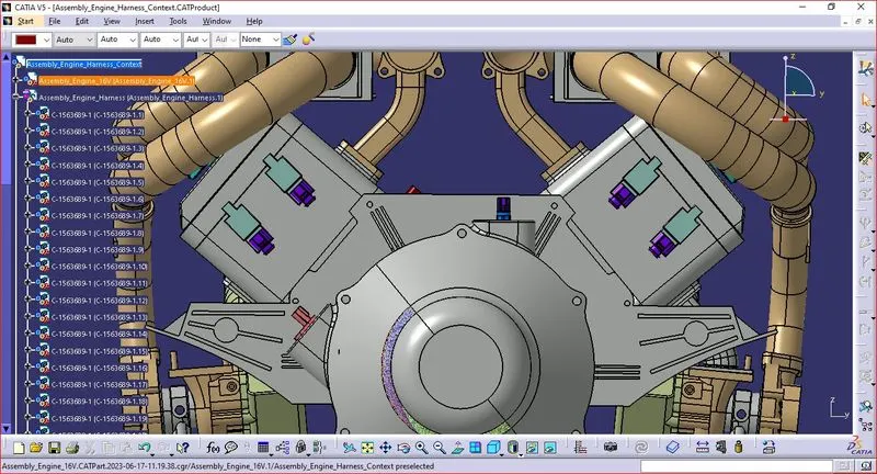
- Adding sheet metal bracket
In order to provide mounting for the interface connector, we must install a sheet metal bracket. Additionally, we must ensure that the bracket is positioned outside of the engine and geometrical bundle assemblies and inside the context assembly.
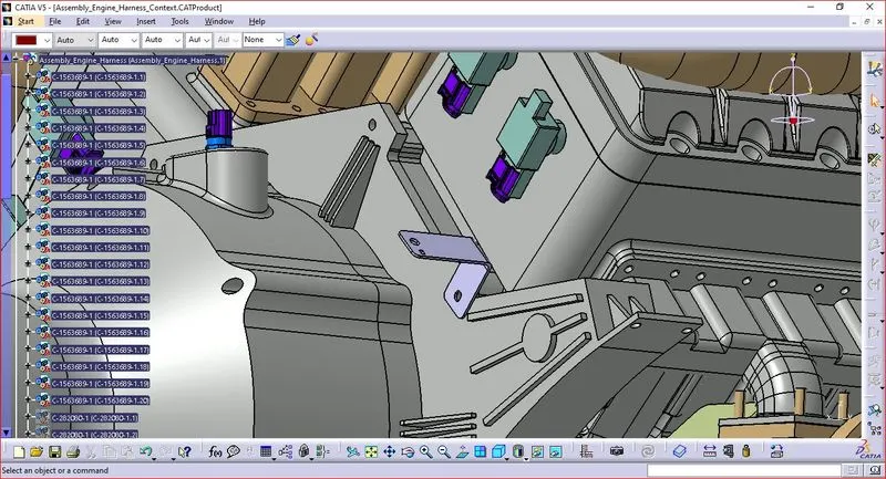
- Mounting the electrically connected interconnection connector and cavity on sheet metal bracket.
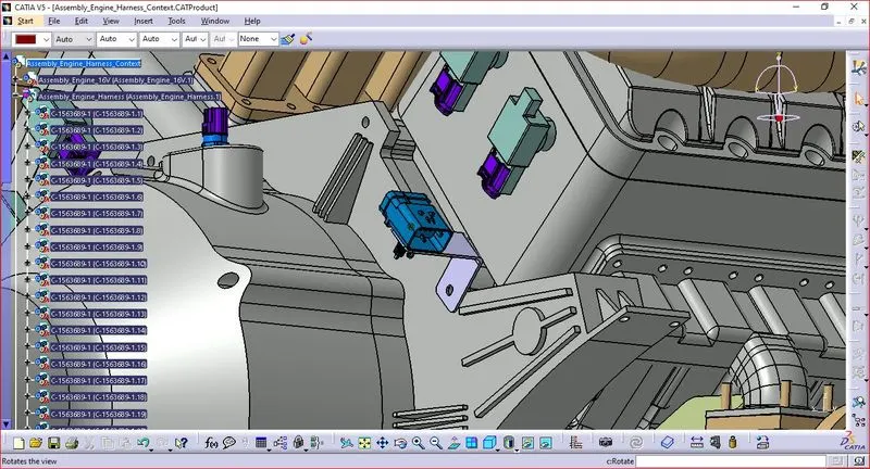
- Adding Connection of 2 pole connectors.
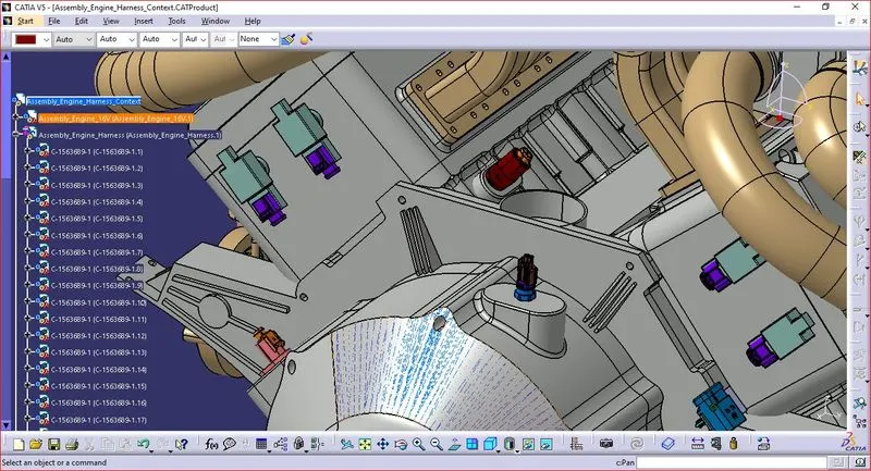
- Mounting of electrically define the plastic channel
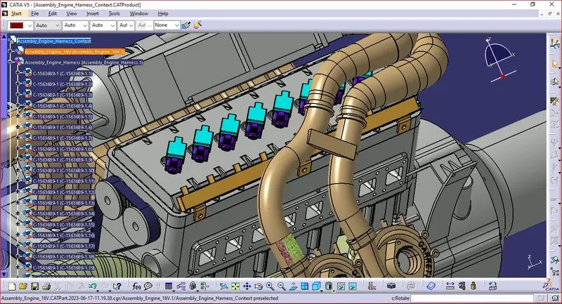
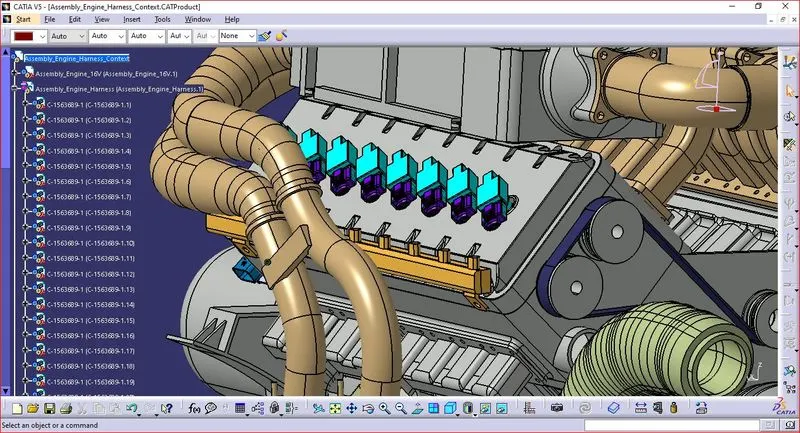
- Arrangement of 3 P clampsfor bundle routing from interconnection connector.
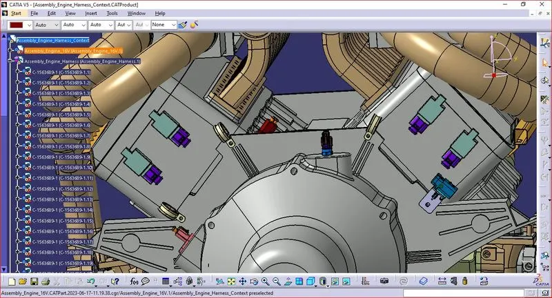
- The Assembly is ready for routing.
Step 3: Harness Routing.
- Define Product File as Geometrical Bundle.
- Rout the Electrically defined components with Multi-Branching.
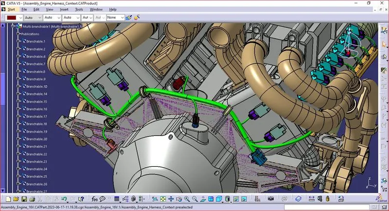
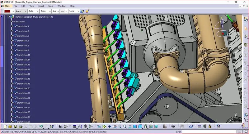
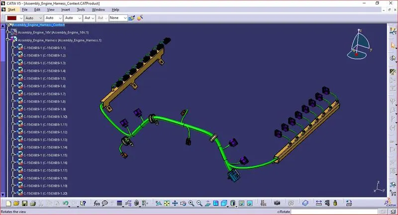
Step 4: Checking the Bundle continuity.
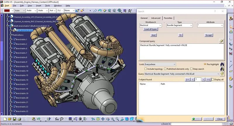
- Make sure multi-branchable is first chosen, then proceed to Edit > Search > Advanced > Workbench > Electrical > Type > Bundle Segment > Attribute > Fully Connected.
- The 'True' option will display all linked bundle segments, whereas the 'False' option will display all disconnected bundle segments.
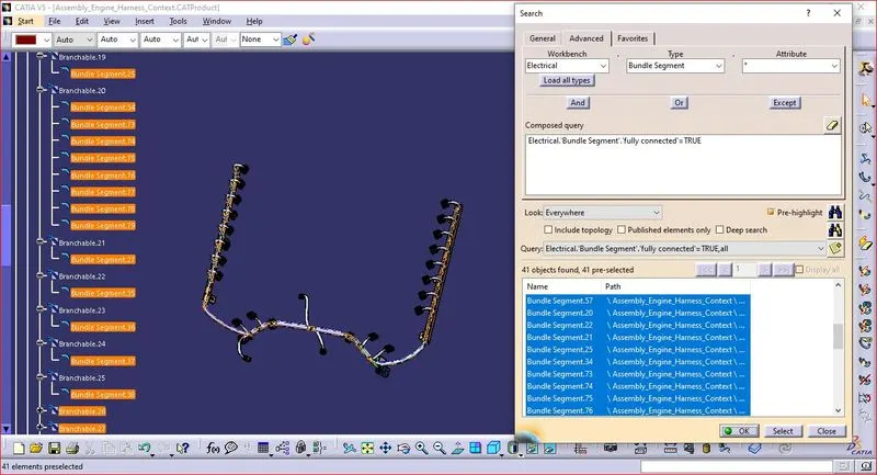
- In this case, we chose the 'True' option and ran a search.
- As illustrated in the below image, all of the bundle segments are highlighted to show that they are all electrically connected.
Step 5: Adding protective coverings.
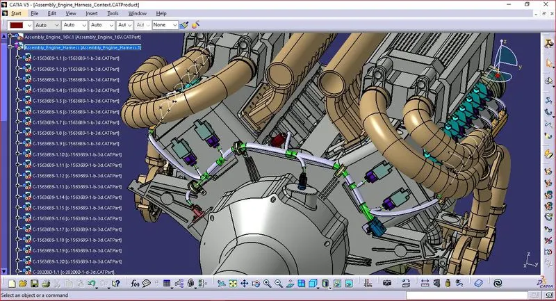
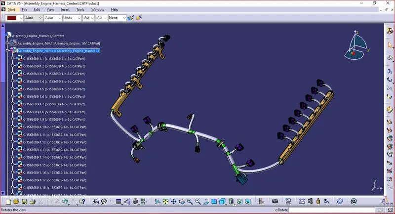
For the V16 Engine, we completed the entire wiring harness layout. The top shell of the guiding channel as well as all bundle segments must now be covered with protective materials.
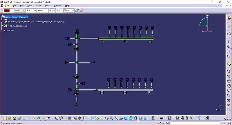
Step 6: Harness Flattening
- Define the "Flattening Parameters" in harness flattening Workbench.
- Extract the Harness assembly to the Harness Flattening Workbench.
- The parts are assembled in a proper way that they are easily visible.
Step 7: Harness Drawing
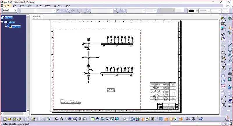
- Make a drawing file for the harness product that has been flattened.
- First, we must ensure that bundles and protective covers have distinct graphical representations in the flatten parameter settings
- Single-line illustration of bundle segments
- Coverings used as protection - Double line illustration.
Conclusion
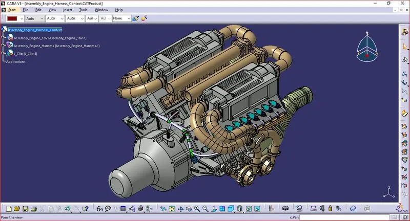
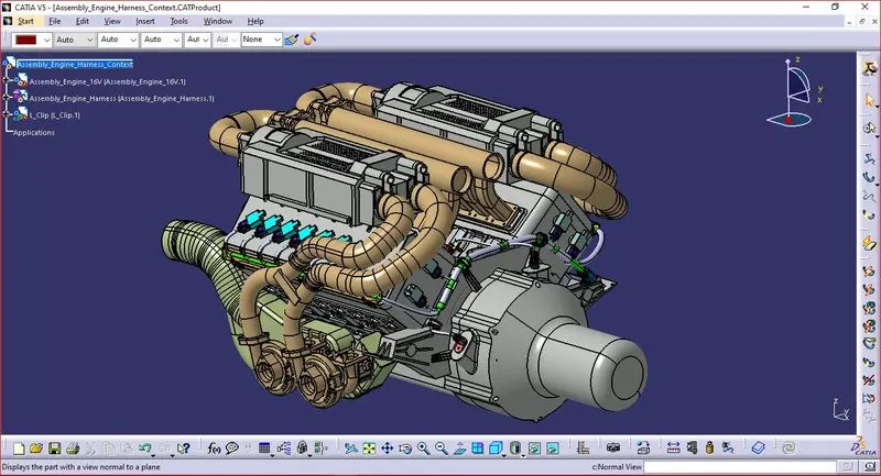
Thus the Wiring Harness Routing on the given V16 Engine is routed and flattens view drawing is created using CATIA V5.