Project 1
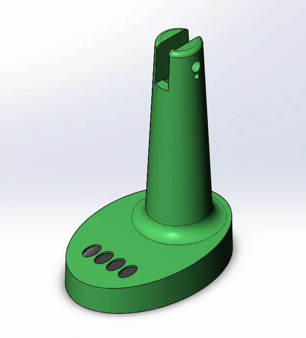
CREATION OF MOLD FOR A TABLE FAN OUTER CASING
INTRODUCTION
Molding is a process in which a molten or liquid material is poured into a mold and allowed to set or freeze. There are many types of molding process out of which injection molding is widely used. Injection Molding is a manufacturing process for producing parts in large volume. It is most typically used in mass-production processes.
Injection molding is a manufacturing process for producing parts by injecting molten material into a mold. Molded products are obtained by injecting plastic material molten by heat into a mold and then cooling and solidifying them.
OBJECTIVE
To create a proper mold for the fan outer casing with ejectors and sliders if needed. Assuming the material to be ABS.
METHODOLOGY
Step 1- Decide a tooling direction and do a draft analysis and decide the core and cavity side.
Step 2- Increase the size of the model to account for the shrinkage.
Step 3- Create a parting line on the core cavity separation.
Step 4- Create a shut off surface.
Step 5- Create a parting surface.
Step 6- Core and cavity surfaces are created.
Step 7- Create a core and cavity blocks.
DESCRIPTION
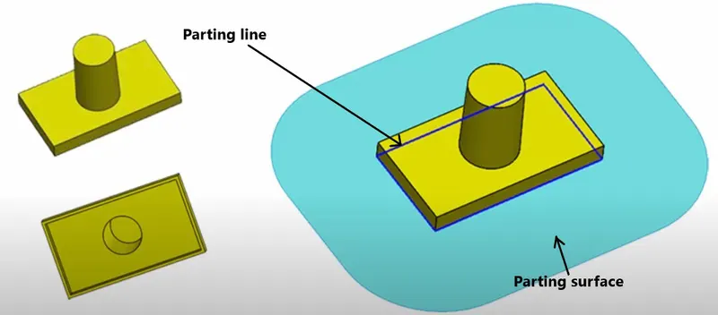
Parting line-
A 'parting line' is the line of separation on the plastic part where the two halves of the plastic injection mold meet.
Parting surface-
A parting surface is a surface that separates the mold block into two parts – the core and the cavity.
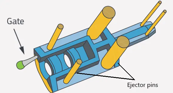
Ejector pins-
Ejector pins apply a force to eject a part from the mold, and in some cases can leave marks. Once the mold is opened, the pins extend into the mold cavity, push the part out, and then retract, allowing the mold to close and be refilled.
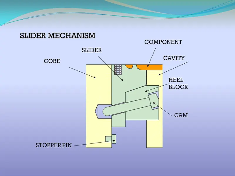
Sliders and Cams-
Sliders and cams are moving parts within the mold that allow or restrict access to particular areas within the tooling (and thus facilitate the desired shape of the part). The use of sliders or cams can facilitate ejection of certain areas of plastic that might otherwise be trapped in the tooling.
Steps for making the core and cavity block-
1.
Decide the tooling direction and then do the draft analysis. Usually the draft angle of 0.5º is given.
Then decide the core and cavity side.
While deciding the core and cavity side we also see the number of ribs or any feature on both side and the side which has more number of features is taken as the core side and the other side and the cavity side.
This is done because the core side has ejector pins, so we eject the component easily without it getting stuck.
2.
Use the scale command to increase the size of the model to account for the shrinkage.
Here the material used is ABS and the shrinkage percentage for ABS is 0.6%
So, we will make the model 1.006 times bigger than the model given to us.
3.
We need to close or fill the surface for creating the core and cavity block. Use the shut off surface command to fill the holes.
4.
Use the parting line command to create the line on the core and cavity separation.
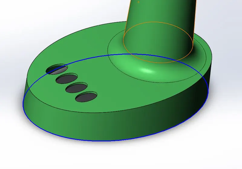
5.
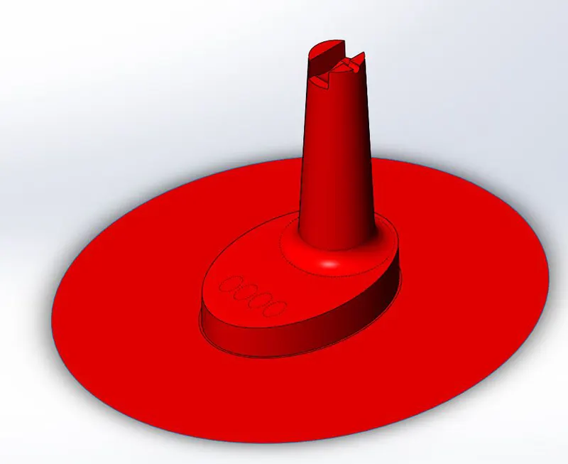
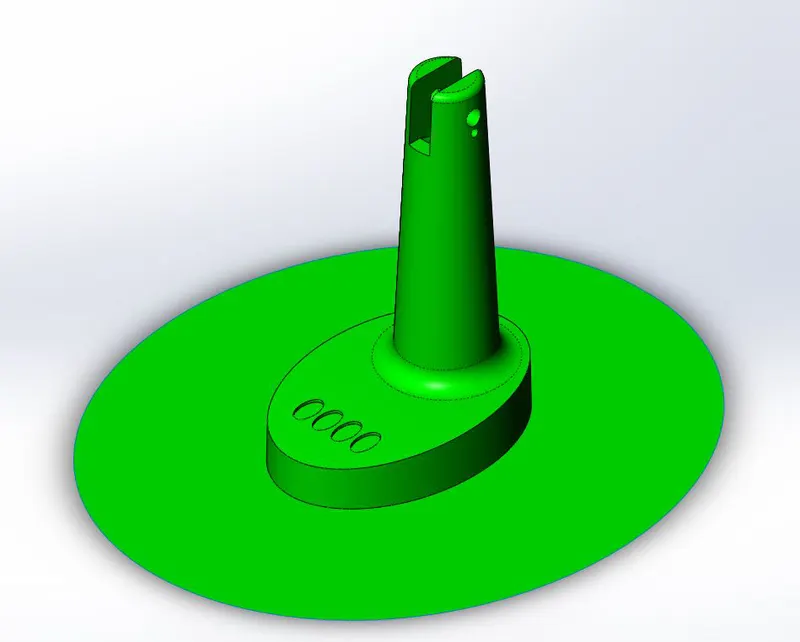
For the parting surface we use the parting surface command to create a surface.
6.
Create the core and cavity surface. Use the move/copy bodies tools to copy the parting surface and the knit one of the surfaces with the surface body for the core and the other surface with the surface body for the cavity. By doing this two surface gets created for the core and cavity mold.
7.
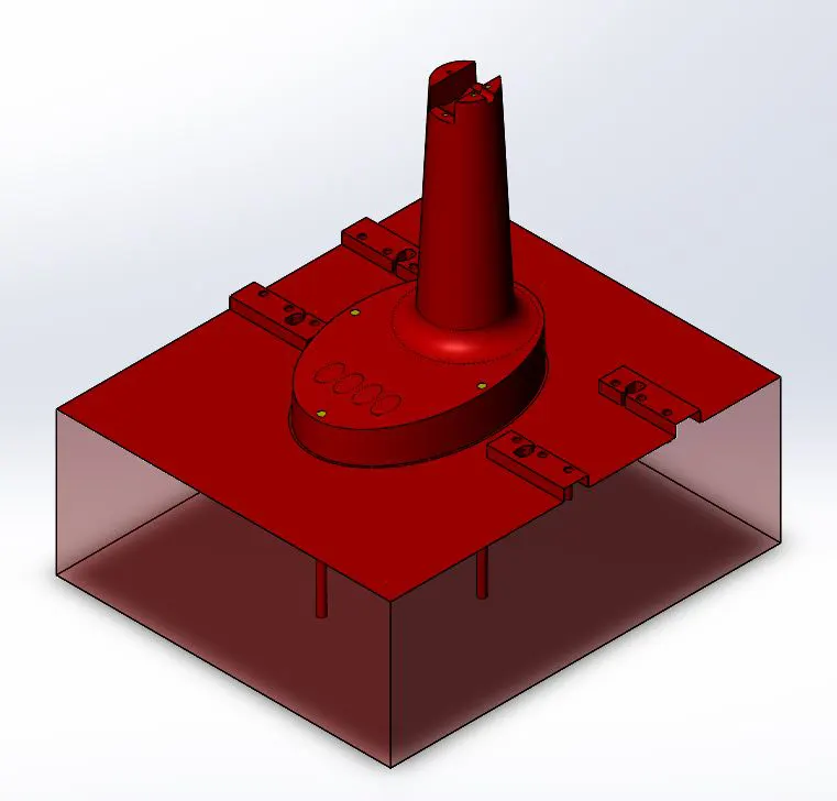
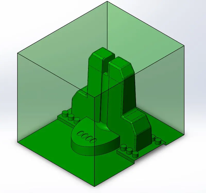
The width of the mold depends on the size of the ejector plates. Besides the ejector plate there is also the spacer blocks the standard size of the spacer block is 45mm. Also we add 50mm more in the width for the bottom support. Considering the sprue at the centre the mould is designed.
The length should be atleast 50 mm distance from the component.
The thickness of the block depends upon the cooling channels. The distance between the cooling channel and core block is kept at 40mm. The thickness is considered from the top most part of the block to the bottom flat base of the block.
8.
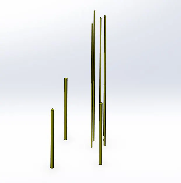
Create ejectors pins. Create a sketch for the ejector pin. Pin ejector system of type 1 is created. Pins are generally placed near the ribs and sidewalls.
There should be minimum distance of 1 mm between the pin and outer boundary.
Use the core tool to create the ejector pin and also the surface for the ejector pin in the core block.
Relief is provided from a distance of 10mm onwards. Use the extrude cut option to remove the surface for the relief.
9.
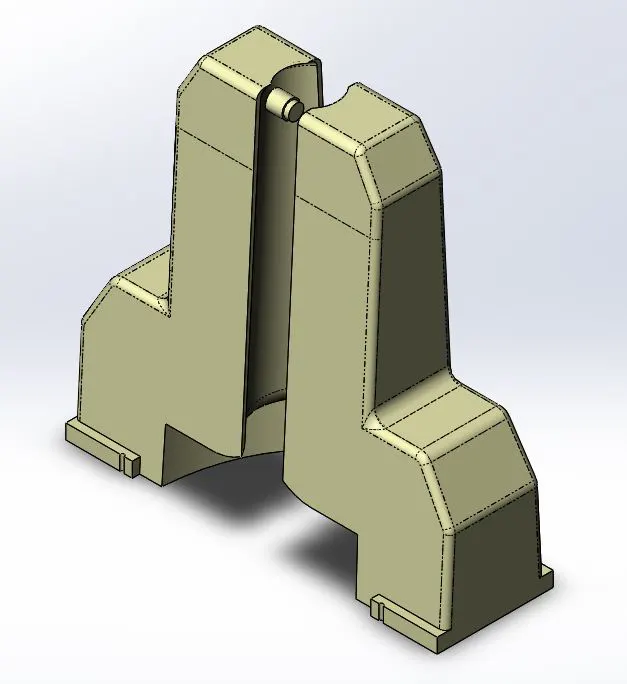
In this step sliders are dsigned. The slot for which the slider is required is in the cavity area. So first we edit the cavity region. Use the sketch tool to sketch that region and then make a reference along that. Then use the split command to split the body so that we get a body of the slider as well as that of the cavity. Then we edit the slider in such a way that it fills all the gap and the mold can be formed.
The width of the slider should be such that it accommodates the finger cam and the washer. The standard diameter of a finger cam is 16mm. A wedge is provided on the slider so that it can interlock with the cavity block.
Height should be 2/3rd and angle is taken as 30º.
Then fill up the remaining gap using sketch and extrude command and for giving the cavity the shape of the slide, make a copy of the slider bodies and then use the combine command, in that select subtract option to subtract the copy of slider body with the main body.
In the assembly file insert a new component for the slider and import the solid body of the slider which was saved. Then using the save combine command edir the core block and fill the remaining gap.
10.
In this step we make the guide rails for the slider to move. The guide rail should have enough width to fit the washer. Create the guide rail in the core block using extrude command. Now since the guide rail was made in the core block, make cavity for the guide rail in the cavity block.
11.
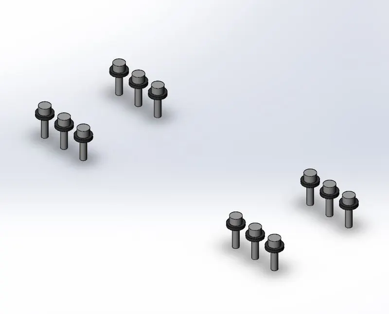
In the assembly file create a new part for the washers. Draw the sketch for the washer with diameter od 16mm and then extrude it. Then we create a bolt to and then use sketch driven pattern to copy it along the slider and washers.
Use the hole wizard to create a tapped hole on the core block.
After creating this, edit the cavity block too to create a cavity for the washer and the bolt.
12.
Locking mechanism is created on the core block. Create sketch on the core mold for the locking mechanism and the use the cut extrude command to cut from the core mould. Then travel distance pf the slider is taken as 15mm, so while creating the slot for the slider it then made at a distance of 15mm from the slot in the core.
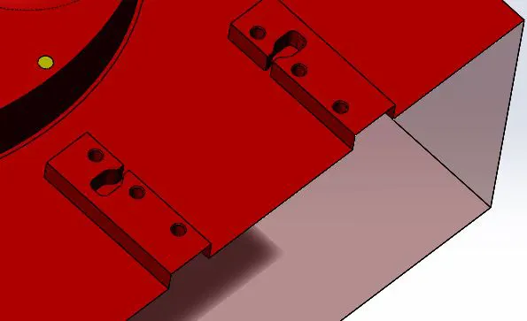
Result-
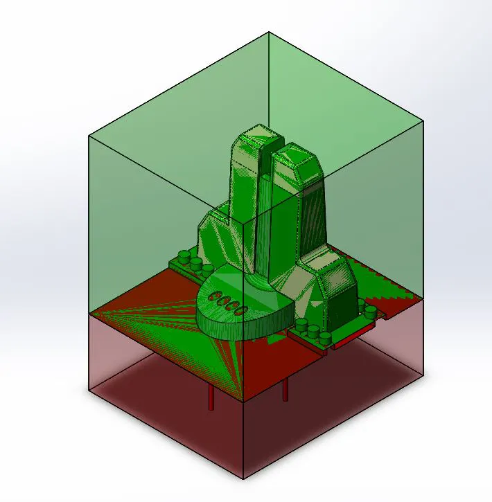
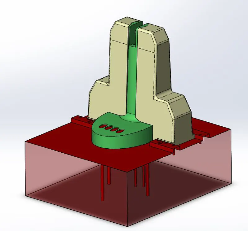
CONCLUSION
With the help of this project we got to learn about procedure and the parameters we need to follow while designing a mold for the component.