Project 1
WIRING HARNESS OF THE ENGINE
AIM: To provide the wiring hareness of the given engine file making the proper routing of the bundle segments through out the engine components and cresate the flattening of the harness generated along woith the drawing representation
Objective :
The main objective of the project is to route the bundle segments for the engine by packing the proper clippings and the clampings and using the proper connectors for the witring harness assembly
The process follows the
- Download the required input file of the engine
- Apply the wiring harnesss topology strategy for proper routing of the bundle segments
- Input the proper connectors, clamps, clips
- Define the components as electrical
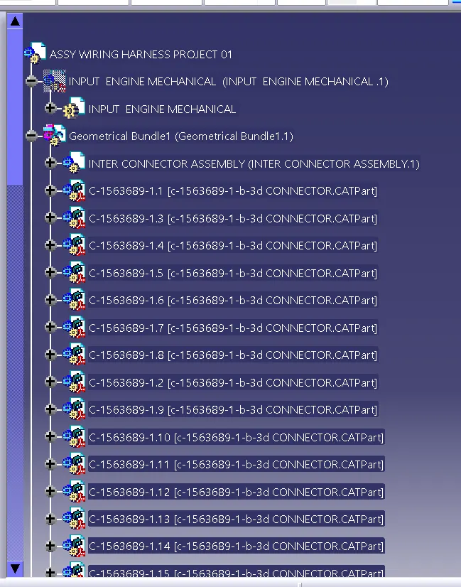
- Assembly all the electrical components in a single geometrical cat product file
- Start routing the bundles
- Apply the protective coverings
- Represent the wiriing harness in the drawing file
- Download the required input file of the engine :
First of all we need to download the engine file required as the input file for the assembly
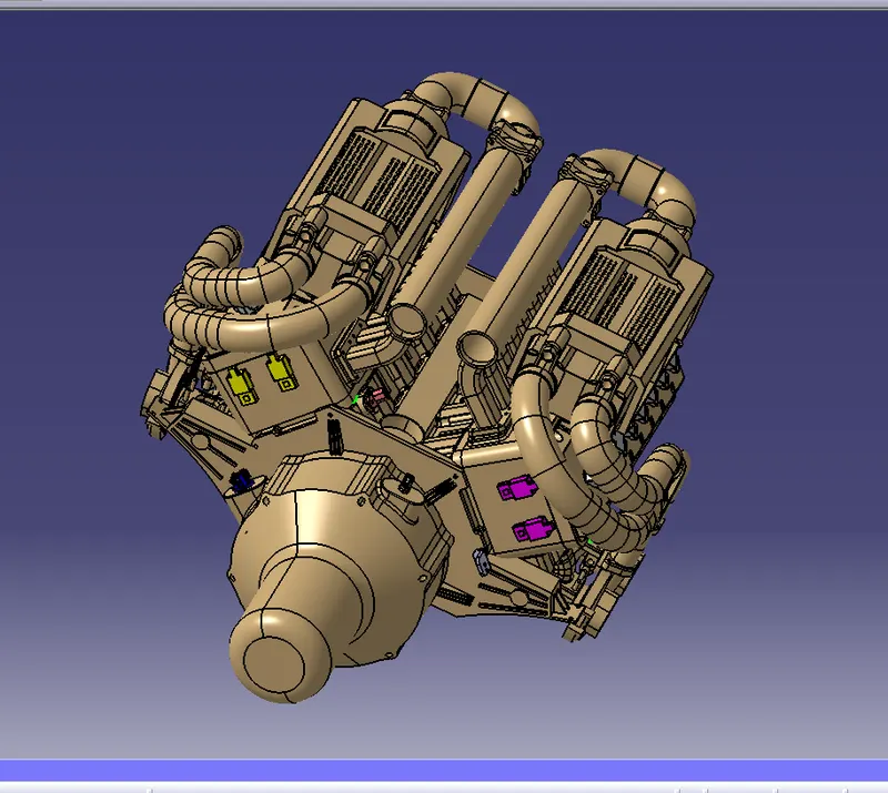
Make a clear examination of the engine and make an idea or the a strategy to route the bundle segments
The connectors we use are the
Basically
connector 01:
The interconnector we use for making the possible connection between the mechanical and the electrical components Define the part as the electrical by providing teh number of terminations
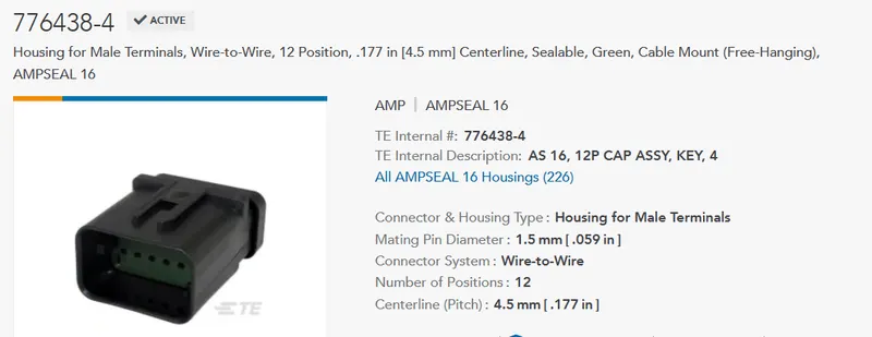
Define the component as the electrical connector
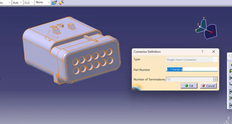
Before making the part as an electrical create the reference elements like the axis system , entry and the exit points for the connector
Then define the coinnector connection system
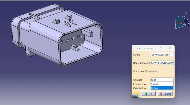
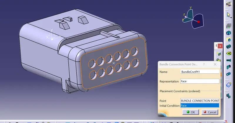
DEfine the bundle connection system
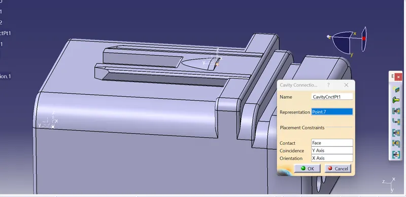
Define the cavity connection point
Then save the file
For the connector to mount on the base plate we design we need to place a mounting equipment on the connector to make a possible assembly with the engine
The mounting equipment is
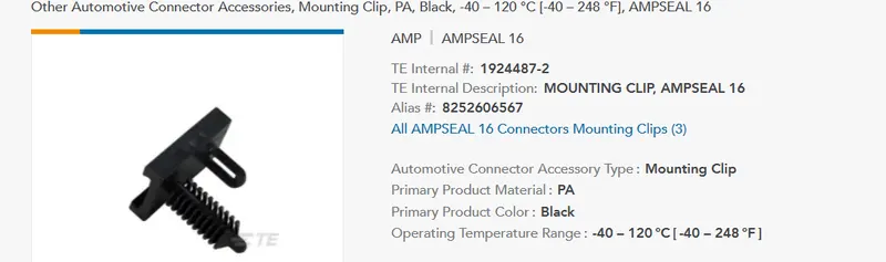
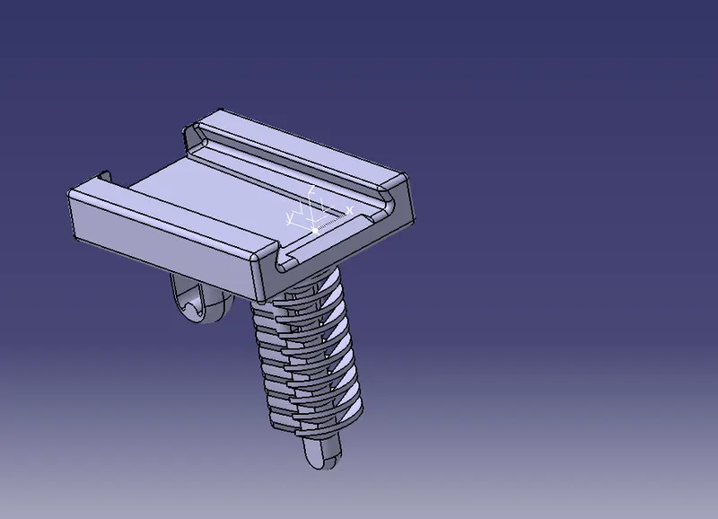
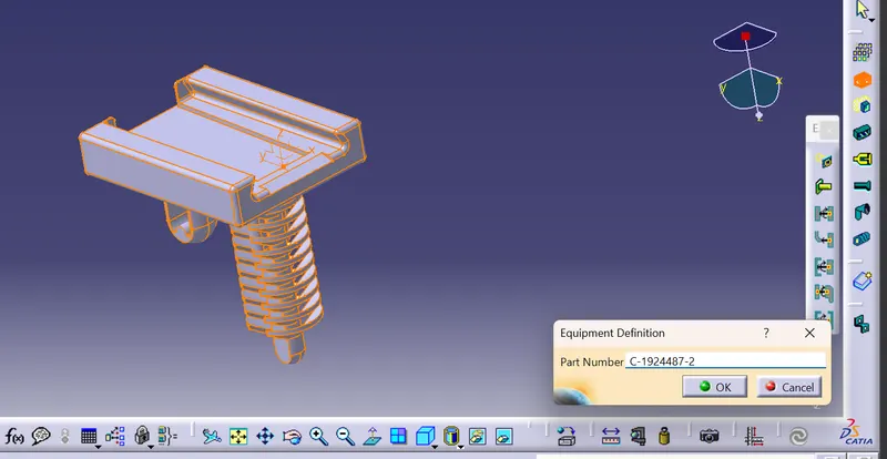
define the partb as an electrical mounting equipment
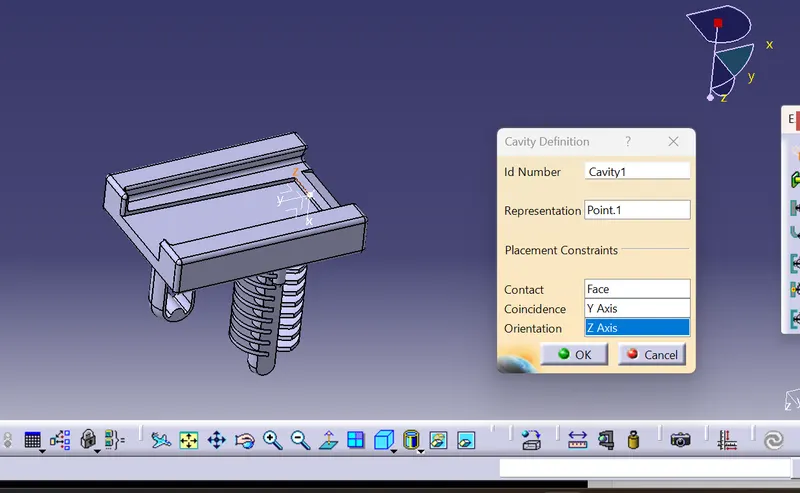
Define the cavity defnition point
then save the file
Then go tgo the assembly wokbench of the wiring harness and connect the two parts uing the connect two devices feature
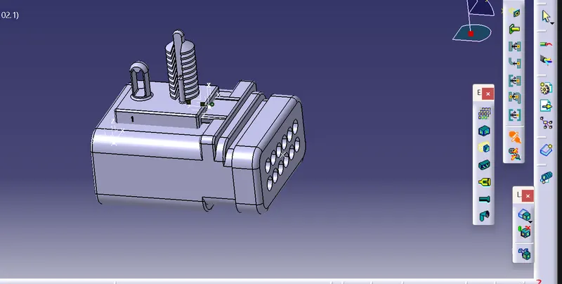
Then the clip is mounted on to the connector so, our connector is ready for the assembly
The other connector we use are the
Connector 01:
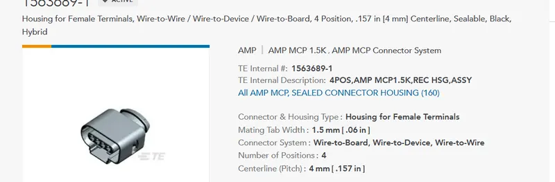
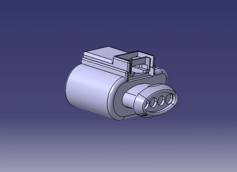
Create the require refernce elements for defining the poart as an electrical component
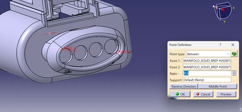
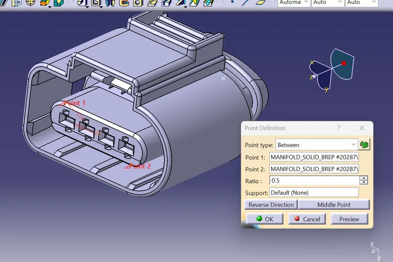
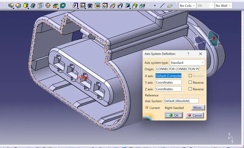
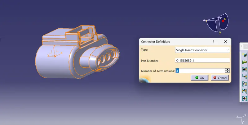
Define the connector as the electrical connector
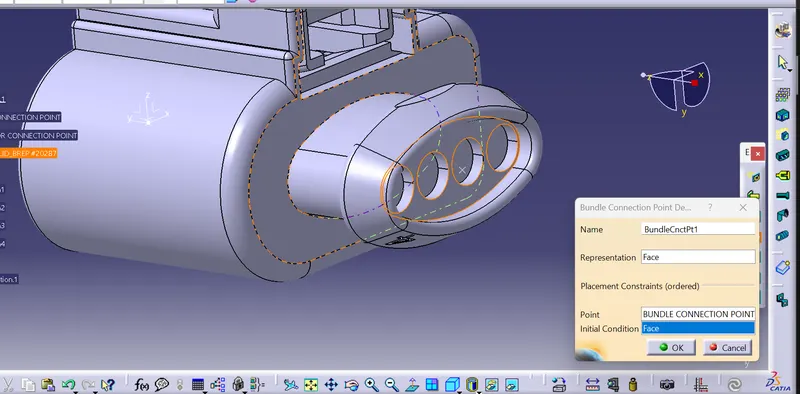
Define the bundle connection point
Define the connector connection point.
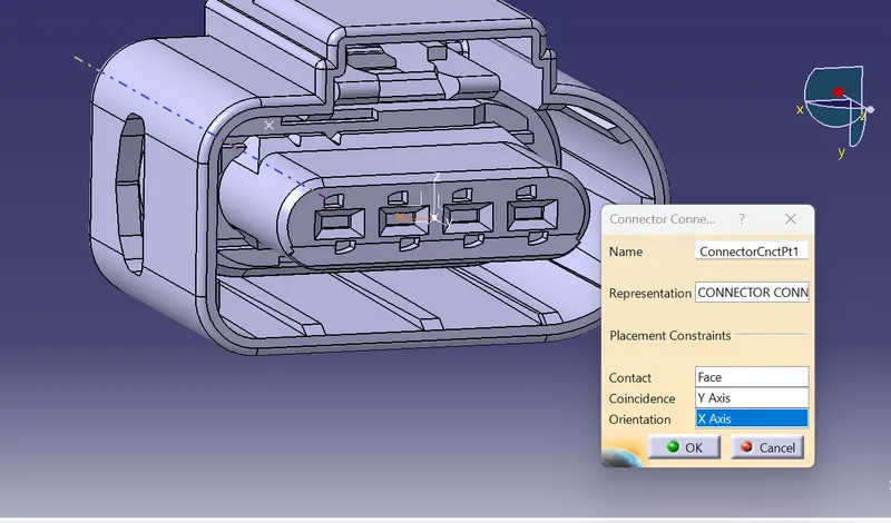
save the component
Connector 03:
The other connector we use for the asswembly are the
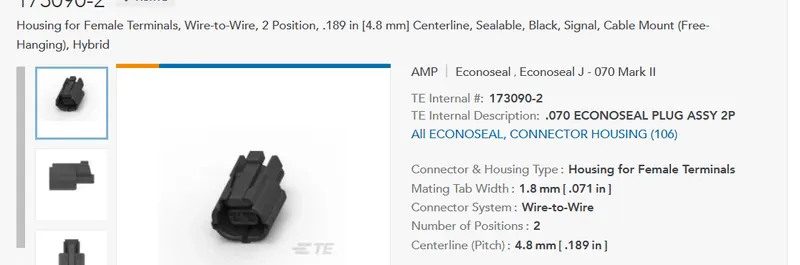
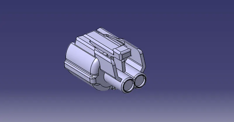
Create the proper freference elements
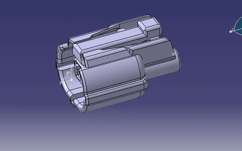
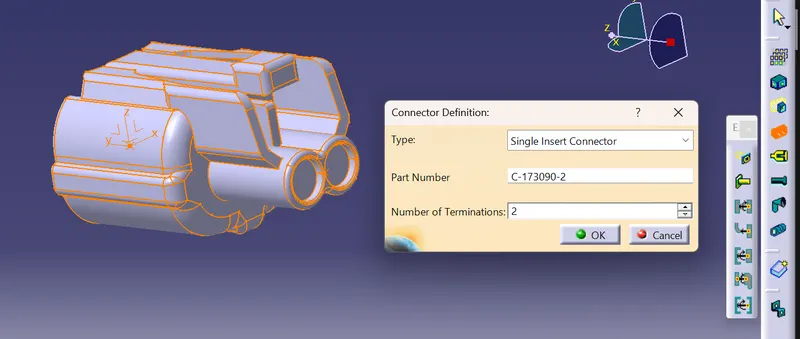
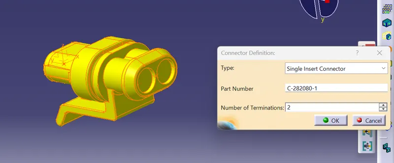
Now defin ethe partsas the electrical connector by providing the number of termination as the 02
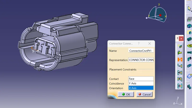
Define the connectorconnection point
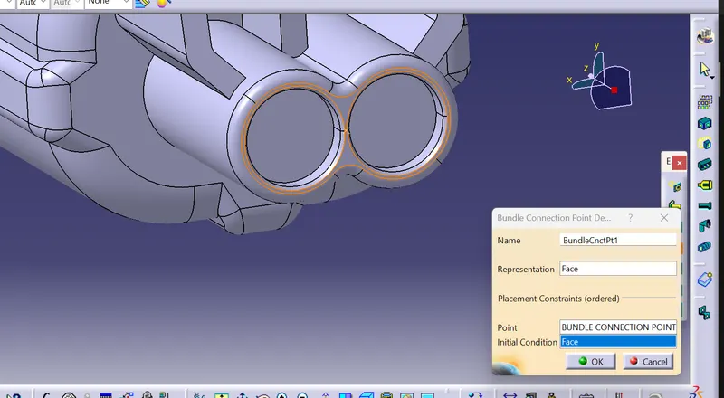
Define the bundle connection point
 .
.
save the electrical component
Connector 04:
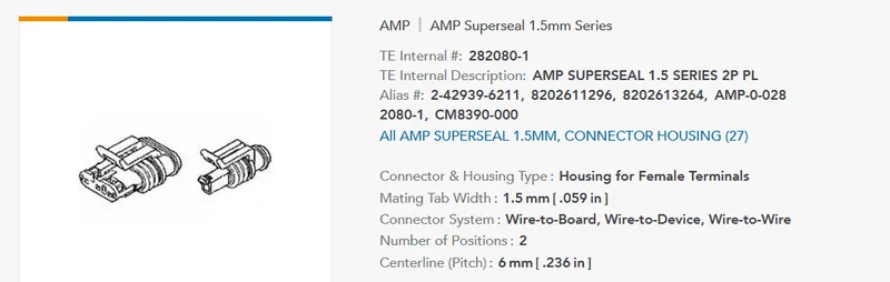
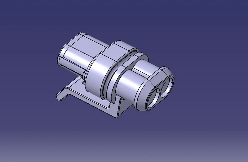
Create the required reference elements
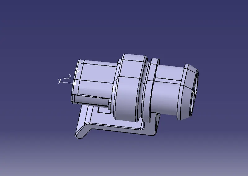
define the part as an electrical connector
.
Define the connecor connection point
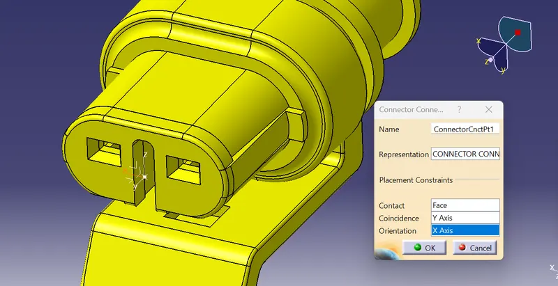
Define the bundle connection point3
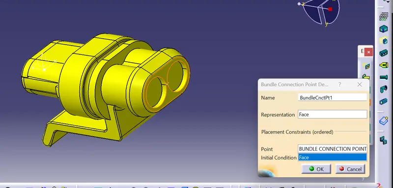
Now the p calmp is
P CLAMP:
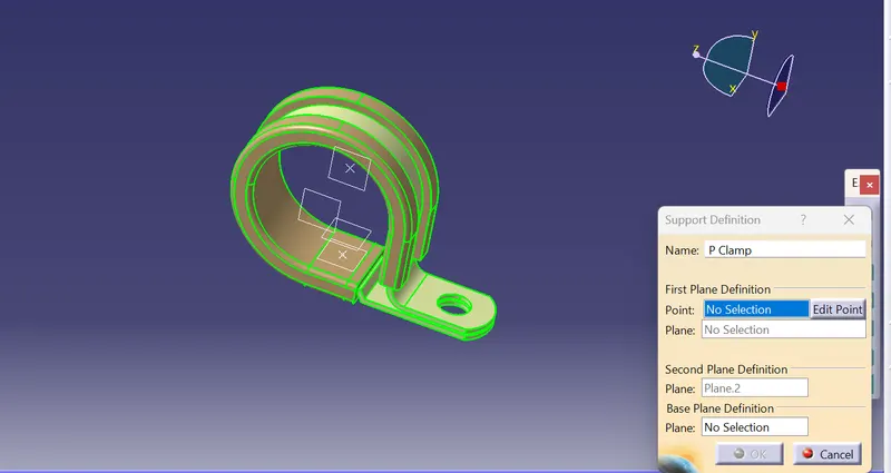
the p clamp generaklly have two entry points and the two exit points so we need the define the p clamp as the support par for two times giving the one entry and alternate exit two times
The other mounting component is firr tree clip
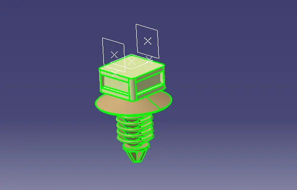
FIRR TREE CLIP:
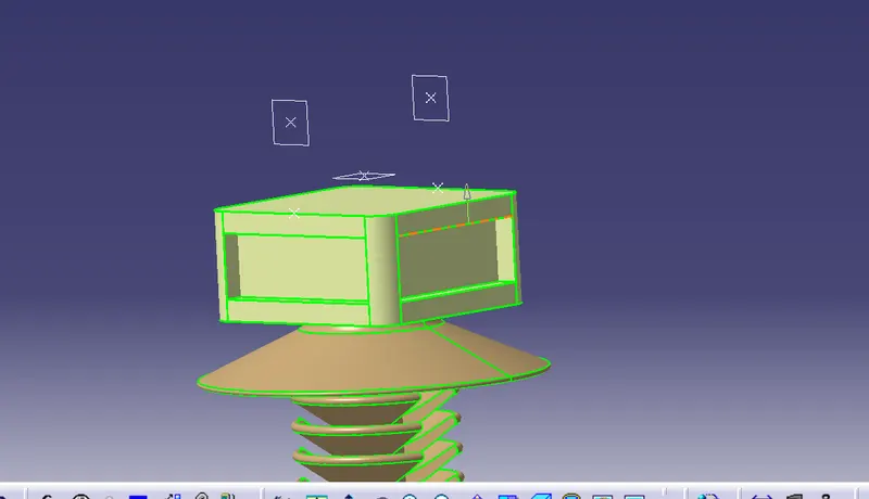
For this also we need the define the firr tree clip with two times providing two entry and two exit points
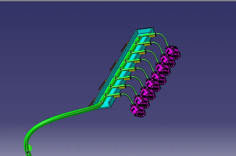
Now we need to create the guiding channels for the routing the bundle segment into the spark ignition connector systems so the guiding channels designis as follows
The design of the guiding channel as follows by measuring the required paramerters that is the length and the width where the guiding channel going to rest 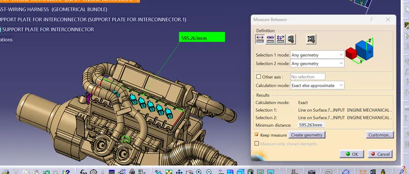
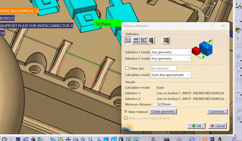
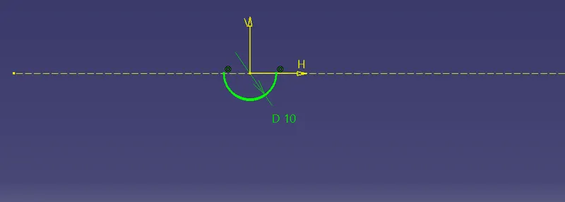
Noew the design as follows
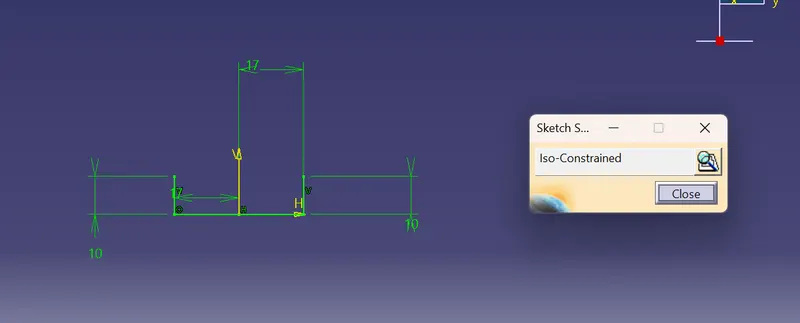
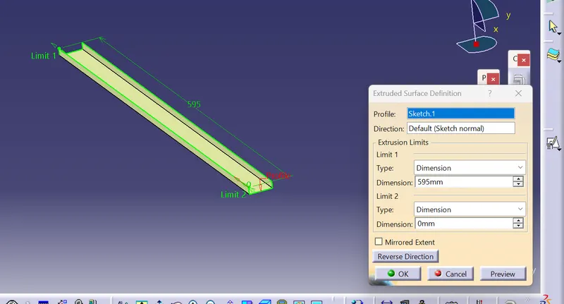
Now thicken the guiding channel to a width of 2.5 mm
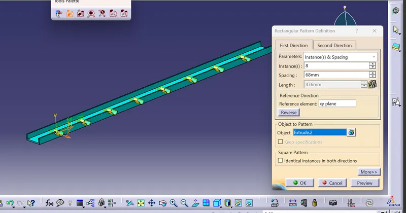
Use the rectangular pattern with a provided distance between the consective bundle segment holes
After that we need to provide the proper fixation supports to rest the guiding chaneel firmly on to the engine assembly so , we design based on the design constrains and inform the design mechanical engineer to oprovide slots for proper fixation onto the engine assembly
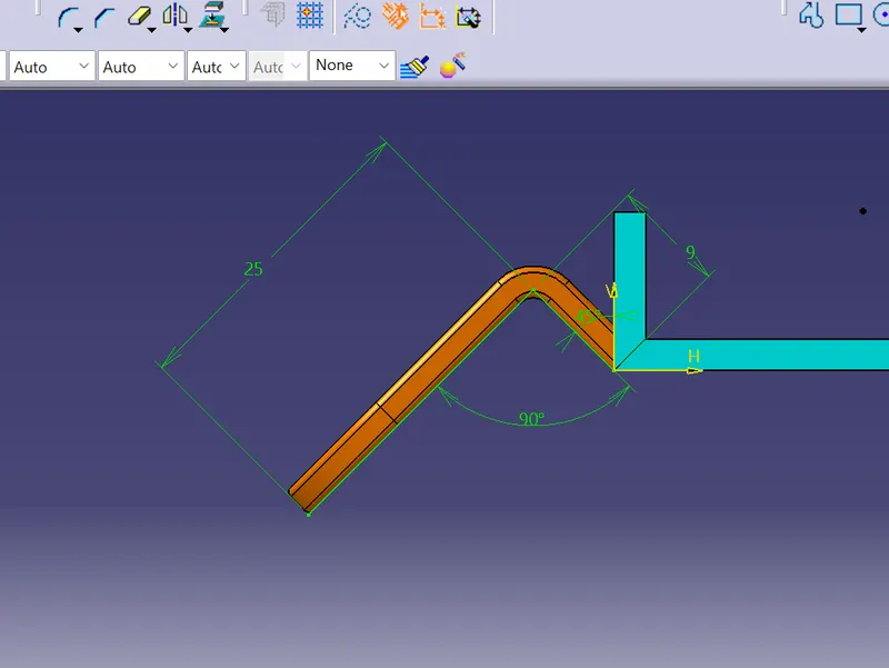
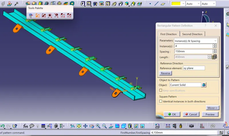
now define the guiding channel as the electrical mounting equipment
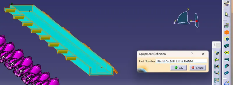
Define the bundle connecttion point
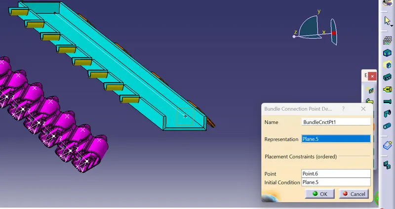
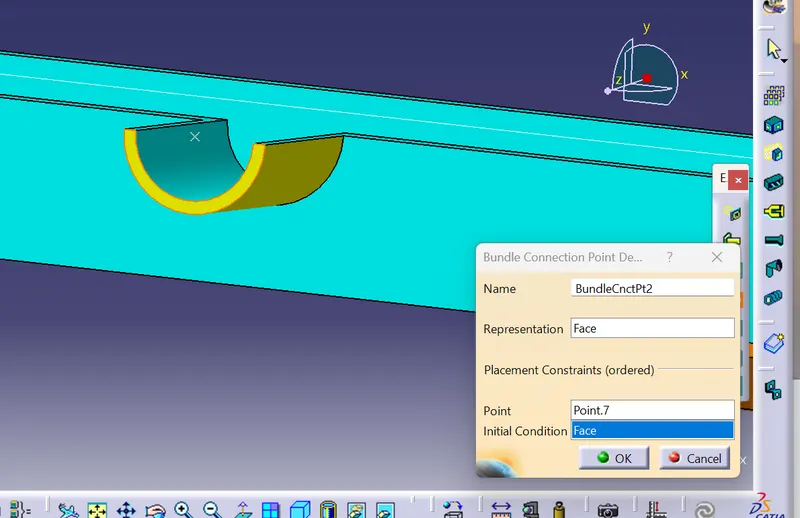
define the bundle connection point for the 9 bundle segment routing holes also
.
Now create a contex assembly the purpose of the context assembly is to
- To create a geometrical bundle where all the electrical components are placed
- The supports parts for the assembly weiring harness are placed
Now align all the electrical connectors the guiding channel , the clamps , the clips by following certain design consideratuions for best routing possible
First align the base support l clamp for the interconnector placement
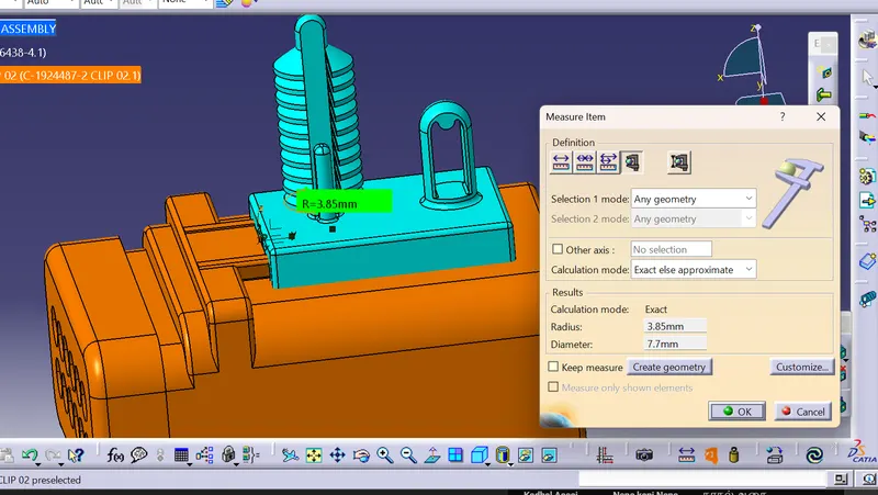
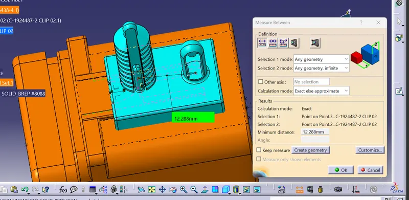
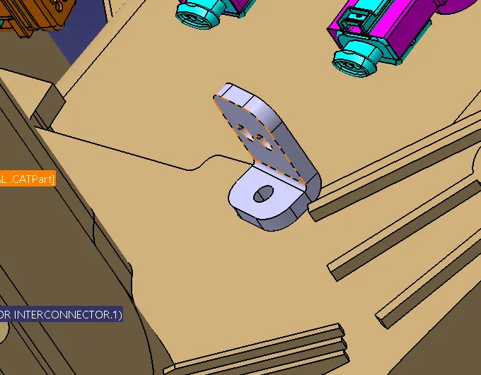
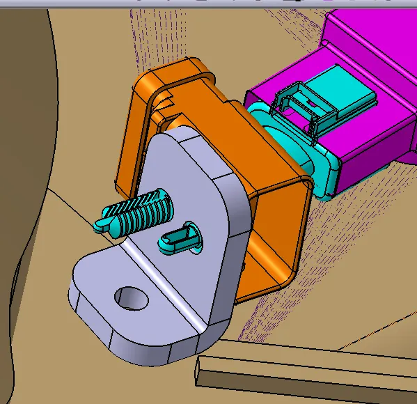
So the inter conner is properly aligned at the desired specified location
Align the guiding channel at the desired specified location
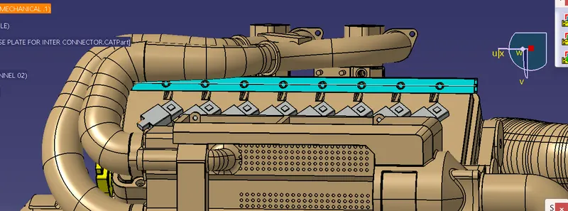
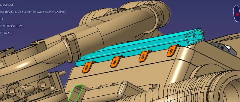
Now align the specified connectors at their specified location
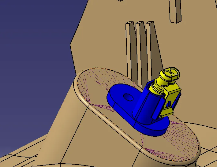
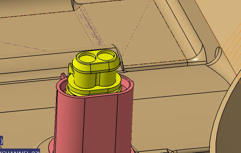
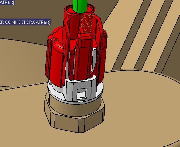
Arrange the p clamps and the firr tree clips at the right loaction for the proper bundle formation so that the bundle routing attained is logical
The general placement of the components can be attained by using the compass or the manipulation tool or the snap mode method
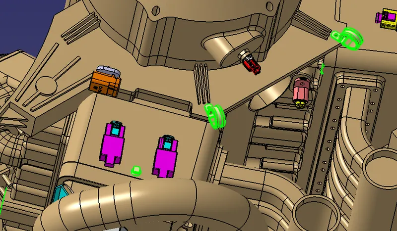
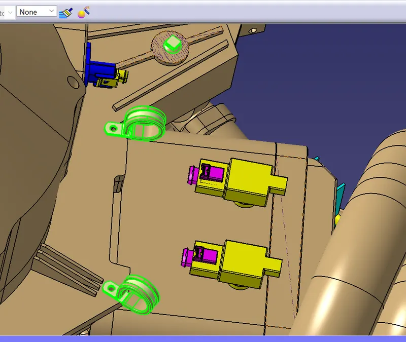
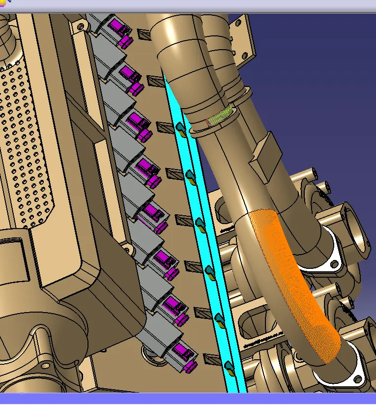 .
.
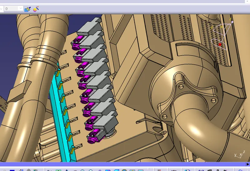
Now all the electrical components are set at the desired specified logical location for the proper bundle routing process
Now go to the electrical harness wotrkbench for the bundle routing initiation
Once we go to the electrical harness workbench activate the geometrical bundle and define itb as the electrical so the product file image of the geometrical bundle changes to the electrical product file


Now go to the multi branching command and start routing the bundles between the connectors by foollowing the desig rules and considerations
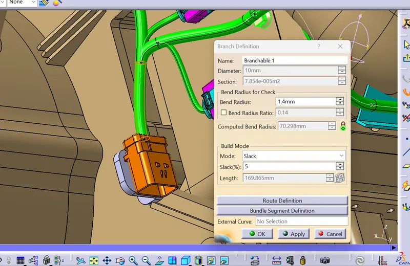
Provie the diameter of the bundle segment and make sure the bend radius is sety default at 1.4 mm for all the bundle segments and then provide some amount of slack for the proper logical formation of the bundle segment to avoid the tension among the bundles which leads to the breakage of the bundles then define the route defnition between any two bundle segment points to form the bundle
Now continue to route the bundle for all electrically defined components

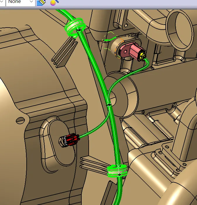
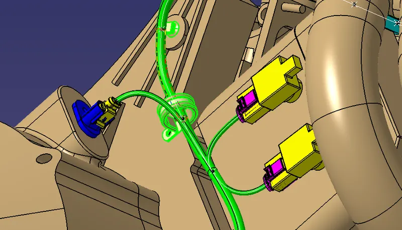
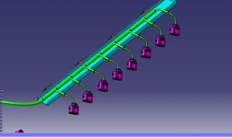
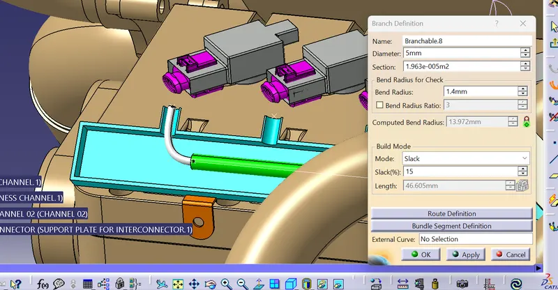
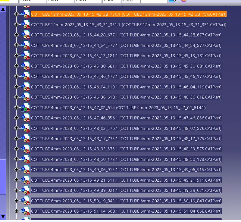
Nowe apply the cottubes required on the bundle sto provide the protection from damage , water resistance , dust resistance
The bundles under the guiding channel doesnt need to provide with any protection devices as it will be closed and sealed properly
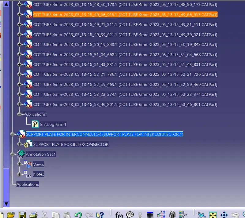
Cot tubes of 12 mm, 6 mm, 4 mm are usesd
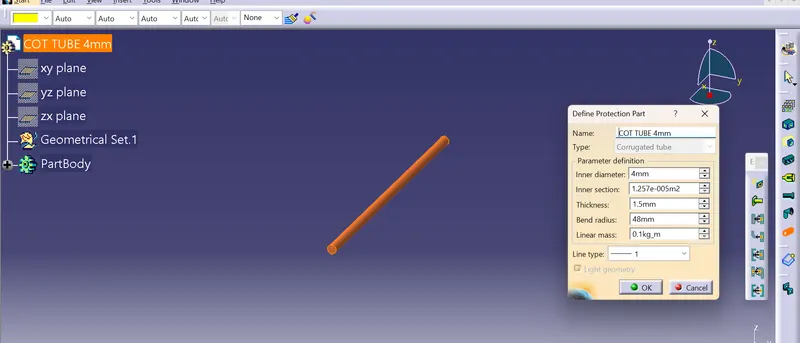
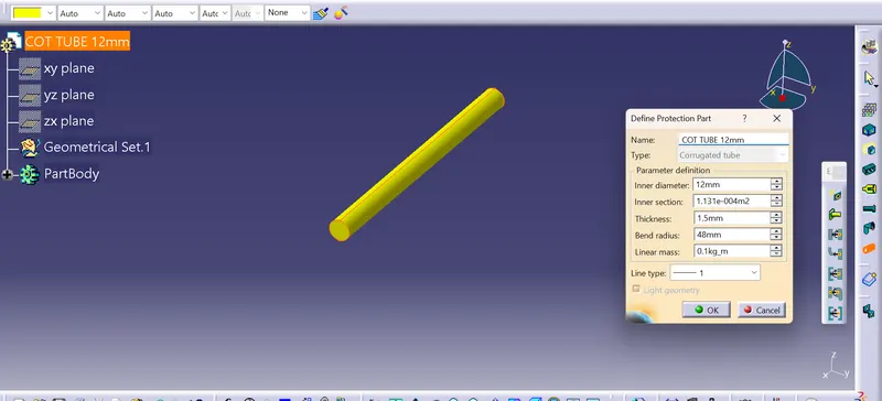
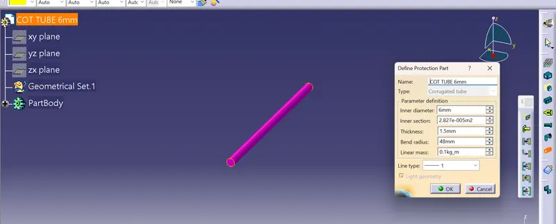
Store all the cot tubes in the catalogue for opting in the assembly
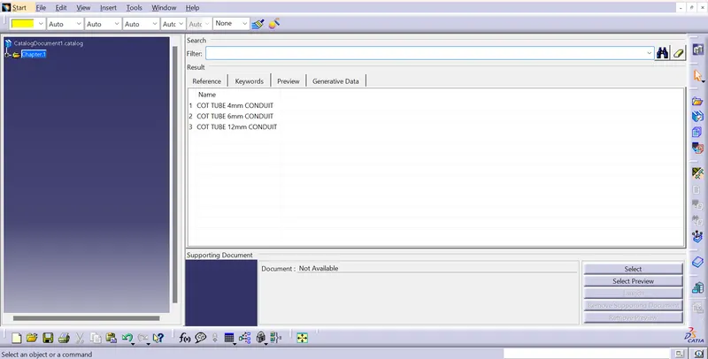
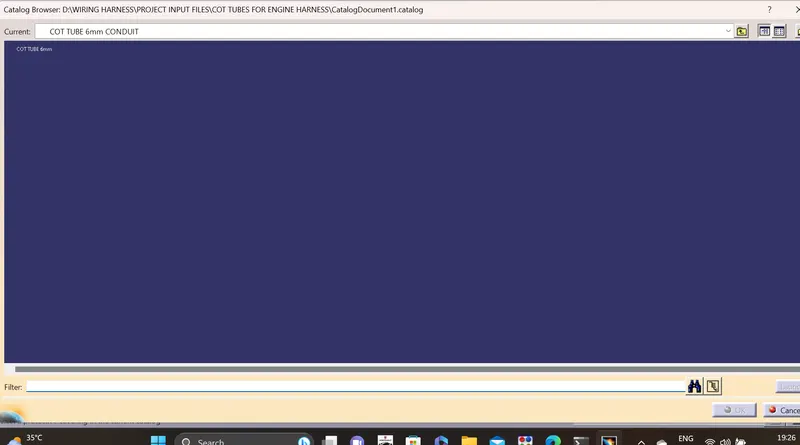
Now opt the cot tubes from the catalogue and select the bundle for applying the cot tube and adjust the start point and the end continuity
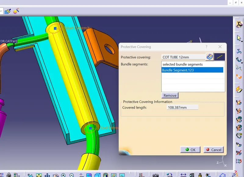
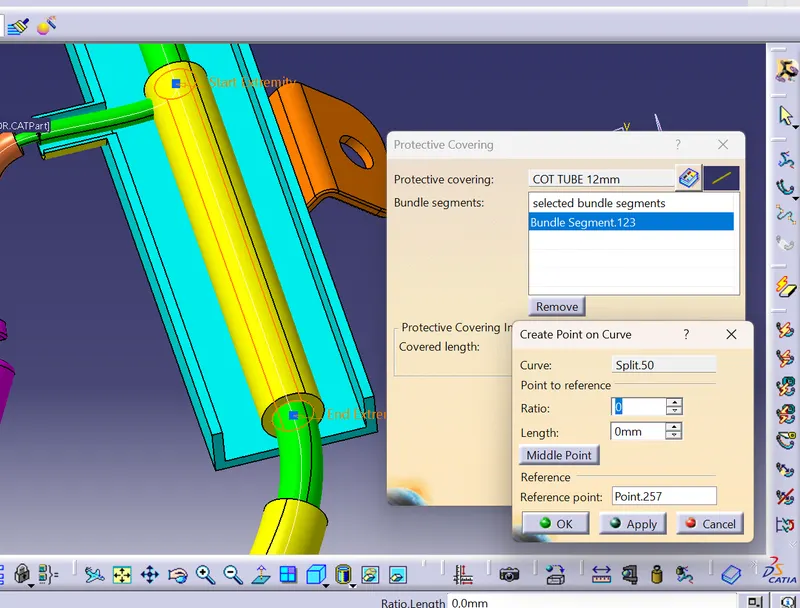
Now apply for all the bundles
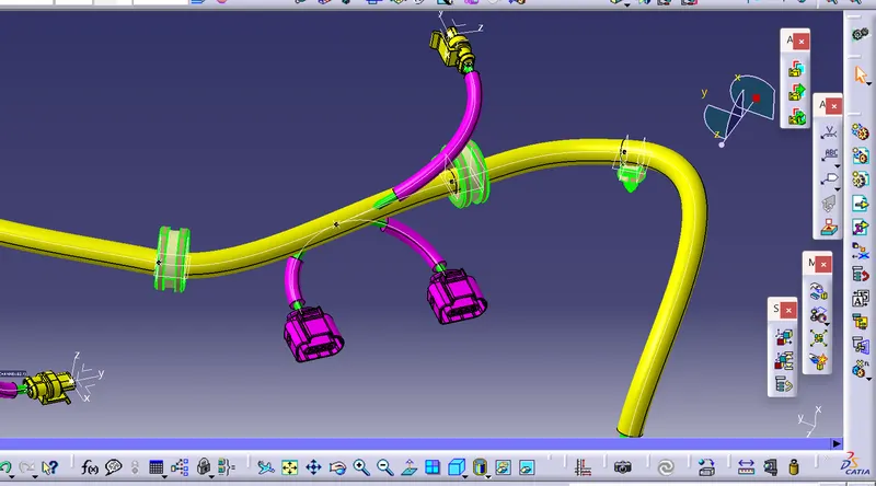
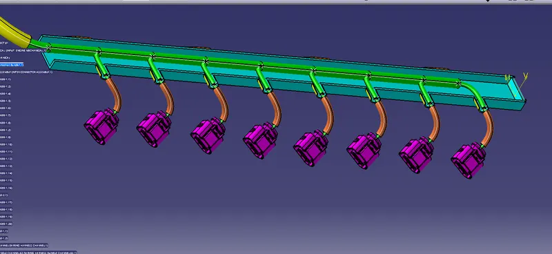
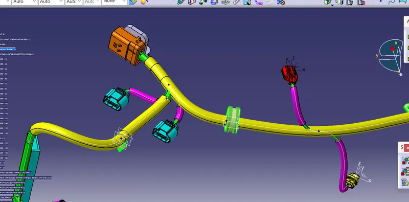
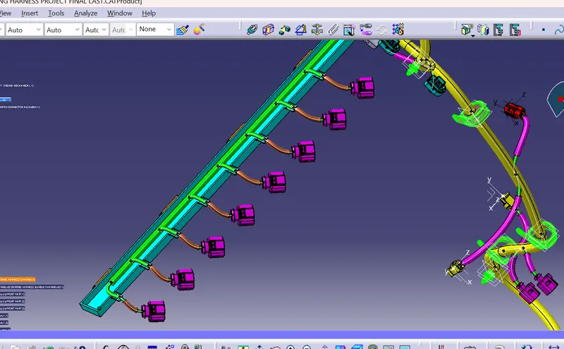
Once all the bundles are routed completely we need to check the bundle continuity that means whether all the bundles are connected properly
For this go to edit < search < Electrical worbench < bundle segment < Fully connected < False
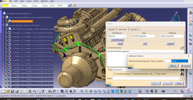
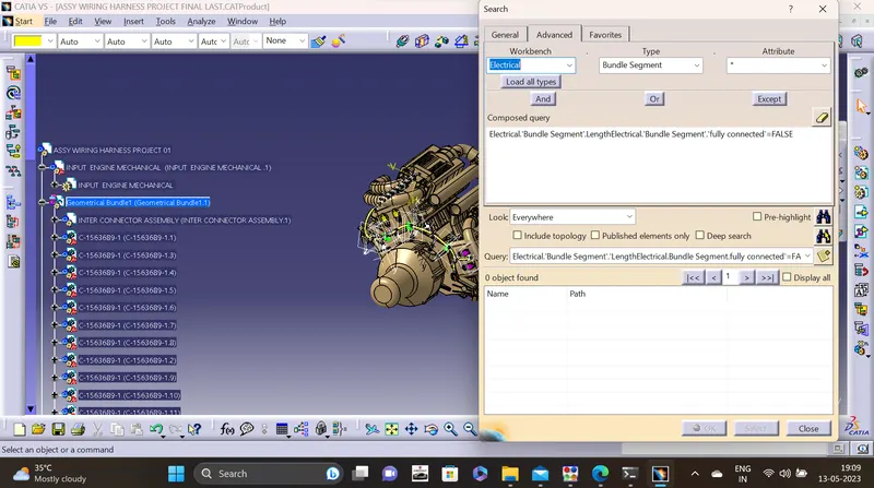
It shows no discontinuity between the bundles that means all my bundles are fully connected with each other
Now save the file as the save management option then save < propgate directory then all the product files of the wiring harness assembly stored at one place
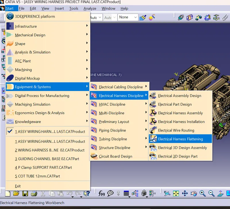
Now continue with the flattening of the wiring harness assembly for this go to start < equipments & sytems < Electrical harness discipline < electrical harness flattening
Provide the harness parameters
They are basically
setting 01:
They are basically
Setting 01:
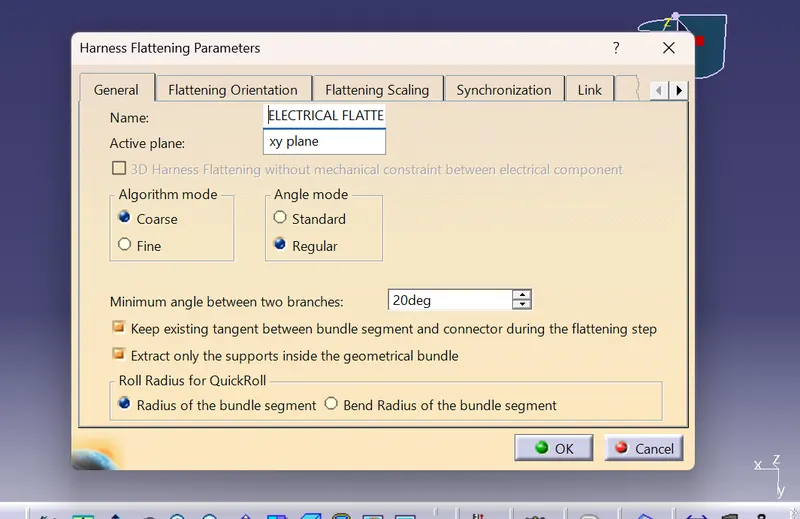
- we need to provide the name for the flattenings and the active plane that the flattening should be done
- the minimum angle should be kept at approx 20 Degrees
- The tangent (vector position )for the bundles should be adopt from the geometrical bundle of the wiring harness assembly cat product file
- We need to check the Extract the supports only from the geometrical bundle so that no background data is allowed for flattening in the workbench
- Roll radius of the qickball or for the roll feature is obtained from the radius of the bundle segment
Setting 02:
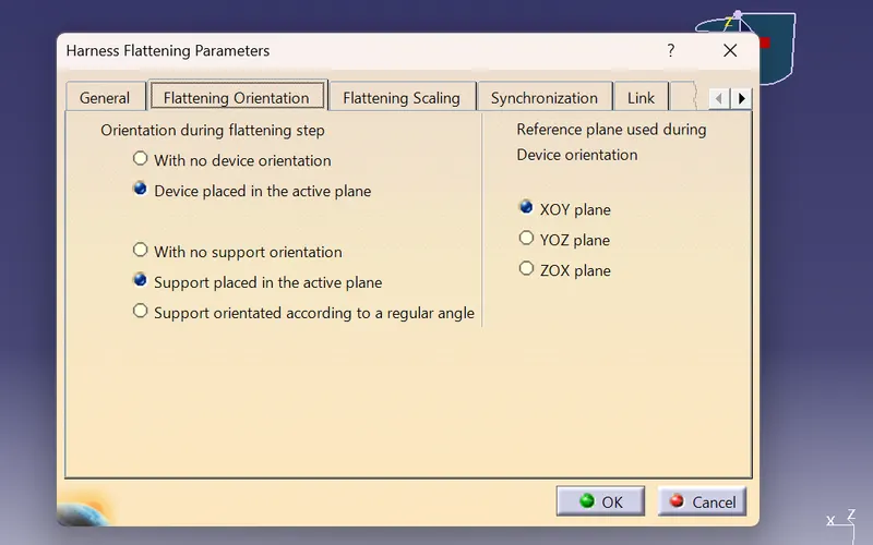
These are the parameters which are adjusted by the catia automatically so continue without making any considerable changes in the flettening orientation settings
Setting 03:
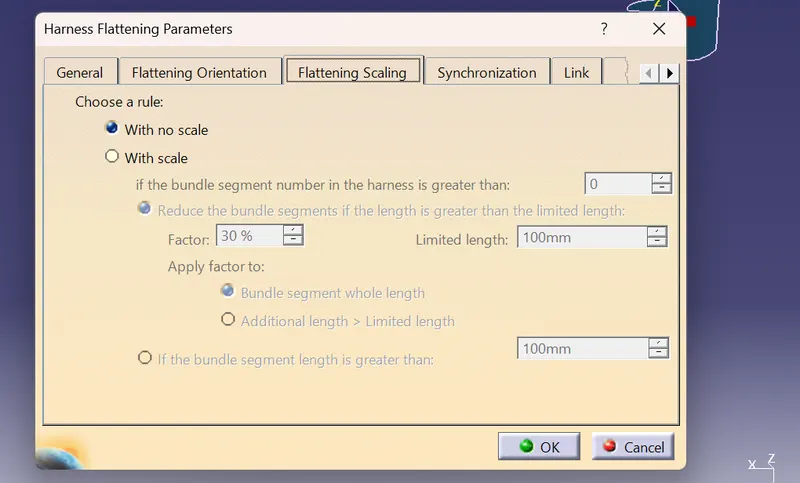
The flattening scaling is very useful as it would like to fake the dimension of the product in the flattening workbench as adjusted as the wiring harness product components are very long so just dont alter anything any continue
Setting 04:
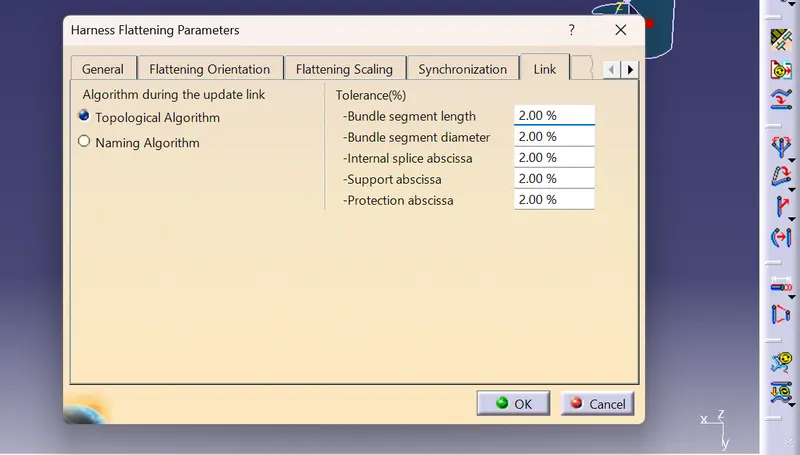
These are the parameters which are adjusted by the catia automatically so continue without making any considerable changes in the link settings
Setting 05:
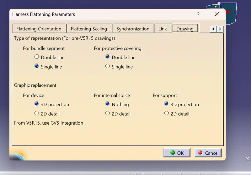
The bundle segment representation either in single line / double line
For rotective covering single line / double line
This the setting which will help us to get the better output in the drawing sheet adopted from the flattening
Aim : To create the wiring harness flattening sheet for the challenge 4 cat product
First we need to craete anew product and apply the flattening settings required and store in a desired location
Now open the challenge 04 cat product and save this product to the same desired location where the flattening cat product is saved so that when any changes are ,ade in the challenge 04 cat product those changes can be easily adopted to the flattening product by using the synchronize feature in the flattening workbench 
Now open the two products vertically side by side and click on the flattening product < Extract command < geometrical bundle
Use the flatten command and select the face and select one bundle segment asnd click on select all branches and apply ok.
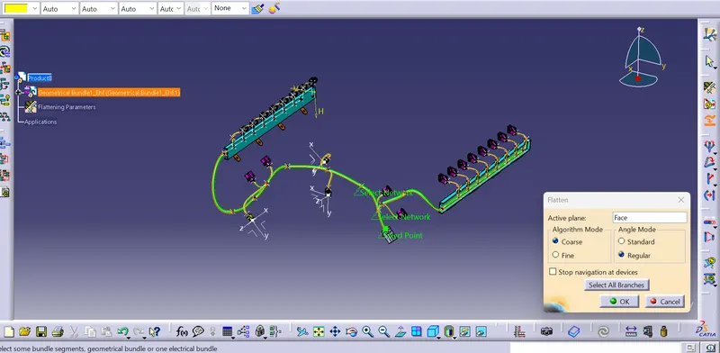
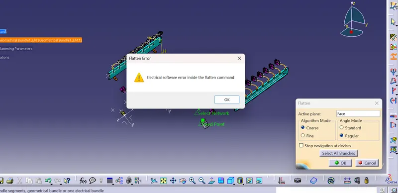
Now it shows there is a software licence issue so i mentioned the problem to one of the mentor and he sent me a file for flattening then i proceed the provided file for the flattening drawing
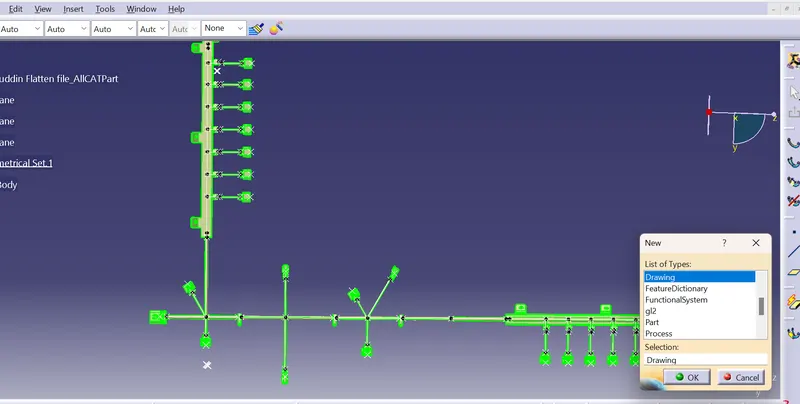
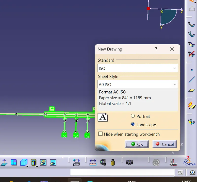
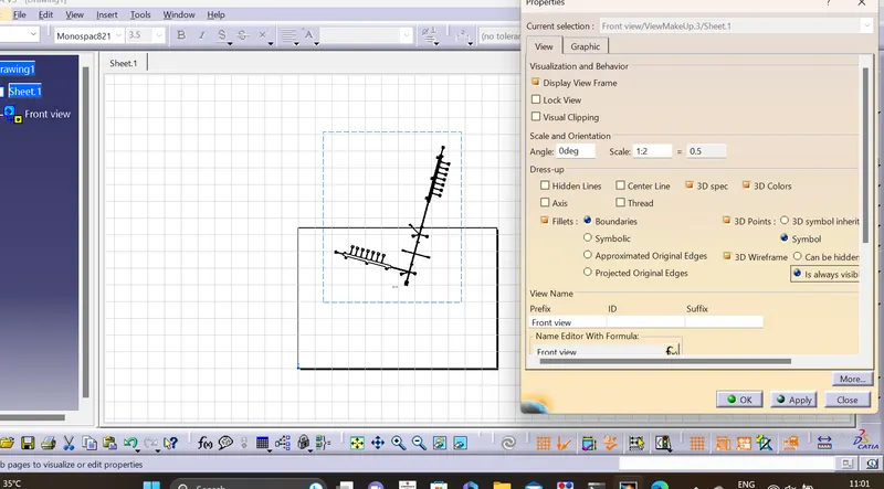
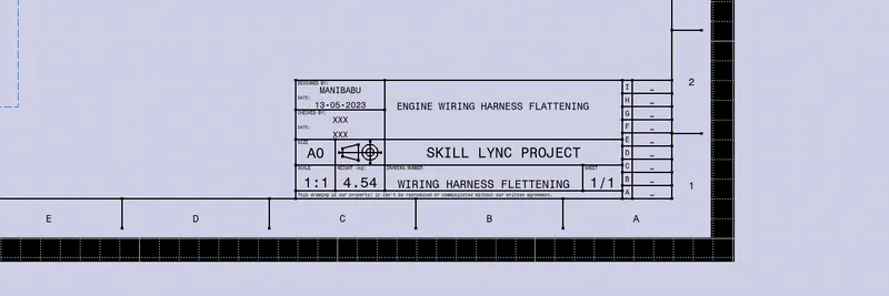
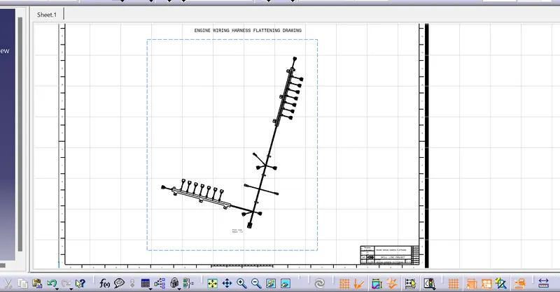
Mark the title and the frame block for proper represenration
Conclusion: Finally the wiring harness for the engine is completed and proper routing of the bundles are arranged by following certain design rules and considerations and checking the bundle continuity along side followed wuith the flattening of the wiring harness anf drawing for the flattening product
Tree structure