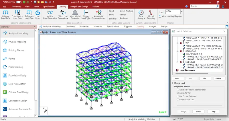
Project 1
A residential society has 200 x 2BHK flats and 100 x 3BHK flats. A typical family in a 2BHK flat has 3 persons/flat and a 3BHK flat has 4 persons/flat. The gross water demand (per person per day in liters) can be calculated by taking the aggregate of the usage for all the below listed activities.
|
Activities |
Consumption (per person/day in litres) |
|
Drinking |
5 |
|
Cooking |
45 |
|
Bathing |
30 |
|
Toilet Flushing |
25 |
|
Cloth Washing |
35 |
|
Miscellaneous use |
10 |
As per given data total persons in the residential society is 1000.
Per day one person water usage is 150litres.
Total water consumbtion per day in residential society is 150000litres.
Constraints & Site Data:
- One of the dimensions of the underground water tank is limited by the width of the internal road in the residential society as this is the ideal location of an underground water tank in case of a fire emergency. The width of the road could be taken as 6 meters and thus the width dimension of the tank cannot exceed 6 meters.
- The bearing capacity of the soil at different founding depths is given in the table belo
|
Founding Depth (Below F.G.L) |
S.B.C (Tonnes/sqm) |
|
-3.00 m LVL |
7.5 |
|
-4.00 m LVL |
8 |
|
-5.00 M LVL |
8.5 |
Consider an allowable soil settlement of 25 mm under the base slab.
- The top cover slab thickness is 500mm for a maximum one-way direction span of 4 meters. Use a structural beam of dimensions 500 x 900 (min concrete grade M25) if the span of the top slab exceeds 4 meters in order to break the span. Note that the beam and the top slab doesn’t need to be designed under current problem statement.
Loadings:
- For the top cover slab, the maximum live load to be assumed is 15 kN/m2 and a maximum superimposed dead load is 3 kN/m2.
- Consider unit weight of soil 18 kN/m3 and unit weight of water 10 kNm3. The soil needs to be considered in a saturated state.
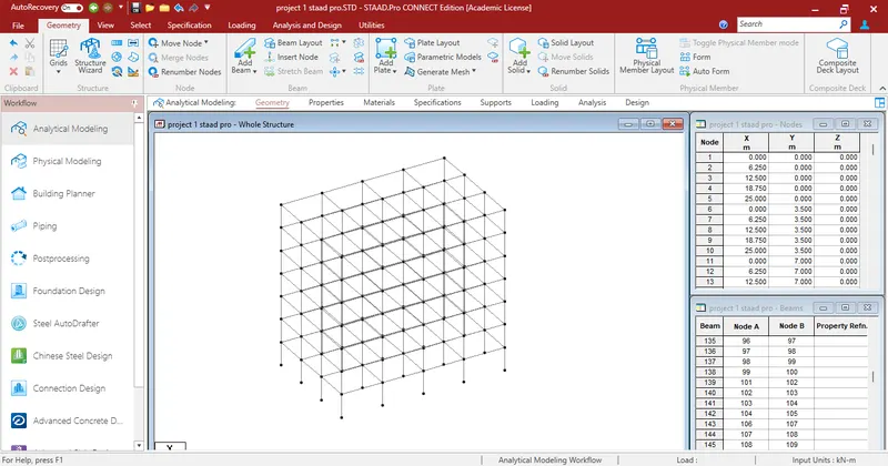
Create a full-scaled 3D STAAD pro model of the underground water tank complying with the calculated demand, site constraints and the best practice guidelines for FEA. The final model should consist of all the applicable loadings on the structure, support conditions, material specifications and an average mesh size of 500 mm. The modelling of the entire geometry shall be based on center line approach and the model should be devoid of any errors or warnings.
Materials unit weight as per the code
Safe Bearing Capacity = 18kN/m^3
Plain cement concrete = 24kN/m^3
Reinforced cement concrete = 25kN/m^3
Cement concrete screed = 20kN/m^3
Cement masonry = 22kN/m63
Structural steel = 78.5kN/m^3
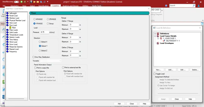
Loads of a building
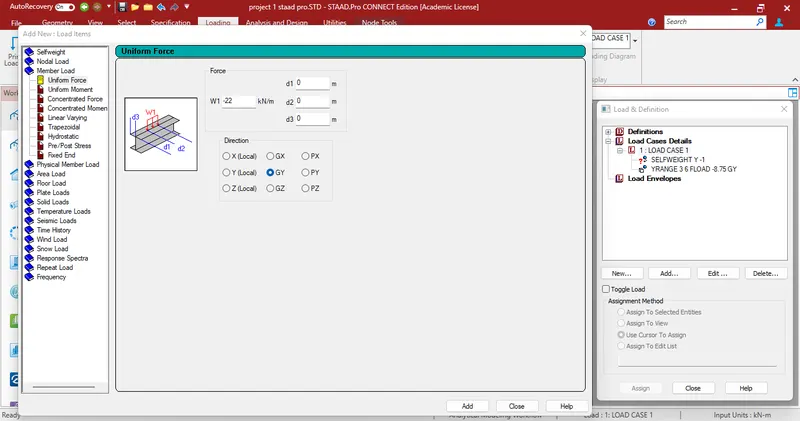
Slab weight = 3.75kN/m^2(0.15mx25kN/m^3)
Partitions = 1.5kN/m^2
Floor finish = 2.5kN/m^2
, Others = 1kN/m^2
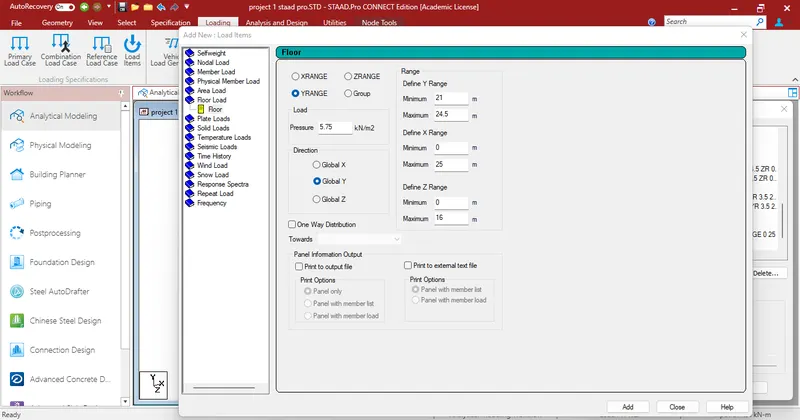
Total floor load = 8.75kN/m^2
Slab unit weights
Slab weight = 3.75kN/m^2(0.15mx25kN/m^3)
Insulations and water proofing = 0.5kN/m^2
MEP services = 0.5kN/m^2
Others = 0.5kN/m^2
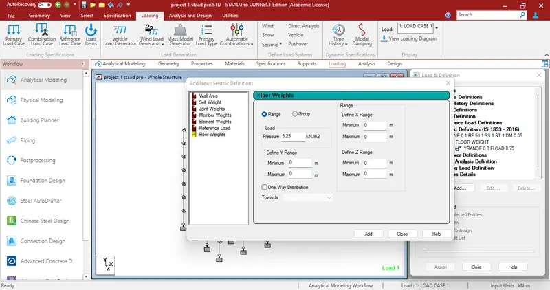
Total roof load = 5.25kN/m^2
Common corridor = 3kN/m^2
Total floor load =3kN/m^2
Accessible roof = 1.5kN/m^2
Total roof load = 1.5kN/m^2
Design of slab(IS-456)
Span shorter direction(clear) Ly = 3.125m
Span longer direction(clear) Lx = 5.5m
Live load on the slab(LL) = 3kN/m
Compressive strength of concrete(Fck) = 25N/mm^2
Yield strength of steel(Fy) = 415N/mm^2
Unit weight of concrete(Yc) = 25kN/m^3
Unit weight of floor finish 100mm(Y) = 22kN/m^3
Clear concrete cover = 25mm
Bearing slab(B) =250mm
Step - 1
Span to effective depth ratio L/d = 32
Minimum effective depth(d) = 97.67mm
Overall depth(D) = 127.66mm
Dia of bars in shorter direction = 10mm
Dia of bars in longer direction = 10mm
Effective depth(d) = 120mm
Loading on the slab
Dead load of the slab(DL) = 3.75kN/m^2
Super dead load = 5kN/m^2
Live load on the slab = 3kN/m^2
Total load on the slan = 11.75kN/m^2
Design load = Total load x load factor
= 17.63kN/m^2
Effective span Lx = 3.25m
Ly = 5.62m
Lx/Ly = 1.732 (two way)
| 1.5 | Alpha x | 1.75 | Alpha y | |
| For negative moments (at top) | 0.075 | 0.104683 | 0.107 | 0.084 |
| For positive moments (at bottom) | 0.056 | 0.103307 | 0.107 | 0.063 |
Step - 2
BM per unit width of slab
| Mx=αxwLx^2 | My=αywLy^2 | |
| For negative moments (at top) | 19.43 | 15.59kN-m/m |
| For positive moments (at bottom) | 19.17 | 11.69kN-m/m |
Shear force V = 0.5WLx =28.6 kN/m
Step - 3
To check the effective depth of slab
Mu,lim = 0.138Fckbd^2
d = 74.55mm
Step - 4
Depth of slab for shear force
Tc,max = 3.1N/mm^2
Tc = 0.3
K = 1.2
D = 200mm
Tc = 0.3N/mm^2
Tv = Vu/bd
= 0.24N/mm^2
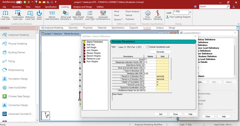
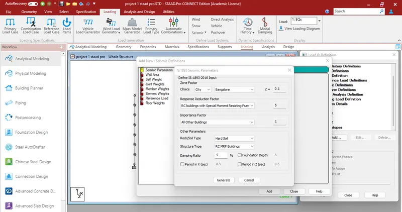
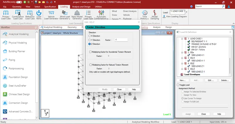
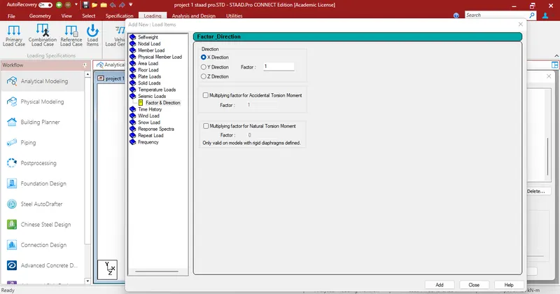
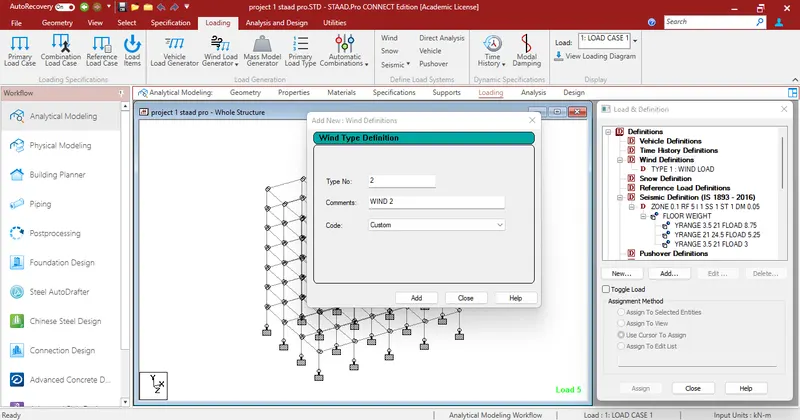
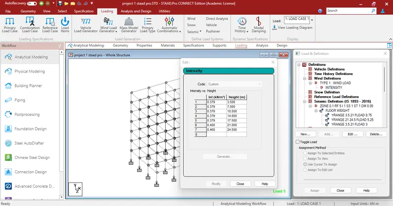
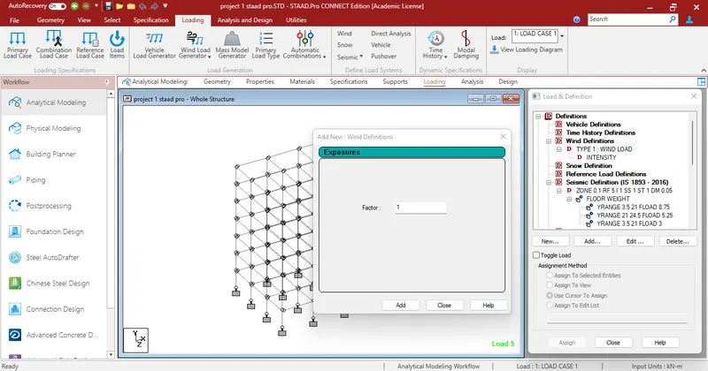
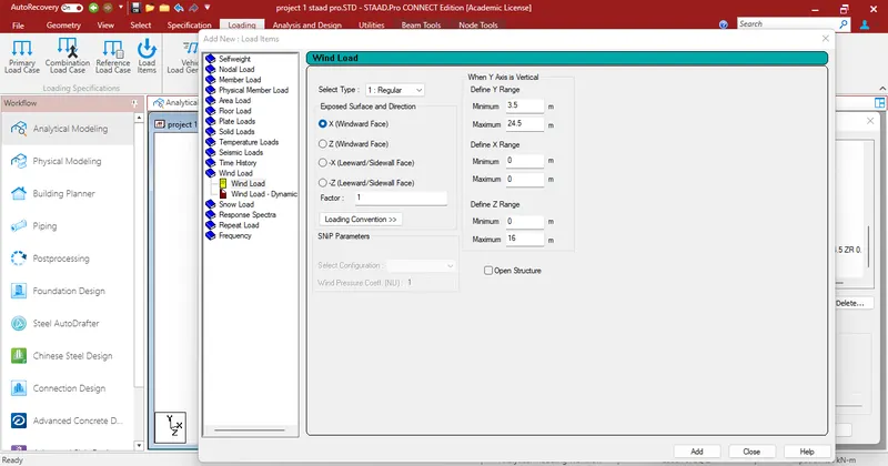
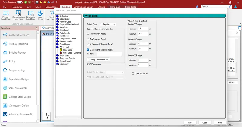
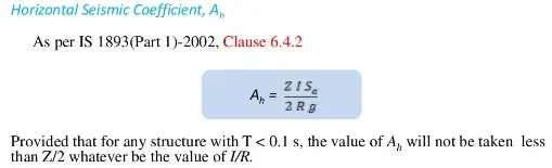
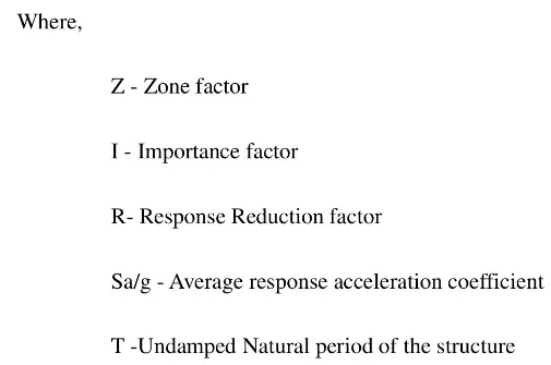
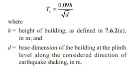
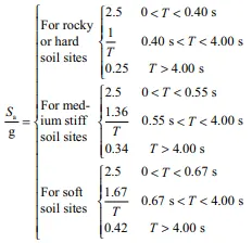
Tv 0.24<0.36<3.1 SAFE Step - 5 Determination of area of steel Mu = 0.87FyAstd(1-AstFy/Fckbd) For negative moment Mutop = 19.43kN/m Ast = 561.65mm^2/m For positive moment Mubottom = 19.17kN/m Ast = 554.27mm^2/m Determination of distribution steel Astmin = 0.12bd = 114mm^2 Selection of steel reinforcing bars Area of bars(Top steel) = 78.5mm^2 Spacing = 140mm = 125mm provide 16mm bqars at a spacing 125mm Area of bars(Bottom steel) = 78.5mm^2 Spacing = 142mm =125mm Provide 16mm bars at a spacing 125mm Calculation of wind load (IS875-Part 3) Design wind speed Vz = Vbk1k2k3k4 m/s Basic wind speed(Bengalore) Vb = 33m/s Probability factor k1 = 1 Terrain factor k2 = Category 4B Topography factor k3 = 1 Design wind pressure Pz = 0.6Vz^2 Calculation of Seismic Load (IS1893-Part I) Design base shear VB = Ah x W Where, Ah = horizontal seismic coefficient as calculated as per 6.4.2 W = Total weight of the structure Zone factor Z = 0.1 (Bngalore) Soil condition factor Sa/g Height of building h = 24.5m Base dimension of building Along-X = 25m Along-Z = 16m T along-X = 0.5513sec T along-Z = 0.4410sec Sa/g for hard soil = 1/T = 1.814 Along X = 2.268 Along Z Responce reduction factor R = 3 Importance factor I = 1.2 Horizontal accelaration co-efficient Ah = 0.0363 = 3.6812% Seismic weight Area of each floor A = 400m2 Due to dead loads Typical floor DL = 12.5kN/m2 W DL = 5000kN Due to dead loads, roof DL roof = 9kN/m2 W DL roof = 3600kN Due to live loads, Typical floor LL = 3kN/m2 W LL = 300kN/m2 Due to live loads, Roof LL = 1.5kN/m2 W LL roof = 0 Total seismic weight W = 35400kN Design base shear VB = AhxW = 1605.44kN
Floor
Height
k2
Vz
Pz
Pz in kN
1
3.5
0.76
25
377.40
0.38
2
7
0.76
25
377.40
0.38
3
10.5
0.76
25
377.40
0.38
4
14
0.76
25
377.40
0.38
5
17.5
0.76
25
377.40
0.38
6
21
0.76
26
397.53
0.40
R
24.5
0.76
26
461.04
0.46
 ,
,