Project 1
Q.1 answer
Objective:
Route the Wiring harness on the Given Engine and Prepare to flatten the view drawing in CATIA V5. Application of all Packaging rules, Industry best practices studied in this course shall be demonstrated in design. Apply Protection coverings as required.
Prepare & Submit all necessary reports like clearance, Clipping/Clamping selection, Harness fixing requirements, Harness continuity, and Assumptions if any along with CATIA 3D data.
WIRING HARNESS FOR ENGINE
AIM:
- To route the wiring harness for the given engine.
- Application of all Packaging rules, Industry best practices studied in this course shall be demonstrated in design.
- Apply Protection coverings as required.
INTRODUCTION:
WIRING HARNESS OR CABLE HARNESS:
A cable harness, also known as a wire harness, wiring harness, cable assembly, wiring assembly, or wiring loom, is an assembly of electrical cables or wires which transmit signals or electrical power. The cables are bound together by a durable material such as rubber, vinyl, electrical tape, conduit, a weave of extruded string, or a combination thereof.
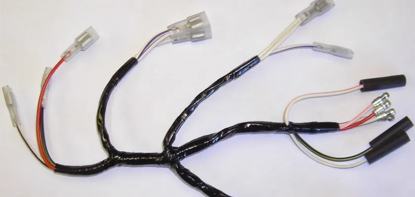
1. Wiring Harness
Cable harnesses are usually designed according to geometric and electrical requirements. A diagram is then provided (either on paper or on a monitor) for the assembly preparation and assembly.
The wires are first cut to the desired length, usually using a special wire-cutting machine. The wires may also be printed on by a special machine during the cutting process or on a separate machine. After this, the ends of the wires are stripped to expose the metal (or core) of the wires, which are fitted with any required terminals or connector housings. The cables are assembled and clamped together on a special workbench, or onto a pinboard (assembly board), according to design specifications, to form the cable harness. After fitting any protective sleeves, conduit, or extruded yarn, the harness is either fitted directly in the vehicle or shipped.
PACKAGING RULES:
- Wiring harness routing shall provide ease in manufacturing, accessibility, easy removal, and easy maintenance of attached equipment and wiring harnesses.
- Routing through small structural holes and openings shall be avoided, minimizing chaffing and handling of the wiring harness during installation.
- Avoid the harness routing and clipping in the Blind zone of the Operator during harness assembly or in service.
- Routing shall offer protection against possible damage through common misuses such as being handheld and temporary support for test equipment.
- Provide additional slack to the harness according to the surroundings and harness bending requirements.
- Ensure the routing meets the clearance requirements with different surrounding parts.
- Avoid routing over the bolts, near the bolted joints. It may damage the harness or puncture the harness. Keep harnesses away from panel mounting screws.
- Avoid harness routing near sharp edges, if not possible provide protection to the harness.
- The maximum distance between two clips on a straight branch is 200mm.
- Provide Clips and clamps if the harness is going to bend at multiple locations.
- The use of too many sheet-metal brackets should be avoided.
- The branch length should be more than 50 mm.
- Min distance between the clip and the branching point is to be 25 mm.
- Min distance between two branch breakouts should be 50 mm.
Assumptions-
- Provide clips/clamps as per requirement.
- Make sure that there is no falling case while designing the wire harness. Additional clips/clamps may be used to avoid falling cases.
- Give additional slack if needed. 5-10% slack is sufficient.
- Avoid routing over the bolt and bolted joints to avoid harness puncture.
- Avoid routing on sharp edges or else provide protection over the harness.
- Follow the clearance distance and keep away the harness from heat generation components.
- Protection should be provided as needed according to the surrounding temperature.
- Avoid direct support for harnesses on fuel lines routed in the engine.
- Use plastic guiding channels if needed.
- The branch length should be greater than 50mm.
- The minimum distance between two branch points should be at least 50mm.
- The minimum distance between the clip and the branch point should be at least 25mm.
- Avoid too many sheet metal brackets on the engine. Try to use available threaded bosses on the engine or demand for it.
- The wiring harness should be easy to assemble and easy to access.
- While using dummy connectors, ensure that whatever positions you are defining is practical. Bundle diameters and other placements can be defined properly for the wire harness routing.
- If the packaging area is too tight and there are many packaging constraints then we can think of creating a harness channel that can be used to route and protect the wire harness effectively
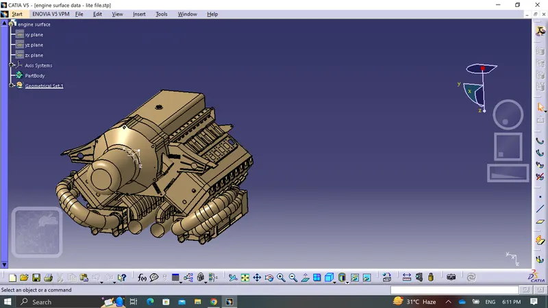
The objective of the project is to route the wiring harness on given Bugatti V16 Engine and prepare flatten view drawing in CATIA V5. All types of packaging rules have to be considered while routing the harness. Also, Industry best practices should be demonstrated in design. All the necessary details like clearance, clipping/clamping selection, harness fixing requirements, harness continuity should be provided in order to design wiring harness.
- The above figure shows the 16 valve Bugatti Engine where 8 cylinders are placed on the right side and 8 cylinders are placed on the left side.
- There are total 16 injectors where 8 injectors are used for 8 cylinders on right side and 8 injectors are used for another 8 cylinders on left side.
- Also there are 4 cam-shaft sensors, so there are total 20 sensors that we have to connected electrically.
- Generally, 4-pole connectors are used for fuel injectors of the engine.
- The engine will also have an interconnection connector which will connect the engine to other parts of the vehicle. We will be using a 12-pole electrical connector with a mounting clip feature as an interconnection connector.
- The plastic guiding channel used in this harness should bemade of a material that can withstand at least 150 degree Celcius.
- The bend ratio for the all bundle segmets should be 1.4
- 16 valve Bugatti Engine.
Assumptions-
Step 1: Creating Context Assembly
- A Context Assembly for Engine Harness has created which will work as the main assembly as shown in above figure.
- A Context Assembly will contain Engine Assembly data for Bugatti V16 Engine and Engine Harness Geometrical Bundle Assembly.
- If any sheet metal bracket will require then they are added in the context assembly.
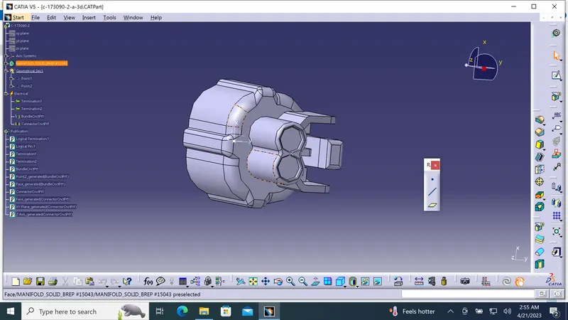
Step 2: To define 4-pole connector electrically
We have to define all the connector that is 2 pole, 3pole, 4 pole and 12 pole interconnection connector as an electrical part by define as connector connection point and bundle connection point.
Also define the clip and channels that is needed as an electrical part.
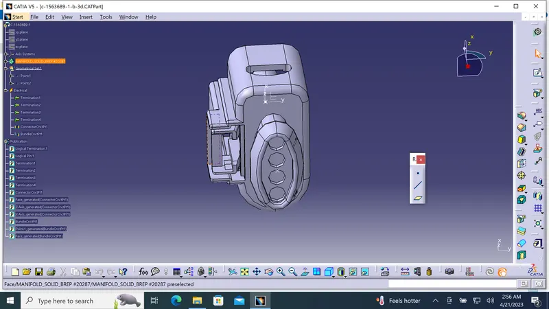
Step 3: Adding connectors to the all 16 fuel injector sensors and 4 cam-shaft sensors
In this step, we are placing connectors to fuel injector sensors and cam-shaft sensors. So we will require total 20 connectors which have to be added in the Engine Harness Geometrical Bundle Assembly. We have to use manipulation tools along with compass, snap and smart move features to locate all the 20 connectors at their desired locations.
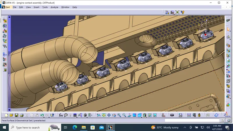
Step 4: Adding sheet metal bracket
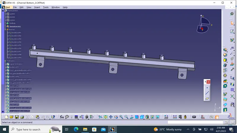
Step 5: Mounting the interconnection connector on the sheet metal bracket and mounting the p-clamps for wire harness
Step 6: Mounting of a plastic guiding channel
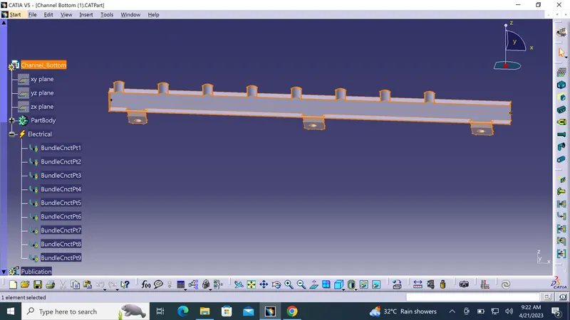
Step 7: Bundle routing from Interconnection connector to 3 P-clamps
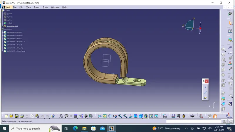
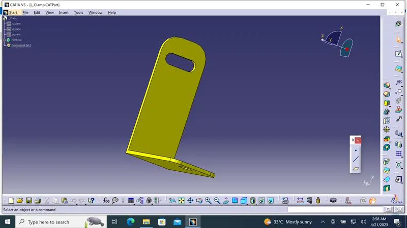
Step 7: Bundle routing from Interconnection connector to 3 P-clamps
Step 9: Routing to the plastic guiding channel
Step 10: Adding branch points to bundle segment inside the guiding channel
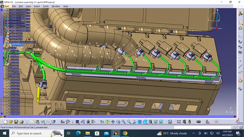
Step 11: Adding protective coverings and guiding channels top shell to harness bundle
Step 12: Checking bundle continuity
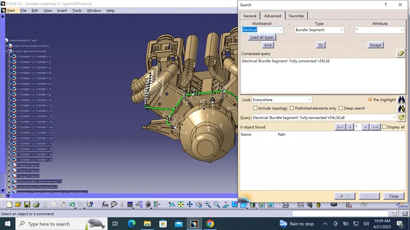
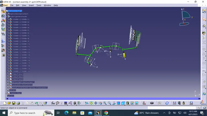
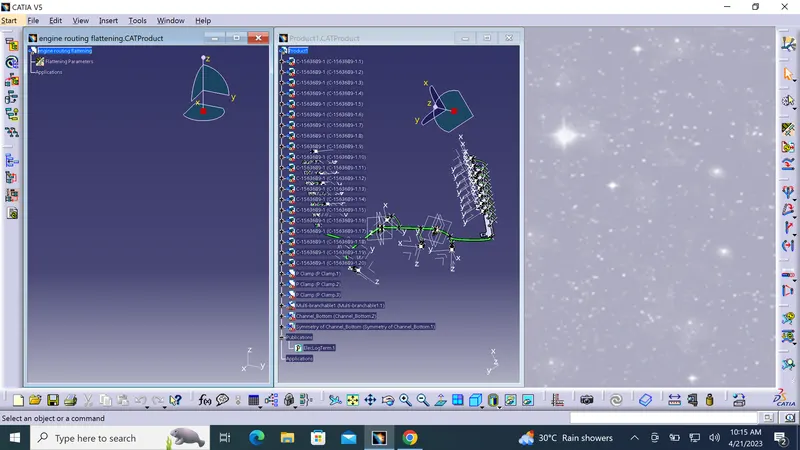
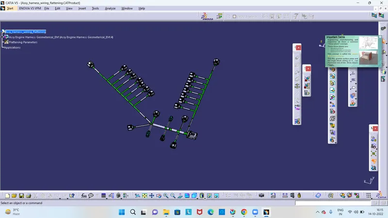
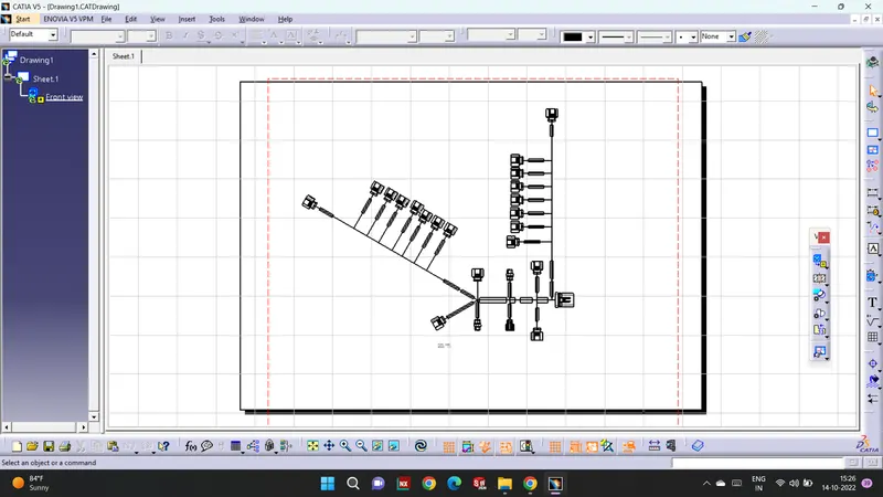
NOTE-Due to some software issue i was doing it with TSE Mr.MAHENDRANATH but due to some software issue i was not able to get proper flattening .So i have attached result also pfa.