Designing of battery pack for a car roughly 150 Kw with 120 V, Using 3500 mAh 3.6V nominal NMC chemistry cell.
1.Design a battery pack for a car roughly 150 Kw with 120 V. Use 3500 mAh 3.6V nominal NMC chemistry cell.
a. Design the battery pack configuration.
b. Draw the BMS topology for this battery pack.
ANSWER:
Aim of the Project:
The aim of this project is to design a battery pack for a car with the given specifications, using NMC chemistry cells. The battery pack needs to be safe, reliable, and efficient, with a high energy density and power output. The project also involves designing a BMS to monitor and control the battery pack, ensuring safe and efficient operation and build matlab /simulink model for 3s2p pack configuration.
Design a battery pack for a car roughly 150 Kw with 120 V. Use 3500 mAh 3.6V nominal NMC chemistry cell:
To design a battery pack for a car with a power rating of 150 kW and a voltage of 120V, we can use 3500 mAh 3.6V nominal NMC chemistry cells.
The first step is to determine the battery pack configuration, which involves deciding the number of cells in series and parallel connections. In this case, we calculated that 34 cells should be connected in series to achieve a rated voltage of 120V, and 358 cells should be connected in parallel to handle the continuous current of 1250 A.
The NMC chemistry cells are commonly used in electric vehicles due to their high energy density, low cost, and long cycle life. This battery pack configuration is designed to provide sufficient power to drive an electric car with a power rating of 150 kW, which is equivalent to 201 horsepower.
Overall, designing a battery pack for an electric car involves careful consideration of various factors such as power requirements, voltage ratings, and chemistry types to ensure optimal performance and efficiency.
a. Design the battery pack configuration.
To design the battery pack configuration, we need to determine the number of cells in series and the number of cells in parallel.
Given parameters:
- Battery pack configuration power = 150 kW
- Rated voltage of the battery = 120 V
- Battery capacity = 3500 mAh
- Nominal voltage = 3.6V
To calculate the number of cells in series:
Nominal voltage per cell is 3.6V, and the rated voltage of the battery is 120V. Therefore,
Number of cells connected in series = Battery rated voltage / Nominal voltage per cell = 120V / 3.6V = 33.33 cells
Rounding off the calculated number, we get 34 cells connected in series.
To calculate the number of cells in parallel:
The continuous current is not given, so we need to calculate it first.
Power (P) = Voltage (V) * Current (I)
Therefore, Current (I) = Power (P) / Voltage (V)
Substituting the given values, we get:
Current (I) = 150 kW / 120 V = 1250 A
The nominal capacity per cell is 3500 mAh or 3.5 Ah.
Number of cells in parallel = Continuous current / Nominal capacity per cell = 1250 A / 3.5 Ah = 357.142 cells
Rounding off the calculated number, we get 358 cells connected in parallel.
The number of cells in serise is = 34 cells.
The number of cells in parallel is = 358 cells.
Hence, the battery pack configuration is 34 cells connected in series and 358 cells connected in parallel, with a total of 12212 cells in the battery pack.
b. Draw the BMS topology for this battery pack.
Battery management systems (BMS) play a critical role in ensuring the safe and optimal operation of electric vehicle (EV) batteries. The BMS is responsible for monitoring the battery's state of charge (SOC), state of health (SOH), and state of function (SOF) and protecting it from potentially damaging conditions such as overcharging, over-discharging, and over-temperature. In this context, selecting the appropriate BMS topology for a particular EV battery is crucial.
There are various types of BMS topologies available in the market, including centralized, distributed, modular, and integrated. Each topology has its unique advantages and limitations, which we will discuss in detail below.
-
Centralized BMS: In a centralized BMS topology, a single control unit monitors all the cells in the battery pack. The control unit is connected to each cell via individual wires or a bus. The centralized BMS architecture is relatively simple and cost-effective, making it a popular choice in the industry. However, it suffers from several drawbacks, such as increased wiring complexity, limited fault tolerance, and lower reliability, making it less suitable for high-voltage battery packs.
-
Distributed BMS: In a distributed BMS topology, each cell in the battery pack has its own monitoring circuit. These monitoring circuits are connected to a central control unit, which aggregates the data and provides the necessary control signals to each cell. The distributed BMS architecture has several advantages over the centralized topology, such as higher reliability, better fault tolerance, and lower wiring complexity. However, it is more complex and expensive to implement, making it less attractive for low-cost applications.
-
Modular BMS: In a modular BMS topology, the battery pack is divided into smaller modules, each with its own BMS. The modules are connected in series or parallel to form the final battery pack. The modular BMS architecture provides several advantages over the centralized and distributed topologies, such as higher reliability, better fault tolerance, and higher scalability. However, it is more complex and expensive to implement than the other two topologies, making it suitable for larger battery packs with more significant power requirements.
-
Integrated BMS: In an integrated BMS topology, the battery management functions are integrated into the battery cells themselves. Each cell has a built-in microcontroller, which monitors the cell's voltage, temperature, and SOC. The integrated BMS architecture provides several advantages over the other topologies, such as higher reliability, better fault tolerance, lower wiring complexity, and higher accuracy. However, it is more expensive to implement and not suitable for existing battery packs that lack built-in BMS functionality.
CELLS OF BATTERY :
Cells is series and parallel connection to 34 cells serice and 358 cells parallel connection of the AFE to single cells to using the battery back is master and Slave cells.
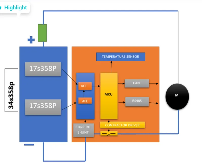
The Battery Management System (BMS) is a critical component of the battery pack and is responsible for monitoring and controlling the battery pack to ensure safe and efficient operation. The BMS topology for this battery pack could be as follows:
- Each cell in the battery pack is monitored by a dedicated cell monitoring board, which measures the voltage and temperature of the cell.
- The cell monitoring boards are connected to a central monitoring and control unit, which aggregates the data and communicates with the vehicle's control system.
- The central monitoring and control unit also manages the charging and discharging of the battery pack, using a high-power charger and a DC-DC converter to interface with the vehicle's electrical system.
- The BMS includes safety features, such as overvoltage and undervoltage protection, overcurrent protection, and thermal management systems to prevent the battery from overheating.
- In addition, the BMS may also include a state-of-charge (SoC) estimation algorithm to estimate the remaining charge in the battery pack and a cell balancing algorithm to equalize the charge across all cells in the pack.
The BMS topology for this battery pack can be designed as follows:
-
Cell monitoring: Each cell in the pack must be monitored continuously to detect any potential failures, such as over-voltage, under-voltage, and over-temperature. To achieve this, a dedicated battery monitoring IC should be used to monitor each cell's voltage, temperature, and state of charge.
-
Balancing: To ensure that all cells in the pack are charged and discharged evenly, a balancing system should be implemented. The balancing system can be passive or active, and its purpose is to equalize the voltage of each cell by bleeding off the excess charge from the fully charged cells.
-
Current monitoring: To measure the current flowing in and out of the battery pack, a current sensor should be integrated into the system. This information can be used to determine the state of charge of the battery pack accurately.
-
Temperature monitoring: Temperature sensors should be integrated into the system to measure the temperature of the battery pack. This information can be used to prevent overheating and ensure safe operation.
-
Safety features: A BMS should include safety features to prevent accidents or damage to the battery pack. These safety features can include over-current protection, over-voltage protection, and under-voltage protection.
-
Communication: The BMS should be able to communicate with the vehicle's main control unit to provide data on the battery pack's state of health and performance.
Battery pack of this size and complexity, a modular decentralized BMS topology would be a suitable choice.A modular BMS is a combination of the above two topologies. This arrangement is also known as decentralized, star, or the master and slaves topology
In a modular decentralized BMS topology, each cell or group of cells has its own BMS module, which monitors and controls the cell voltage, current, and temperature. These individual BMS modules are connected to a central control module, which receives data from all the modules and provides overall system control and monitoring.
This topology offers several advantages, such as increased reliability, scalability, and flexibility. The modular design allows for easy replacement of individual modules, minimizing downtime in case of a fault. Decentralization also reduces the impact of a single point of failure, as any failures are contained within a single module rather than affecting the entire system.
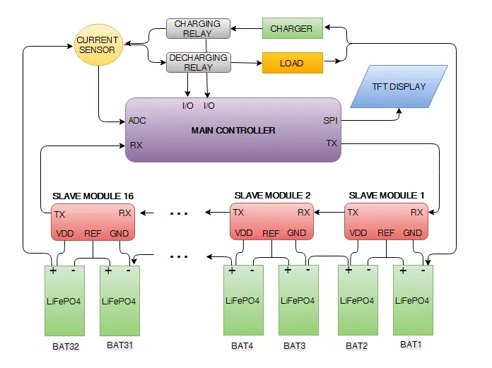
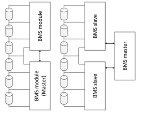
Additionally, the decentralized approach allows for easy expansion of the system by simply adding more modules, making it a suitable choice for a large and complex battery pack such as one used in an electric car.
Overall, a modular decentralized BMS topology is a robust and flexible solution for managing the battery pack in an electric car, ensuring its safe and efficient operation.
2. Build a 3S2P battery pack configuration with generic battery block using Matlab/Simulink.
To build a 3S2P battery pack configuration with a generic battery block using Matlab/Simulink:
-
Open Matlab/Simulink and create a new model.
-
From the Simulink Library Browser, drag and drop a "Generic Battery" block onto the model canvas.
-
Double-click the "Generic Battery" block to open its Block Parameters dialog box.
-
In the Block Parameters dialog box, set the "Battery Type" parameter to "Custom".
-
Set the "Number of Cells in Series" parameter to 3 and the "Number of Cells in Parallel" parameter to 2.
-
Set the "Cell Capacity" parameter to the capacity of the individual battery cells in Ampere-hours (Ah).
-
Set the "Nominal Voltage" parameter to the nominal voltage of the individual battery cells in Volts (V).
-
Set the "Initial State of Charge" parameter to the initial state of charge of the battery pack as a percentage (e.g. 50%).
-
Connect the output of the "Generic Battery" block to a load or other circuit for testing.
-
Save the Simulink model and run the simulation to observe the battery pack behavior.
With these steps, we have successfully built a 3S2P battery pack configuration with a generic battery block using Matlab/Simulink.
Battery Cells :
3 cells in series and 2 cells in parallel connection.
Hence the total number of cells in the battery pack is = 3*2 = 6 cells in the battery pack.
The design of a battery pack involves connecting individual cells in a configuration that meets the desired specifications. In this case, we have three cells connected in series and two in parallel. The nominal cell voltage is 7.2 volts, the rated capacity is 5.4 Ah, and the maximum voltage is 8.3 volts.
Simulink Model:
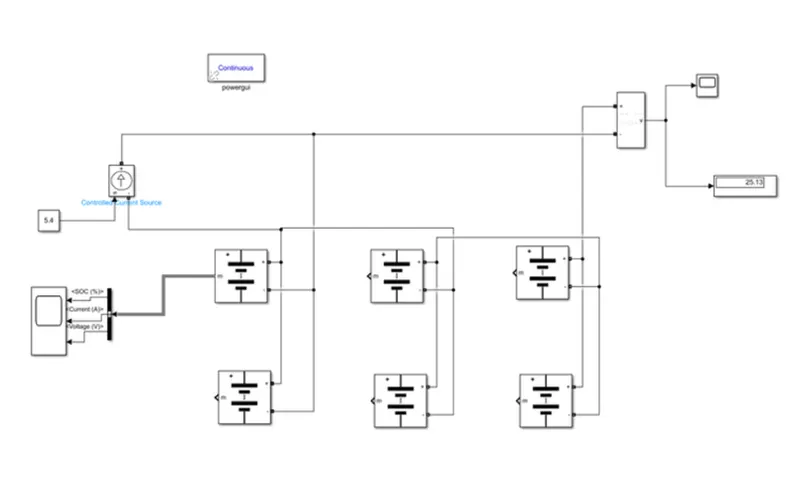
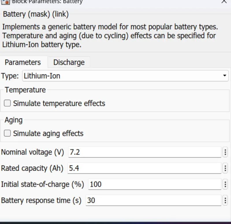
Using these parameters, we can calculate the nominal voltage of the battery pack to be 21.6 volts and the rated capacity to be 10.8 Ah.
The overall voltage of the battery pack is 24.9 volts or 25 volts.
To connect the cells, we connect the positive terminal of one cell to the positive terminal of the next cell in parallel, and the negative terminal to the negative terminal.
For series connection, we connect the positive terminal of one cell to the negative terminal of the next cell.
We use a Scope block to monitor the state of charge (SOC) of the battery and a Voltage Measurement block to measure the voltage.
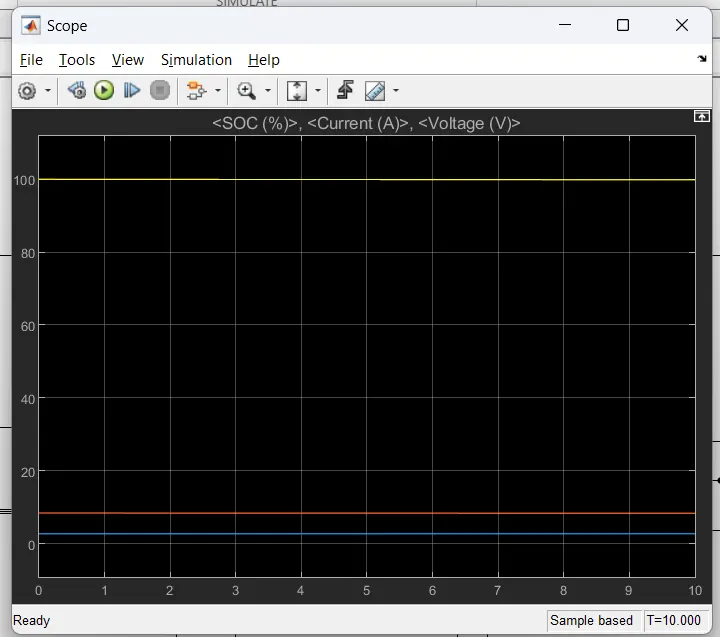
To control the current, we use a Current Control Source block that converts the input signal to an equivalent current source.
The output signal of the Voltage Measurement block is disabled when not used in a phasor simulation, which can be activated by a Powergui block.
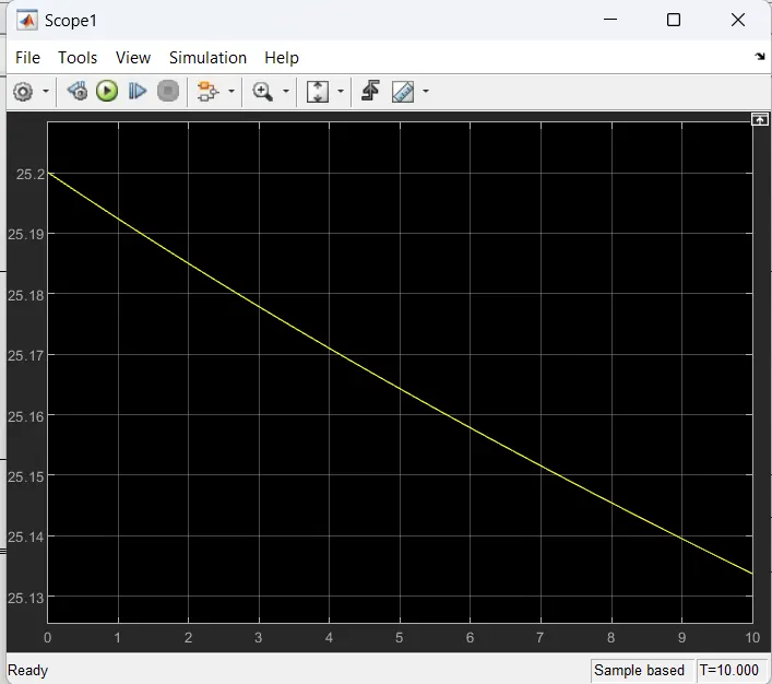
Finally, we can use the Matlab Simulink model to plot the output waveform and verify that the battery pack configuration meets the desired specifications.