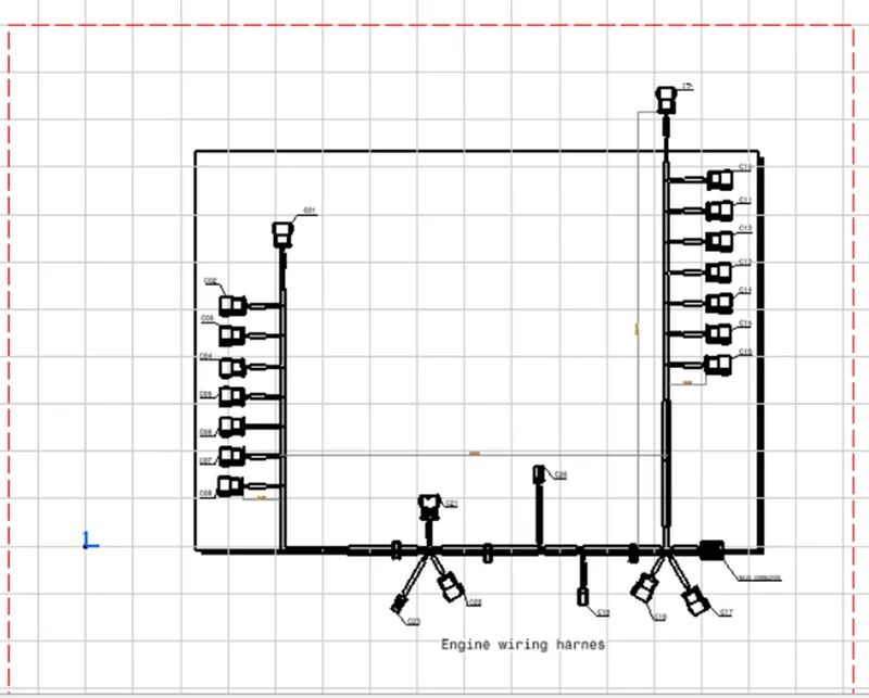
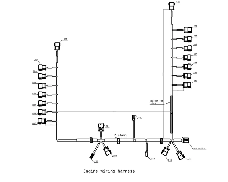
Project 1
Automatic wiring harness design using catia v5
Aim:
Route the Wiring harness on Given Engine and Prepare flatten view drawing in CATIA V5. Application of all Packaging rules, Industry best practices studied in this course shall be demonstrated in design. Apply Protection coverings as required.
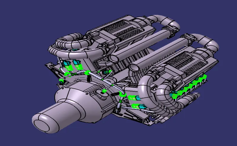
The given engine assembly shown below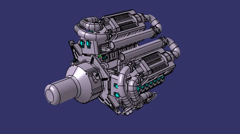
A V16 engine is a sixteen-cylinder piston engine where two banks of eight cylinders are arranged in a V configuration around a common crankshaft. V16 engines are less common than engines with fewer cylinders, such as V8 and V12 engines. Each bank of a V16 engine can be thought of as a straight-8, a design that can be inherently balanced. Most V16 engines have a 45° bank angle.
Step 1 : analysis the engine configuration
This report aims to provide a detailed design of the wiring harness for a V16 engine that has 23 connectors. The wiring harness is a critical component that connects various electrical and electronic components in the engine. The V16 engine is a high-performance engine used in many applications, including racing cars, marine engines, and power generators. The wiring harness design needs to ensure that all the components are correctly connected and function efficiently.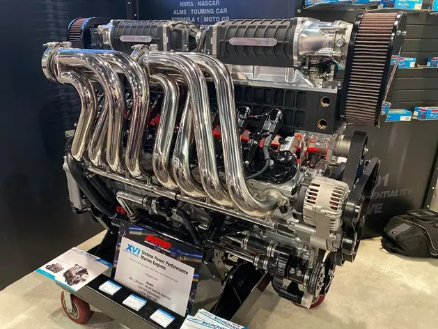
Step2: design requirements
The design requirements for the V16 engine wiring harness are as follows:
- The wiring harness must have 23 connectors to connect all the electrical and electronic components in the engine.
- The wiring harness must be designed to withstand high temperatures and vibrations.
- The wiring harness must be easy to install and remove for maintenance purposes.
- The wiring harness must be organized in a way that ensures easy identification of the connections and avoids any confusion during installation.
- The wiring harness must be designed to prevent any interference between the wires to avoid signal noise and ensure reliable communication between the components.
Step3: design approach
To meet the design requirements, the wiring harness will be designed with the following approach:
- Connector Selection: The wiring harness will use high-quality connectors to ensure reliable connections between the components. The connectors will be selected based on their size, shape, and durability.
- Wire Selection: The wires used in the harness will be selected based on their current carrying capacity, temperature rating, and resistance to vibration.
- Routing: The routing of the wires will be carefully planned to ensure that there is no interference between the wires, and the harness is organized and easy to install.
- Labeling: Each wire in the harness will be labeled to ensure easy identification during installation and maintenance.
- Testing: The wiring harness will be tested to ensure that all connections are correct and that there is no signal noise or interference.
Step 4: connector selection
The V16 engine wiring harness will have 23 connectors, which will be connected to various components in the engine, including the fuel injectors, ignition system, sensors, and actuators. The wiring harness will be made of high-quality wires with a temperature rating of up to 125°C to ensure that they can withstand high temperatures.
In this design no requirement is advised to select the connector or no data for the connector used in particular place.
So we select the connector our self for the engine.
There is no data for the connector requirements I select the following connectors for design the connector.
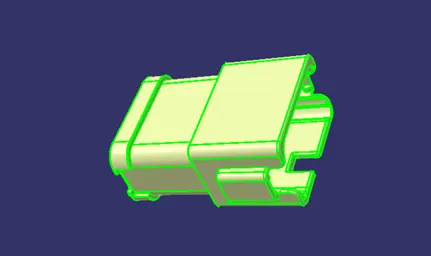
The above connector is used for fuel injectors. Fuel injector is one of the main components in the engine the signal for the fuel injector is very important to run the engine so we select the connector as a faill proof in running.
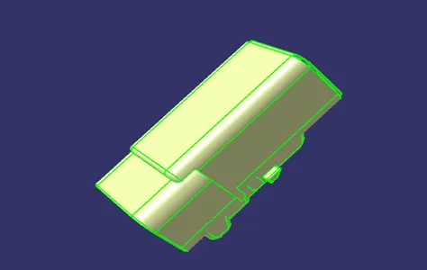
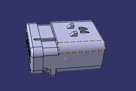
The other connectors used in the wiring harness are
Step 5: wire selection
Each wire in the harness will be labeled with its function, color, and connection point to ensure easy identification during installation and maintenance. The labels will be made of durable material to ensure that they do not fade or wear off over time.
Step 6: routing
Before routing we suppose to select the routing path and the suitable clamping devices.
The following types of clamping devices are commonly used.
P-clamp:
A P-clamp, also known as a loop clamp, is a type of clamp used in wiring harnesses to secure and organize wires or cables. It is called a P clamp because of its shape, which resembles the letter "P." P clamps are commonly used in automotive and aerospace industries, where wiring harnesses are essential for electrical systems.

The primary purpose of P clamps is to hold wires or cables securely in place, preventing them from rubbing against each other or other components in the system. When wires rub against each other or other parts of the system, it can cause abrasion and wear, leading to short circuits or other electrical problems.
P clamps are typically made of metal or plastic and come in various sizes to accommodate different wire diameters. They have a loop-shaped design that allows the wire to be easily inserted and secured in place. The clamp is then fastened to the surface using a screw, bolt, or rivet.
Cable Ties:
Also known as zip ties, cable ties are plastic strips that can be wrapped around a bundle of wires and pulled tight to hold them in place. Cable ties come in various lengths and strengths and are widely used in automotive and aerospace industries.

Grommets:
Grommets are rubber or plastic inserts that are used to protect wires and cables as they pass through a hole in a surface. They provide insulation and prevent abrasion, reducing the risk of electrical shorts.

Fir tree clip:
A fir tree clip, also known as a Christmas tree clip, is a type of clip used in wiring harnesses to secure wires and cables to a surface or panel. It is called a fir tree clip because of its shape, which resembles a fir tree or Christmas tree.
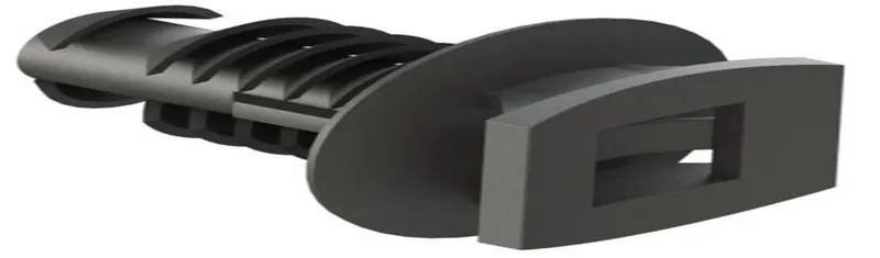
Fir tree clips are widely used in the automotive industry, where they are used to secure wiring harnesses to body panels, engine components, and other parts of the vehicle. They are also used in the aerospace industry, where they are used to secure wiring harnesses to aircraft fuselages and other structures.
Mounting channels:
Mounting channels are used in wiring harnesses to secure and organize wires and cables in a specific configuration. It can be used in a variety of applications, including automotive, aerospace, and industrial settings. They are particularly useful in applications where a large number of wires and cables need to be organized and secured in a specific configuration.
One of the main advantages of mounting channels is that they provide a high degree of flexibility in terms of wire routing and configuration. Wires can be easily added or removed from the channel as needed, and the channel can be cut to the desired length to accommodate specific wiring configurations.
Step 7: Assemble the connectors
The connectors are selected so they need to assemble into the engine assembly
Before goes to the assembly we need to create a separate product file for the wiring harness and for the engine assembly
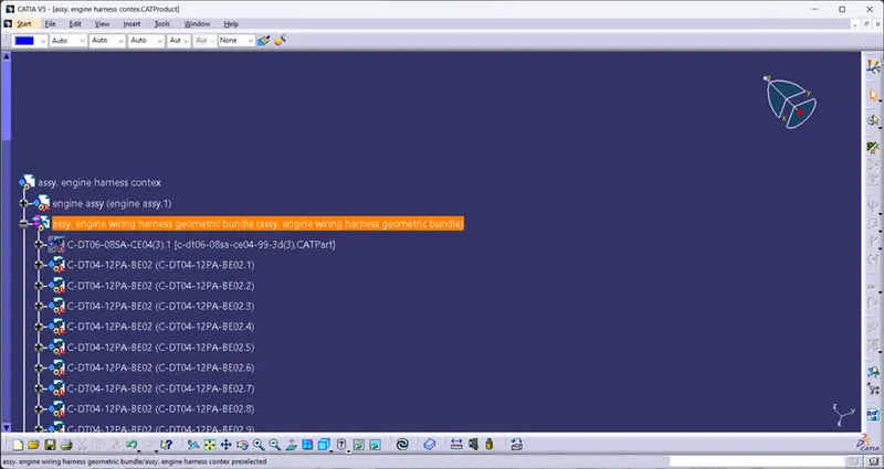
Then copy paste or add the connector file in to the product file.
Assemble the connectors in its place as required by using manipulation and smart move in assembly work bench.
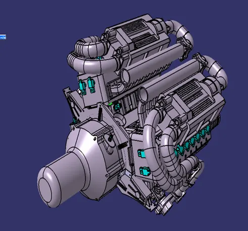
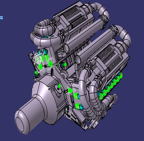
Step 8: Define the routing path
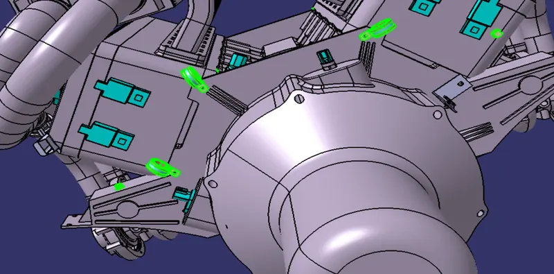
The connectors are placed in its place we supposed to do design the routing path we place the clamps and clips to carry the wiring harness throughout the engine.
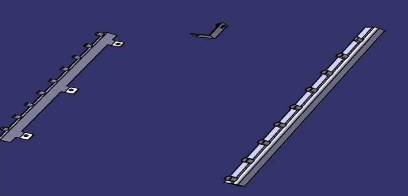
Step 9: Providing the mounding channel
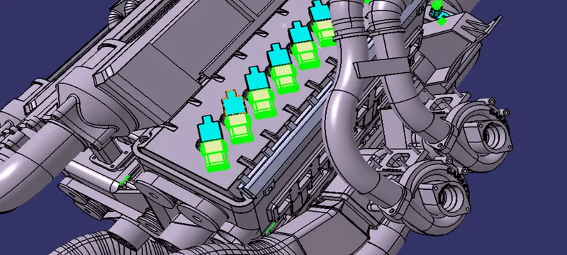
Provide the mounding channel for fuel injector have many connectors. So avoid using many clips and clamp in this place.
Step 10: Route the wire
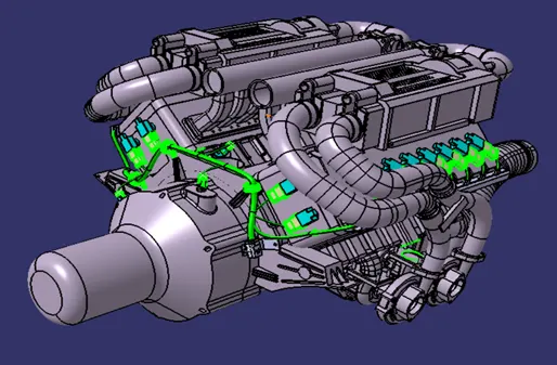
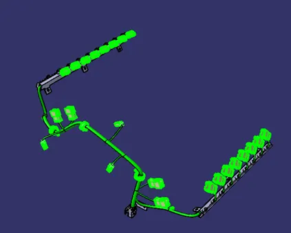
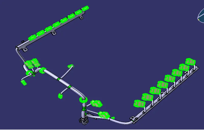
Route the wiring harness throughout the engine
Step11: provide appropriate production devices
Provide the production devices for the wiring harness to product from heat and other obstacle.
Step12: Flatting the harness assembly
In the context of wiring harnesses, "flatting" refers to the process of flattening and organizing multiple wires or cables into a flat, ribbon-like configuration. This is typically done to make the wiring harness more compact and easier to manage, especially in situations where space is limited or where the wires need to be routed around tight corners or through narrow channels.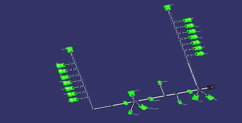
The process of flatting typically involves laying out the wires or cables side by side and then using a special tool, such as a wire harness flattener or a cable tie, to hold them in place and maintain their flat configuration. The flattened wires can then be secured to the chassis or other structures using various types of fasteners, such as clips or adhesives. Flatting can also be used to create multi-layer wiring harnesses, where multiple layers of flat wires are stacked on top of each other to save space and reduce the overall profile of the harness.
Step 13: Drafting
Drafting in wiring harness refers to the process of creating a detailed technical drawing or diagram that represents the layout and connections of the wires and components in a wiring harness. This drawing typically includes information such as wire sizes, color codes, connector types, and pin locations, and it serves as a blueprint for the manufacturing and assembly of the wiring harness. Drafting is an important part of the design and engineering process for wiring harnesses, as it ensures that the final product meets the required specifications and standards, and is safe and reliable for its intended use.