Project 1
1. Design a multi-storey Residential Building located in Bangalore using STAAD Pro Connect Edition. The specification must be as follows:
|
Building floors |
G + 6 + R |
|
Plan dimension |
B = 25m , L = 16m |
|
Storey Height |
h = 3.5m |
|
Soil |
Hard soil |
|
Use |
Residential Purpose |
|
Safe Bearing Capacity |
180 kN/m2 |
|
Maximum slab thickness |
150mm |
Assume suitable sections for structural elements. Follow IS456, IS1893 and IS 875
- Prepare a Design Basis Report for the project
- Create structural model using STAAD Pro Connect Edition
- Prepare DL, LL, WL and EQL load calculations as per IS 875 standards
- Design slab element using MS – Excel
- Design beam and column element using STAAD RCDC. Attach the design calculation report.
- Design Foundations using STAAD Foundation.
- Prepare bar bending schedule for beam and column using STAAD RCDC
- Attach necessary sketches and drawings wherever required.
- All stipulations, assumptions and design parameter must adhere to Indian Standards.
. Design a Warehouse Building located in Chennai using STAAD Pro Connect Edition. The specification must be as follows
Assume suitable sections for structural elements. Follow IS800:2007, IS1893 and IS 875
- Prepare a Design Basis Report for the project
- Create structural model using STAAD Pro Connect Edition
- Prepare DL, LL, WL and EQL load calculations as per IS 875 standards
- Design using MS – Excel
- Steel column
- Rafter
- Base plate
- Pedestal
- Z- purlin
- Design Foundations using STAAD Foundation.
- Attach necessary sketches and drawings wherever required.
- All stipulations, assumptions and design parameter must adhere to Indian Standards.
- To calculate the wind pressure and sesimic load cases first we need to calculate the centre height of the sturucture given that the slope roof is 1 in 10 then center height of the structure is calculated as
- x/20=1/10 then x=2
- then the centre height = clear height + slope height = 10+2 = 12
Step-2:
- open stadd pro and create new project in that select the units as metric then the stadd model will appear.
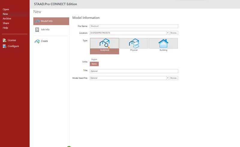
- Given the structural modal of an industrial building dimensions and considerations are
Width = 40m
Height = 10m
Length = 80m
Bay spacing = 6m
Location = Mumbai
Soil Type = Hard
- Then create a model by modal displacement method and enter the origin as (0,0) and also enter the nodes (40,0),(0,10),(40,0) nodes for the creating the modal.
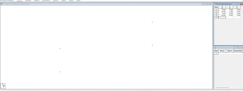
- and next go to the geomentry window in that go to cerate beam or add beam option and add beam in the given nodes.
- create a node at the centre from the right support then consider the height of the node will be centre height of the structure and in the middle of the span of the two beams ie (20,12).
- add the beam from the node to the center point.
- create a another nodes at the center and add beam.
- To have a two evenly spaced nodes in between select the beam and go to the Insert node option In that give the value of n=2 for two nodes which are equally spaced.
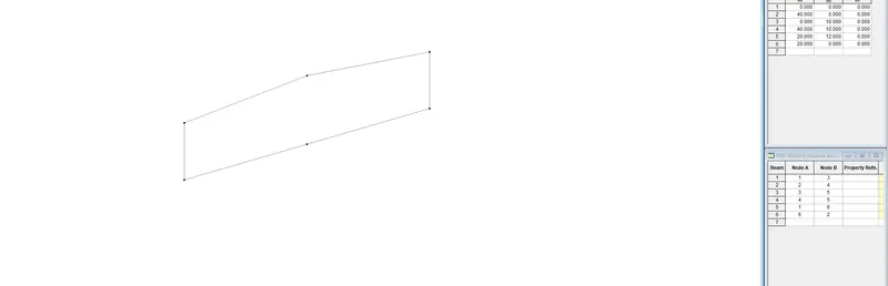
- add beams to the given nodes and to have a perpendicular Intersections go to add beam options in that we have a option of perpendicular intersections and click on that option and add beams at the nodes.
- and copy the nodes and paste it at height of 12m and add beams by add beam option.
- To stop the beams at the intersecton of the frames, select the beams and go for the intersecting beams option in that click on intersect the selected beams option and give Tolerance as "0" and click ok.
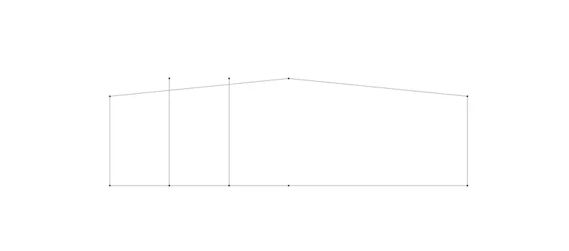
- remove the unwanted beams and add the beams at the center.
- Now replicate the middle beams to the next side to replicate the beams go to mirror option select the beams at click on to the referene plane node to replicate at that point.
- then next step is repliacte the main frame alone.select the beam members and select the beams present in the main frame,
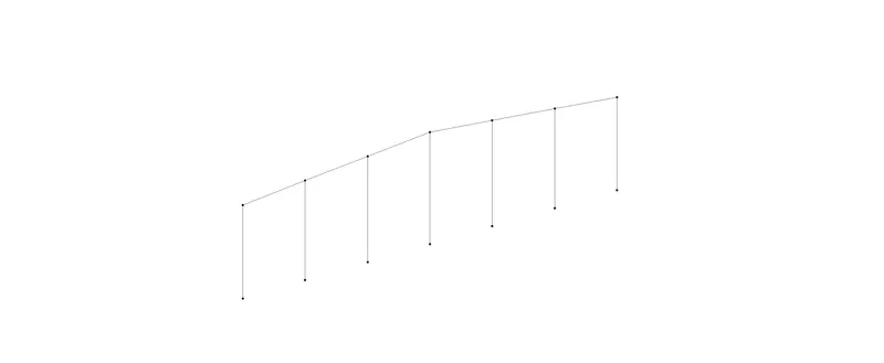
- select the beam members and select the beams present in the main frame, go to transilational repeat option In that select the options ie, repeat in z-directon, bay spacing-6m, and number of steps =12, and click on link steps and open base option and click on ok.
- the number of steps depend upon length.
- select the frames at the end and make transilational repeat of 80m at the end of the structure ie, the start and end point of the structure will be same.
- add the required beams by add beams option.
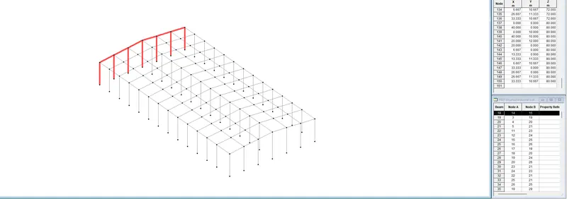
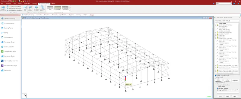
- 3D model is created and chck the dimensions by node to node distence option.
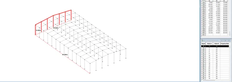
- add all bracings that required in the structral spacing and rafters as per the structural spacing.
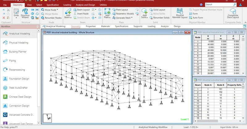
- give the supports as fixed supports for the bottom of the coloumn ie the cloumn edge footing is should be fixed.
- add the required beams ie plinth beam and the bracing by the add beam option.
- add and remove unwanted beams and columns the add beams option and delete by delete option.
- 3D model is created and supports is given as per requirement.
Step-3: Assigning properties:
- At the property section in that section we should define the properties in the given columns.
- In the property section go to define properties and in that select the I section In that I section give the values as per the required column sizes.
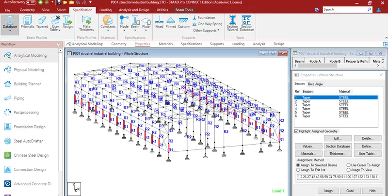
- there will be different sections like R1,R2,R3,R4,R5,R6 as the tappered section in that section give the values as per the requirement.
- assign the properties as per the given requirement
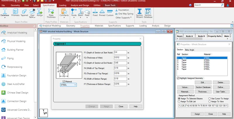
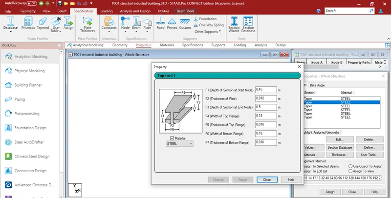
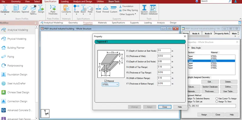
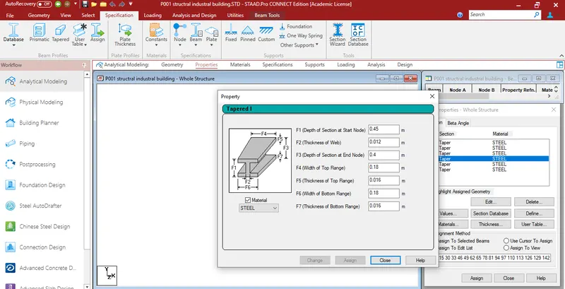
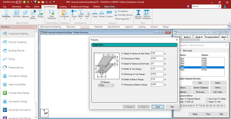
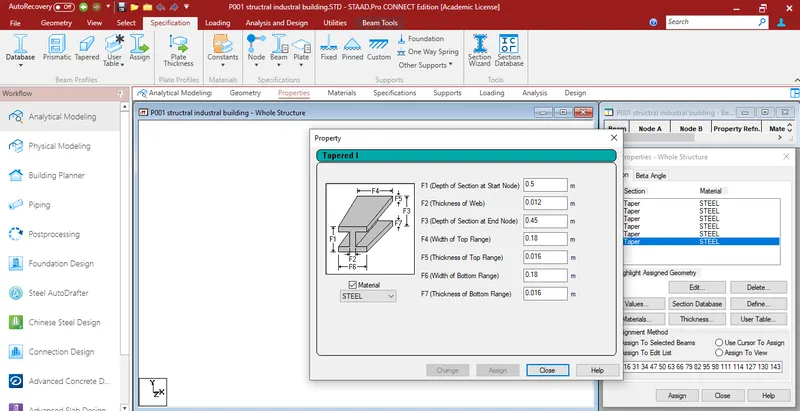
- assign the properties and add the required properties as a steel structure and Is code book and select the beams and assign to the given beams
Step-4: Assigning the loads:
- To assign the load we must first define the loads and its properties that shuold be assign
- we should add sesmic and wind load properties for that we should have to assign load definations.
- To assign the sesmic properties go to add new loading tab in that assign and define sesmic definations then add and give the required properties as per the structure.
- give the values fo zone factor and time period that the we calculate as per the structure given and give all the values asper Is code book.
- assign the properties and add the required properties as a steel structure and Is code book and select the beams and assign to the given beams
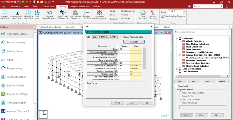
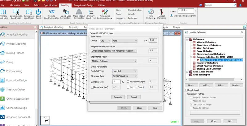
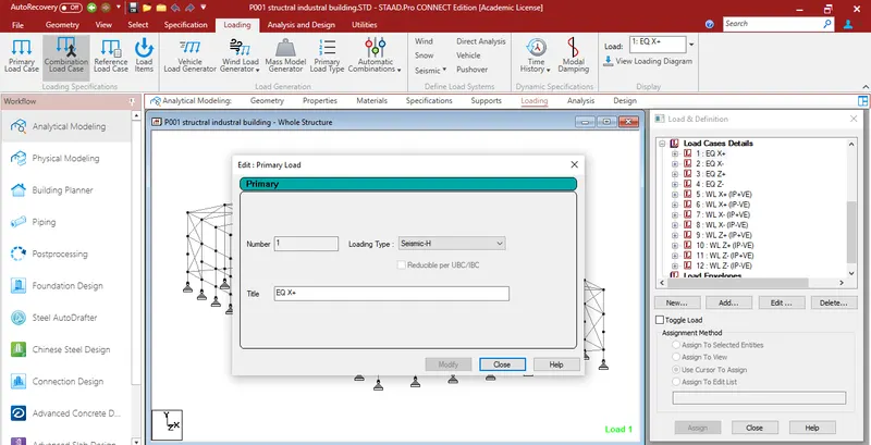
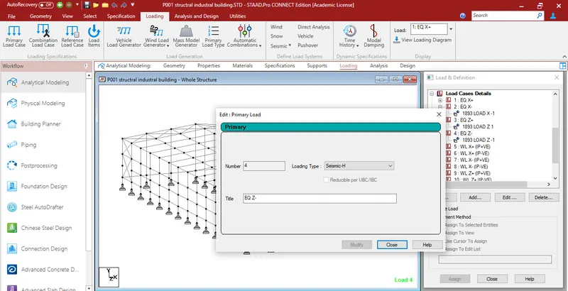
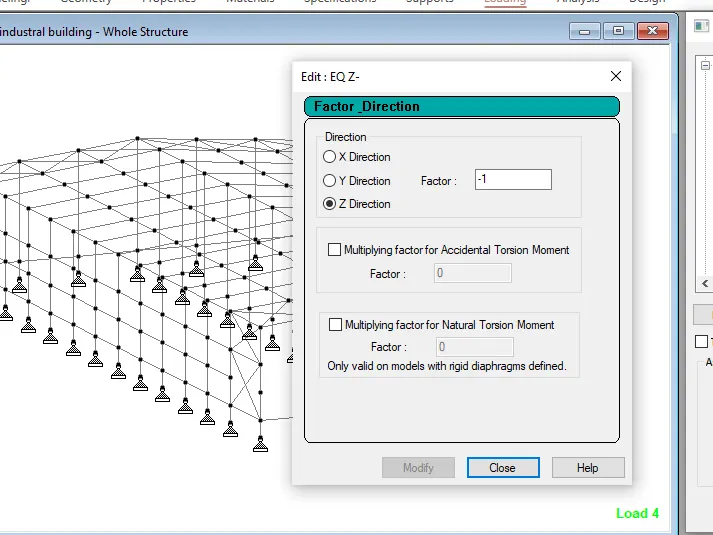
- Define load casses in that load casses we should assign the earthquake load in X and z direction in the posituve and negative direction.
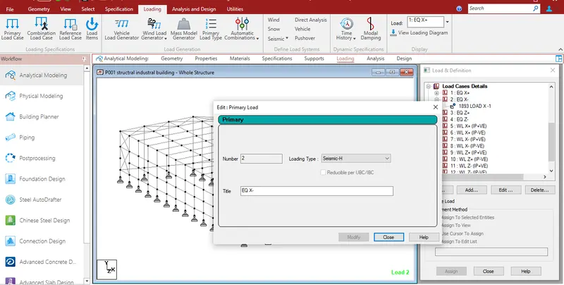
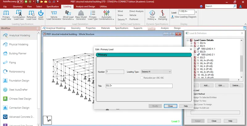
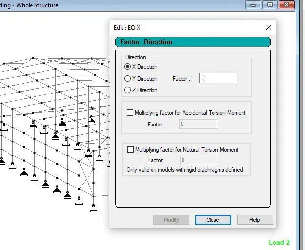
- so define and add X+,X-,Z+,Z- in the direction of the as per the given structural direction.
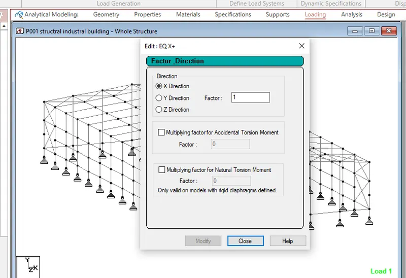
- In the X+ direction give the specific values as per given structure zone factor and direction of the load which is acting on the structure.
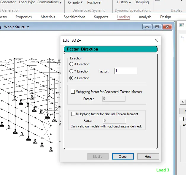
- similarly in the Z direction also give the values of the zone factore defination and then load which is acting on the structure.
- Define load casses in that load casses we should assign the earthquake load in X and z direction in the posituve and negative direction.
- so define and add X+,X-,Z+,Z- in the direction of the as per the given structural direction.
- In the X+ direction give the specific values as per given structure zone factor and direction of the load which is acting on the structure.
- similarly in the Z direction also give the values of the zone factore defination and then load which is acting on the structure.
- To apply wind load to the given structure go to load case details and go to add option In that add 8 load casses
- +ve X direction with +ve Int pressure
- +ve X direction with -ve Int pressure
- -ve X direction with +ve Int presssure
- -ve X direction with -ve Int pressure
- +ve Z direction with +ve Int pressure
- +ve Z direction with -ve Int pressure
- -ve Z direction with +ve Int pressure
- -ve Z direction with -ve Int pressure
- after adding all the conditions takien to the structure add the values that calculated in each case according to the structure for that go to the each and every load casses.
- select the +ve X direction with +ve Int pressure case and go to add option after that member load and enter the value that we calculated in each and every direction and add the values according to the structure.
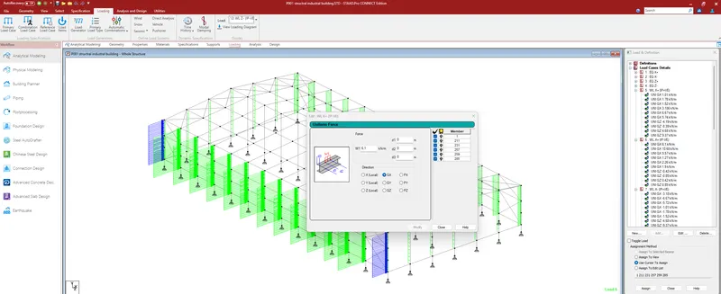
- similarly add all the load casses that we calculated according to the structure and then
- select the values and column and click on assign to the selected beams option and assign
- similarly continue to all the casses that we added to the structure.
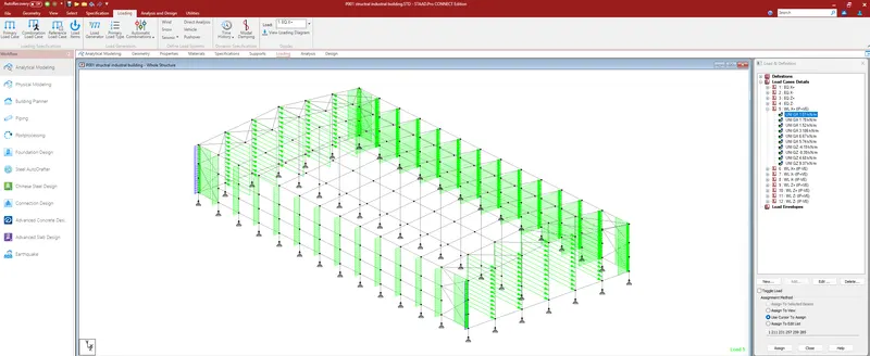
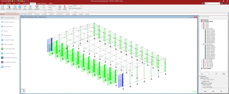
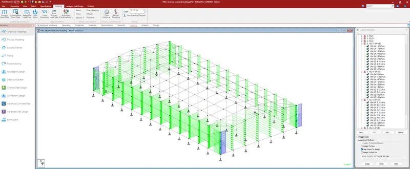
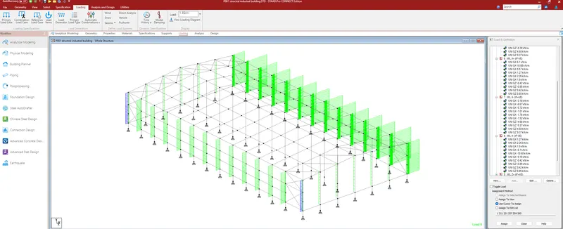
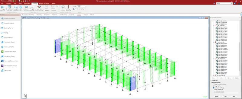
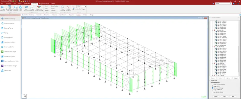
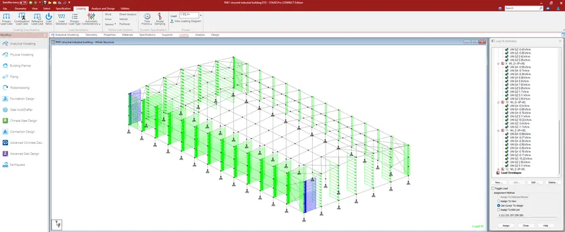
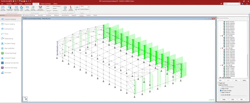
- In the given process we can add sesmic and wind load to the given structure in stadd pro
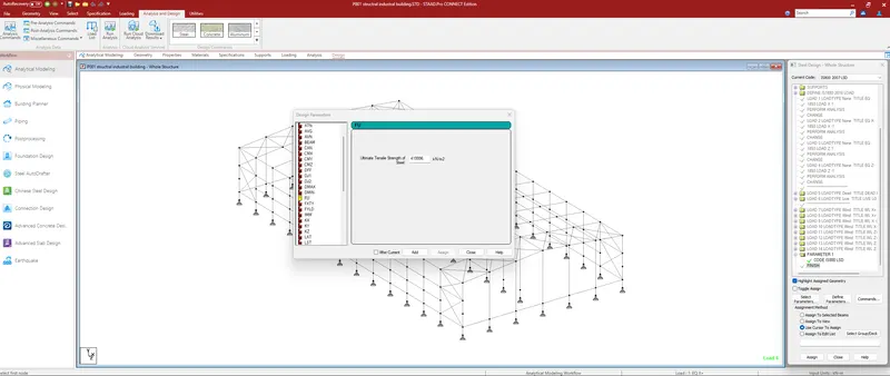
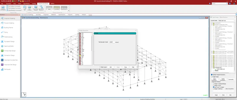
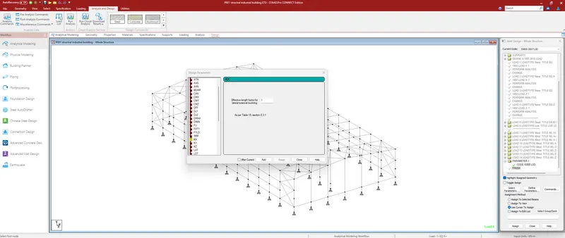
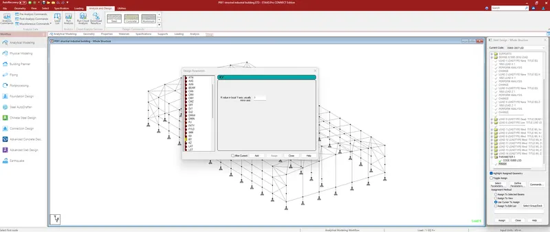
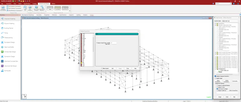
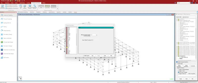
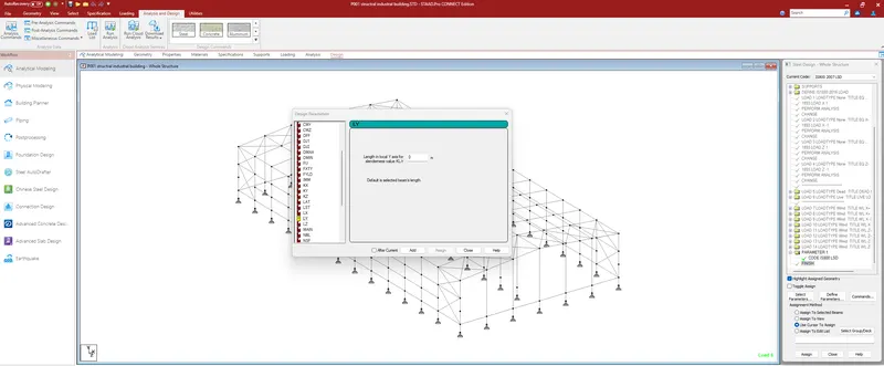
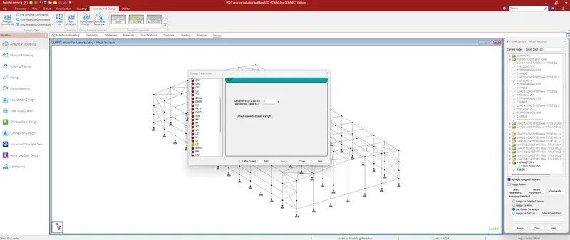
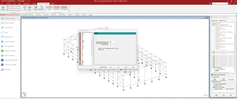
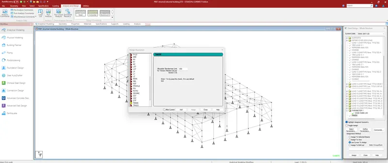
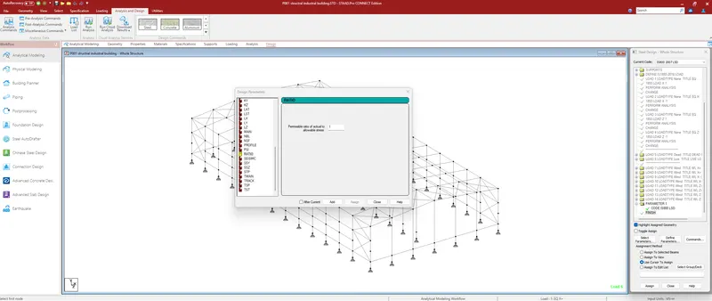
- go to design parameters in that click on design parameters option in that select the options