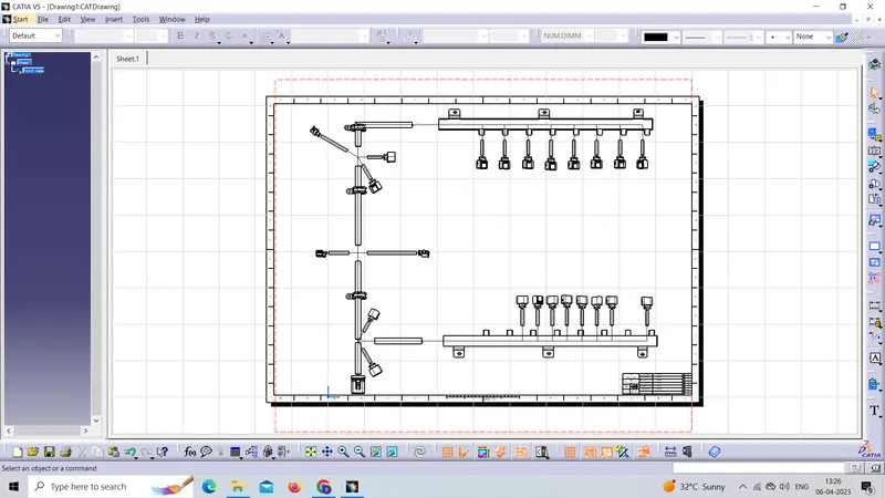
Project 1
The project's objective is to route the wiring harness on the given Engine shown below and prepare a flattened view drawing in CATIA V5. All types of packaging rules have to be considered while routing the harness. Also, Industry best practices should be demonstrated in design. All the necessary details like clearance, clipping/clamping selection, harness fixing requirements, and harness continuity should be provided to design a wiring harness.
Step 1: Creating Context Assembly
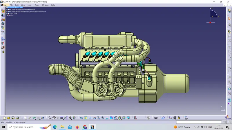
A Context Assembly will contain Engine Assembly data and Assy_Engine_Harness_Geometrical.
If any sheet metal bracket will require then they are added in the context assembly.
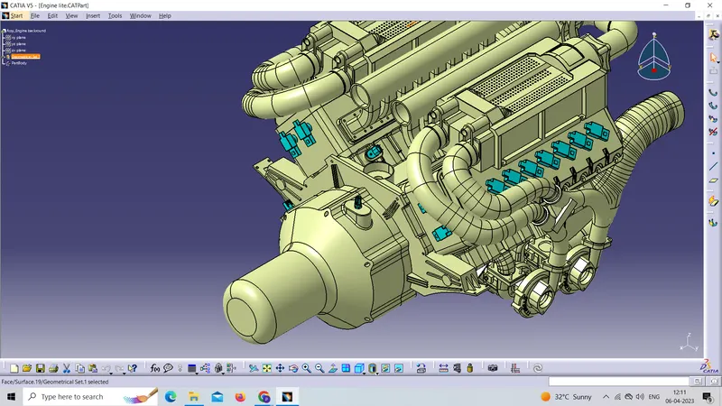
Step 2: To define the electric properties of the part which are used for routing the wiring connector
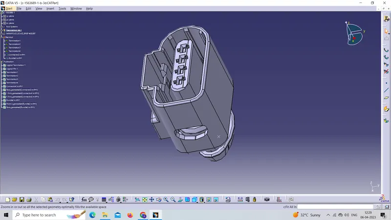
4 pole connector which is placed on the engine manifold is also used to connect the cam sensor
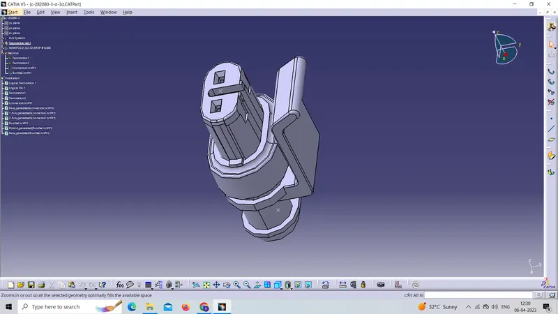
2pole connector
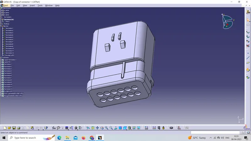
12 pole interconnection from this connector our routing is start
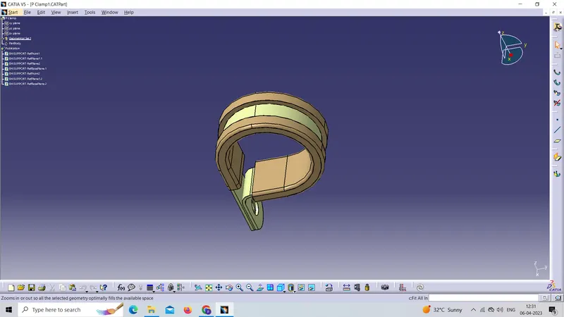
p clamps
Step 3: Now place the above-defined parts at the desired location and start defining the routing
Step 4: Add protective covering
here I used corrugated tubes for the main bundle segment which id is 15mm & cotton tapes for the sub-branches which is 7mm
Step 5: After defining routing & Add protective covering check the bundled connectivity
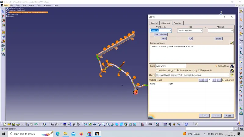
In this step, first we have to make sure that multi-branchable is selected then we have to go to Edit>Search>Advanced>Workbench-Electrical>Type-Bundle Segment>Attribute-Fully Connected
By selecting the 'True' option will show all the connected bundle segments while selecting the 'False' option will show all the non-connected bundle segments.
Here, we have selected the 'True' option and searched for results. All the bundle segments are highlighted found showing that all the bundle segments are electrically connected
now by using electrical harness flattening we can straighten or flatten all the wires connected with the connectors.
Step 6: After checking the bundled connectivity now we are doing flattening
for flattening we have to create a product file then we have to define the flattening parameters After defining the flattening parameters commands are activated click on the extract command then click on the geometric file which we have to flatten after clicking the geometric file is coming in the flattening file then click on flatten command then select the plane on which we have to flatten and then click on the branch then select all then click ok
Before Flattening
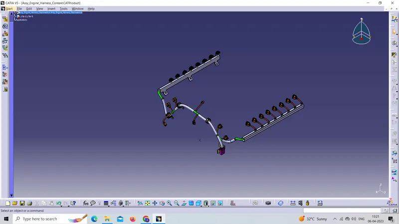
After Flattening
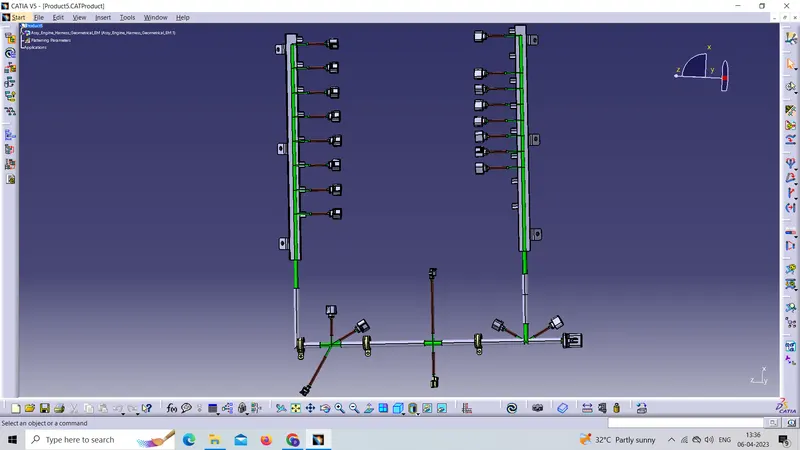
drawing view of flattening
for drawing, we have created a new drawing file