Project 1
WIRINING HARNESS ROUTING OF ENGINE
INTRODUCTION:
The automotive wiring harness is referred to as the central nervous system in the vehicle. It mainly consists of an electrical harness and the mechanical harness in the design. The current project is focused on the mechanical wiring harness and its rules and procedure to be followed while routing in the virtual condition. CATIA V5 electrical workbench is used as the CAD tool for routing the wires in the engine and tailgate components.
DESIGN FLOW OF EDS SYSYTEM:
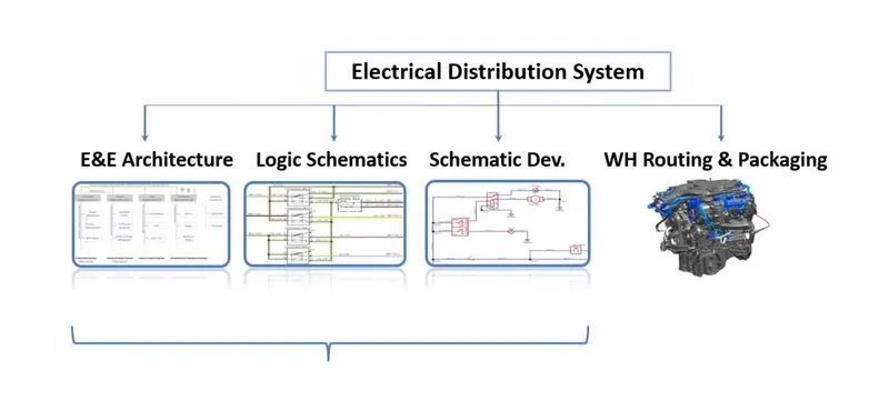
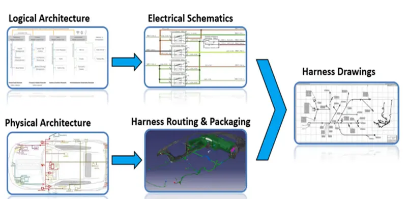
Logical Architecture, Electrical Schematics and Physical Architecture are designed by the electrical department whereas harness Routing and packaging is developed by mechanical department. Upon integration of electrical and mechanical departments final harness drawing is designed.
WIRING HARNESS COMPONENTS:
CONNECTORS:
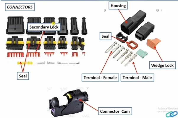
An electrical connector, is an electro-mechanical device used to join Electrical termination and create an electric circuit. Electrical connectors consist of Housing, Terminal, Wedge Locks, Seals, Cavity, Mounting Cam etc., Connectors are plastic moulded housing with locking and retention features
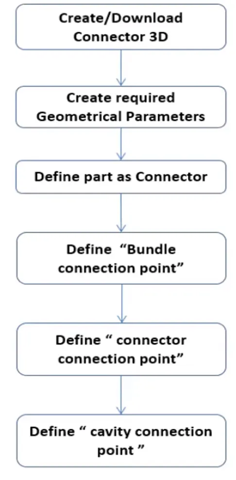
- ELECTRICAL DEFINING PROCEDURE OF CONNECTOR
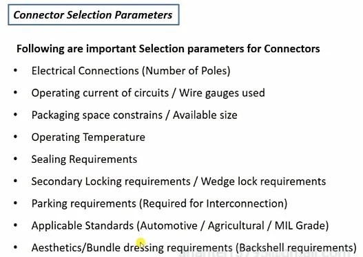
- CONNECTOR SELECTION PARAMETERS
TERMINALS
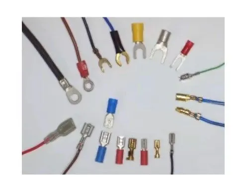
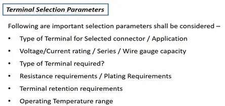
Terminals are defined as “A device designed to terminate a conductor that is to be affixed to a post, stud, chassis, another tongue, etc., to establish an electrical connection.” Terminals are metal (brass) conductor with plating (tin, silver, gold) constructed in specific shape to secure the joint from environmental conditions and with minimum electrical resistance.
WIRE
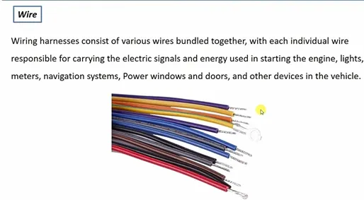
Wire Specifications:
- Standard / Grade
- Current carrying capacity
- Resistance per meter
- Insulation type/ Material
- Colour of Wire
- Temperature rating
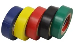
Insulations: are adhesive/non-adhesive tapes and sleeves. They are made from PVC or cotton/polymer materials.
GUIDING CHANNEL
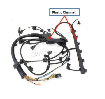
Guiding channels are Plastic moulded or Metal parts designed to guide harness bundle in given geometric area to secure and Protect harness.
CLIPS
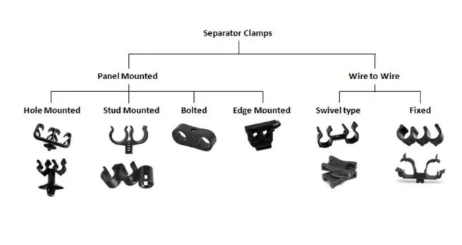
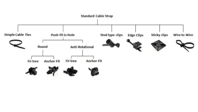
Simple Cable Ties are used in combination with Fir tree or Anchor Fit. Fir tree provides the multi locking while Anchor Fit can be removed with a push force. Stud type clips are simply pushed into the hole. Edge clips are costlier than any other clips and mounted on the panel edges. Sticky clamps are stick to the flat surface of the body. Wire to wire is used to clamp one bundle to the other.
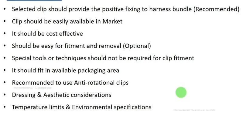
- CLIP SLECTION PARAMETERS
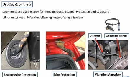
GROMMETS
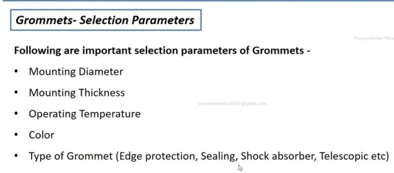
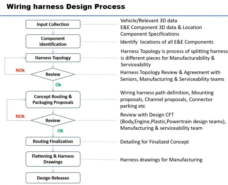
WIRING HARNESS ROUTING DESIGN OF ENGINE
AIM:
To Route the Wiring harness on Given Engine and Prepare flatten view drawing in CATIA V5. Application of all Packaging rules, Industry best practices studied in this course shall be demonstrated in design. Apply Protection coverings as required.
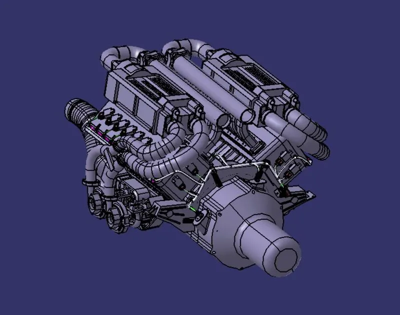
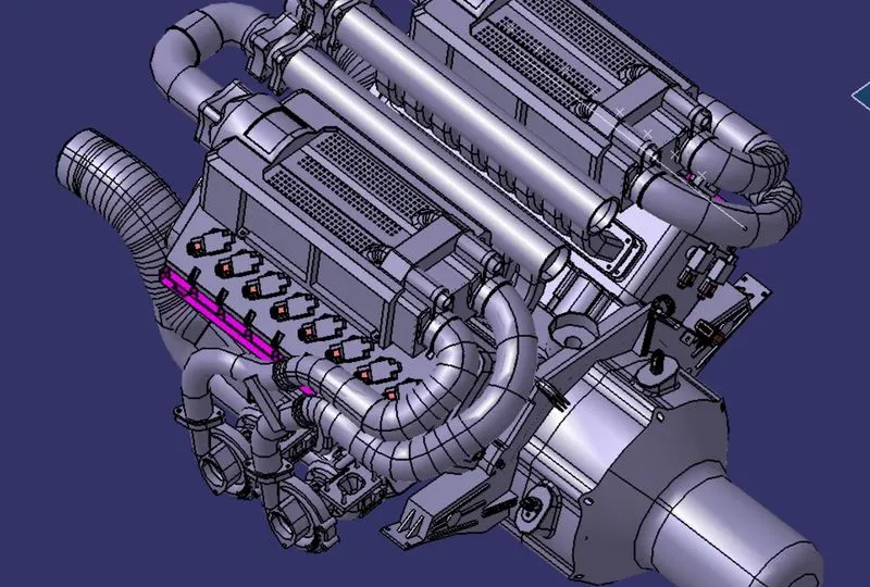
ENGINE PROVIDED:
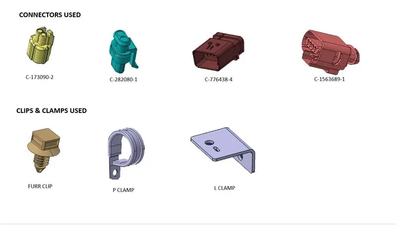
COMMPONENTS USED:
PROCEDURE FOLLOWED:
- Downloaded the engine file
- Identified the components to use
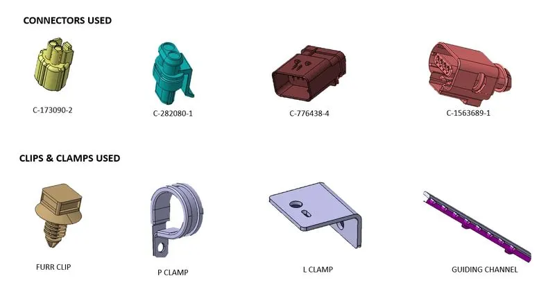
All the connectors are downloaded from te.com and later all are electrically defined and added to the catalog.
Guiding channels are designed as per requirement in routing.
- Arranged of connectors, interconnection connector, clamps and channels
Placed all the connectors and other components in the specified locations of the engine using snap tools.
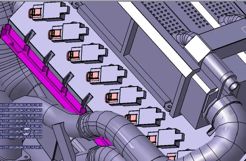
Interconnecting connector placed with the L clamp
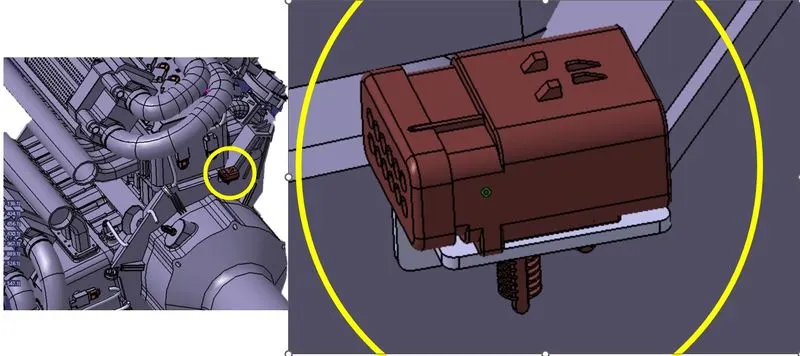
All the components are arranged as per the connection
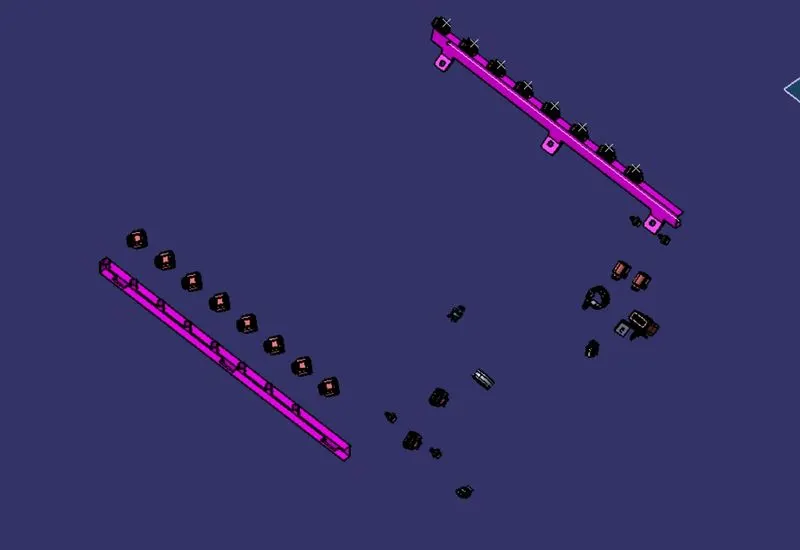
- Created Multi-Branching to the connectors
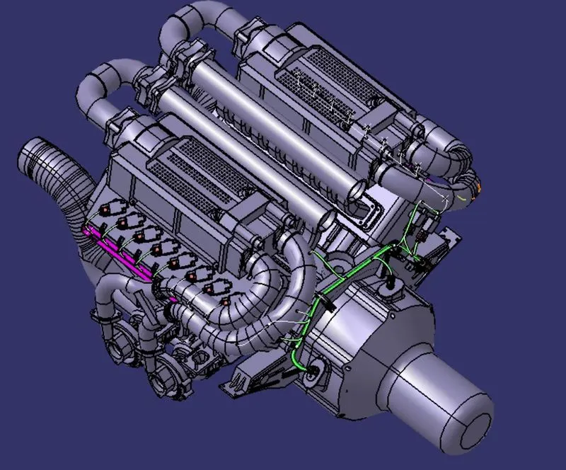
- Applied the protection tube along the buudle segments
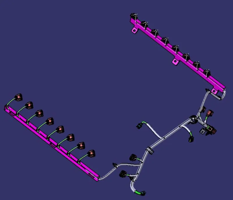
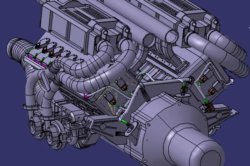
- Wiring harness Routing has been done
- Analysised the bundle segment continuity
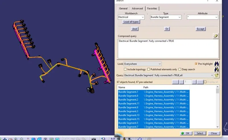
From above search shows that all bundles are connected together.
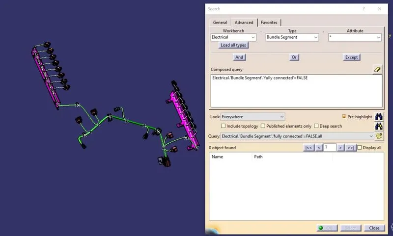
From the search clearly shows that there is no warning between connections of bundle.
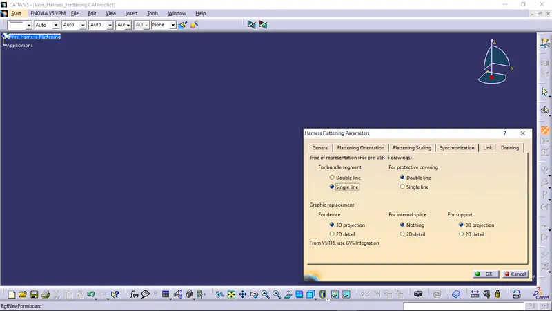
- Defining the HARNESS FLATTENING PARAMETERS
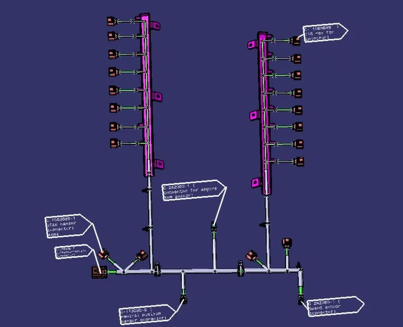
- EXTRACTING THE HARNESS ASSEMBLY AND FLATTEN
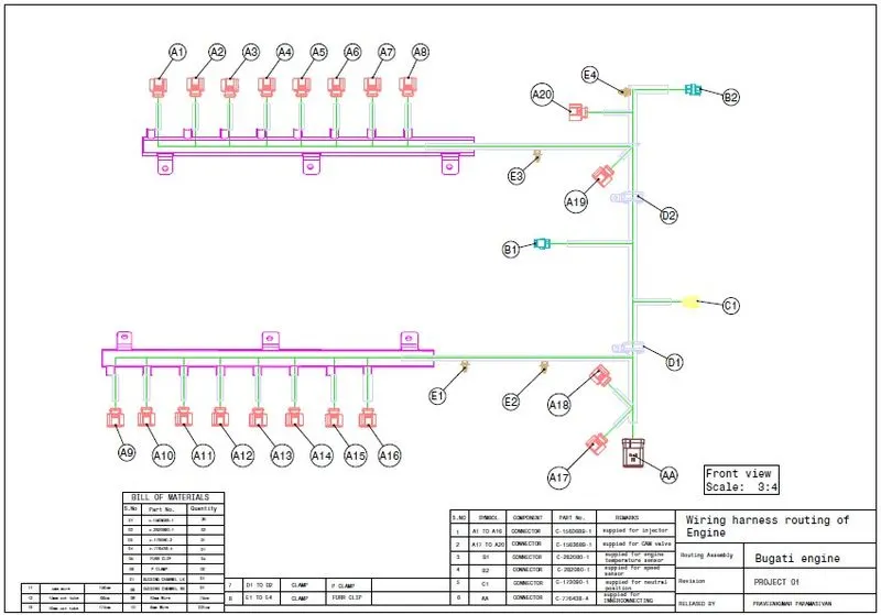
- DRAFTING THE FLATTENED ASSEMBLY
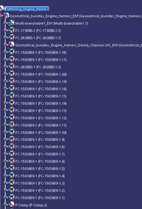
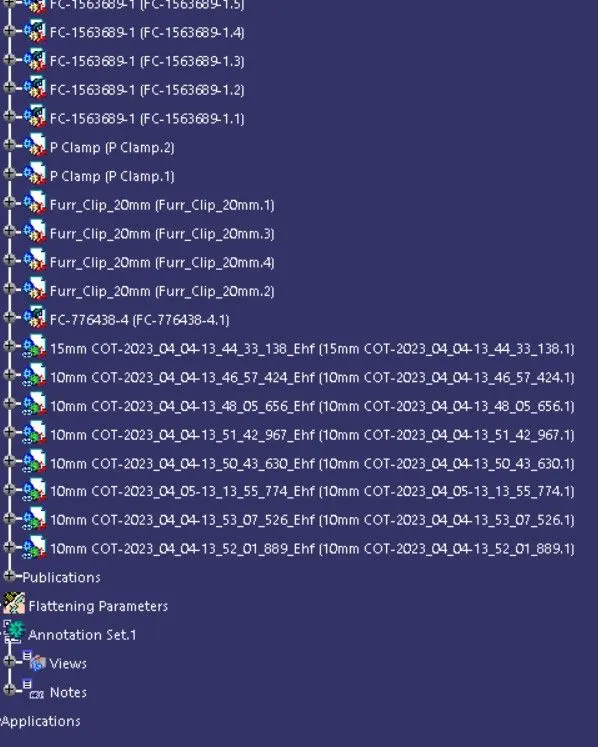
DESIGN TREE:
RESULT:
In this project i have successfully routed the wiring harness for the V16 Engine assembly and the flatten-view drawing was prepared in CATIA V5. Various packaging rules and constraints were considered while routing the harness. After finalizing the wire routing, we can request the corresponding Engine design team to provide additional holes for the mounting of Fir tree clips.