Project 1
1.
AIM: To design a battery pack for a car of roughly 150 kW with 120 V. To use 3500 mAh 3.6 V nominal NMC chemistry cell.
- To design the battery pack configuration.
- To draw the BMS topology for this battery pack.
THEORY:
A Battery Management System (BMS) is a technology dedicated to the oversight of a battery pack, which is an assembly of battery cells electrically organized in a row x column matrix configuration to enable the delivery of a targeted range of voltage and current for a duration of time against expected load scenarios.
The oversight that a BMS provides usually includes:
- Monitoring the battery
- Providing battery protection
- Estimating the battery's operational state
- Continually optimizing battery performance
- Reporting operational status to external devices
Here, the term “battery” implies the entire pack; however, the monitoring and control functions are specifically applied to individual cells, or groups of cells called modules in the overall battery pack assembly. Lithium-ion rechargeable cells have the highest energy density and are the standard choice for battery packs for many consumer products, from laptops to electric vehicles. While they perform superbly, they can be rather unforgiving if operated outside a generally tight safe operating area (SOA), with outcomes ranging from compromising the battery performance to outright dangerous consequences. The BMS certainly has a challenging job description, and its overall complexity and oversight outreach may span many disciplines such as electrical, digital, control, thermal, and hydraulic.
Battery management systems do not have a fixed or unique set of criteria that must be adopted. The technology design scope and implemented features generally correlate with:
- The costs, complexity, and size of the battery pack
- Application of the battery and any safety, lifespan, and warranty concerns
- Certification requirements from various government regulations where costs and penalties are paramount if inadequate functional safety measures are in place
There are many BMS design features, with battery pack protection management and capacity management being two essential features. We’ll discuss how these two features work here. Battery pack protection management has two key areas: electrical protection, which implies not allowing the battery to be damaged via usage outside its SOA, and thermal protection, which involves passive and/or active temperature control to maintain or bring the pack into its SOA.
Electrical Management Protection:
i. Current: Monitoring battery pack current and cell or module voltages is the road to electrical protection. The electrical SOA of any battery cell is bound by current and voltage. The below figure illustrates a typical lithium-ion cell SOA, and a well-designed BMS will protect the pack by preventing operation outside the manufacturer’s cell ratings. In many cases, further derating may be applied to reside within the SOA safe zone in the interest of promoting further battery lifespan.
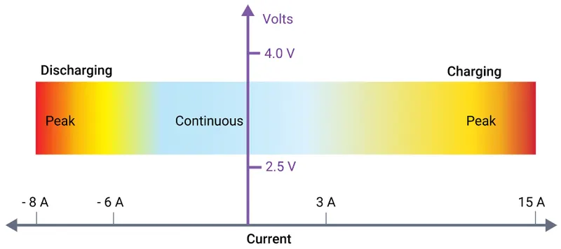
Lithium-ion cells have different current limits for charging than for discharging, and both modes can handle higher peak currents, albeit for short periods. Battery cell manufacturers usually specify maximum continuous charging and discharging current limits, along with peak charging and discharging current limits. A BMS providing current protection will certainly apply a maximum continuous current. However, this may be preceded to account for a sudden change of load conditions; for example, an electric vehicle’s abrupt acceleration. A BMS may incorporate peak current monitoring by integrating the current and after delta time, deciding to either reduce the available current or interrupt the pack current altogether. This allows the BMS to possess nearly instantaneous sensitivity to extreme current peaks, such as a short-circuit condition that has not caught the attention of any resident fuses, but also be forgiving to high peak demands, as long as they are not excessive for too long.
ii. Voltage: A lithium-ion cell must operate within a certain voltage range. These SOA boundaries will ultimately be determined by the intrinsic chemistry of the selected lithium-ion cell and the temperature of the cells at any given time. Moreover, since any battery pack experiences a significant amount of current cycling, discharging due to load demands and charging from a variety of energy sources, these SOA voltage limits are usually further constrained to optimize battery lifespan. The BMS must know what these limits are and will command decisions based on the proximity to these thresholds. For example, when approaching the high voltage limit, a BMS may request a gradual reduction of the charging current or may request the charging current be terminated altogether if the limit is reached. However, this limit is usually accompanied by additional intrinsic voltage hysteresis considerations to prevent control chatter about the shutdown threshold. On the other hand, when approaching the low voltage limit, a BMS will request that key active offending loads reduce their current demands. In the case of an electric vehicle, this may be carried out by reducing the allowed torque available to the traction motor. Of course, the BMS must make safety considerations for the driver the highest priority while protecting the battery pack to prevent permanent damage.
iii. Temperature: At face value, lithium-ion cells may have a wide temperature operating range, but overall battery capacity diminishes at low temperatures because chemical reaction rates slow down remarkably. With respect to capability at low temperatures, they do perform much better than lead-acid or NiMh batteries; however, temperature management is prudently essential since charging below 0°C (32°F) is physically problematic. The phenomenon of plating of metallic lithium can occur on the anode during sub-freezing charging. This is permanent damage and not only results in a reduced capacity, but cells are more vulnerable to failure if subjected to vibration or other stressful conditions. A BMS can control the temperature of the battery pack through heating and cooling.
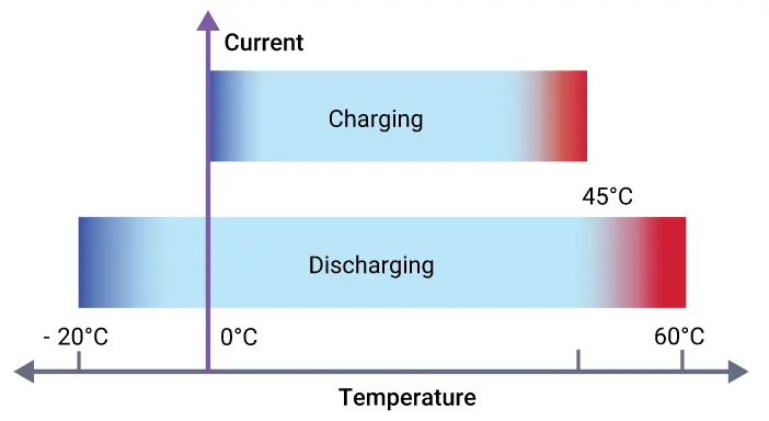
Realized thermal management is entirely dependent upon the size and cost of the battery pack and performance objectives, design criteria of the BMS, and product unit, which may include consideration of targeted geographic region (e.g. Alaska versus Hawaii). Regardless of the heater type, it is generally more effective to draw energy from an external AC power source, or an alternative resident battery purposed to operate the heater when needed. However, if the electric heater has a modest current draw, energy from the primary battery pack can be siphoned to heat itself. If a thermal-hydraulic system is implemented, then an electric heater is used to heat the coolant which is pumped and distributed throughout the pack assembly.
BMS design engineers undoubtedly have tricks of their design trade to trickle heat energy into the pack. For example, various power electronics inside the BMS dedicated to capacity management can be turned on. While not as efficient as direct heating, it can be leveraged regardless. Cooling is particularly vital to minimize the performance loss of a lithium-ion battery pack. For example, perhaps a given battery operates optimally at 20°C; if the pack temperature increases to 30°C, its performance efficiency could be reduced by as much as 20%. If the pack is continuously charged and recharged at 45°C (113°F), the performance loss can rise to a hefty 50%. Battery life can also suffer from premature ageing and degradation if continually exposed to excessive heat generation, particularly during fast charging and discharging cycles. Cooling is usually achieved by two methods, passive or active, and both techniques may be employed. Passive cooling relies on the movement of airflow to cool the battery. In the case of an electric vehicle, this implies that it is simply moving down the road. However, it may be more sophisticated than it appears, as airspeed sensors could be integrated to strategically auto-adjust deflective air dams to maximize airflow. Implementation of an active temperature-controlled fan can help at low speeds or when the vehicle has stopped, but all this can do is merely equalize the pack with the surrounding ambient temperature. In the event of a scorching hot day, this could increase the initial pack temperature. Thermal hydraulic active cooling can be designed as a complementary system and typically utilizes ethylene-glycol coolant with a specified mixture ratio, circulated via an electric motor-driven pump through pipes/hoses, distribution manifolds, a cross-flow heat exchanger (radiator), and cooling plate resident against the battery pack assembly. A BMS monitors the temperatures across the pack and opens and closes various valves to maintain the temperature of the overall battery within a narrow temperature range to ensure optimal battery performance.
Capacity Management
Maximizing a battery pack capacity is arguably one of the most vital battery performance features that a BMS provides. If this maintenance is not performed, a battery pack may eventually render itself useless. The root of the issue is that a battery pack “stack” (series array of cells) is not perfectly equal and intrinsically has slightly different leakage or self-discharge rates. Leakage is not a manufacturer defect but a battery chemistry characteristic, though it may be statistically impacted by minute manufacturing process variations. Initially, a battery pack may have well-matched cells, but over time, the cell-to-cell similarity further degrades, not just due to self-discharge, but also impacted by charge/discharge cycling, elevated temperature, and general calendar ageing. With that understood, recall earlier the discussion that lithium-ion cells perform superbly, but can be rather unforgiving if operated outside a tight SOA. We learned previously about required electrical protection because lithium-ion cells do not deal well with over-charging. Once fully charged, they cannot accept any more current, and any additional energy pushed into it gets transmuted in heat, with voltage potentially rising quickly, possibly to dangerous levels. It is not a healthy situation for the cell and can cause permanent damage and unsafe operating conditions if it continues.
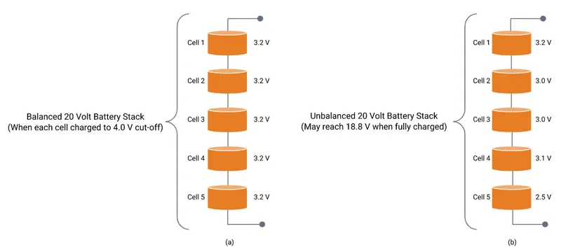
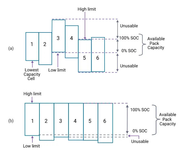
The battery pack series cell array is what determines the overall pack voltage, and the mismatch between adjacent cells creates a dilemma when attempting to charge up any stack. The below figure shows why this is so. If one has a perfectly balanced set of cells, all is fine as each will charge up in an equal fashion, and the charging current can be cut off when the upper 4.0 voltage cut-off threshold is reached. However, in the unbalanced scenario, the top cell will reach its charge limit early, and the charging current needs to be terminated for the leg before other underlying cells have been charged to full capacity.
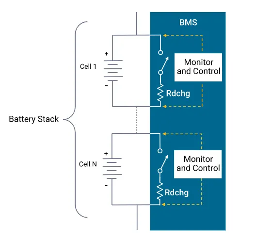
The BMS is what steps in and saves the day or the battery pack in this case. To show how this works, a key definition needs to be explained. The state-of-charge (SOC) of a cell or module at a given time is proportional to the charge available relative to the total charge when fully charged. Thus, a battery that resides at 50% SOC implies it is 50% charged, which is akin to a fuel gauge figure of merit. BMS capacity management is all about balancing the variation of the SOC across each stack in the pack assembly. Since the SOC is not a directly measurable quantity, it can be estimated by various techniques, and the balancing scheme itself generally falls into two main categories, passive and active. There are many variations of themes, and each type has pros and cons. It’s up to the BMS design engineer to decide which is optimal for the given battery pack and its application. Passive balancing is the easiest to implement, as well as to explain the general balancing concept. The passive method allows every cell in the stack to have the same charged capacity as the weakest cell. Using a relatively low current, it shuttles a small amount of energy from high SOC cells during the charging cycle so that all cells charge to their maximum SOC. The below figure illustrates how this is accomplished by the BMS. It monitors each cell and leverages a transistor switch and an appropriately sized discharge resistor in parallel with each cell. When the BMS senses a given cell is approaching its charge limit, it will steer excess current around it to the next cell below in a top-down fashion.
The balancing process endpoints, before and after, are shown in the figure below. In summary, a BMS balances a battery stack by allowing a cell or module in a stack to see a different charging current than the pack current in one of the following ways:
- Removal of charge from the most charged cells, which gives headroom for additional charging current to prevent overcharging, and allows the less charged cells to receive more charging current.
- Redirection of some or nearly all of the charging current around the most charged cells, thereby allowing the less charged cells to receive charging current for a longer length of time.
Types of battery management systems
Battery management systems range from simple to complex and can embrace a wide range of different technologies to achieve their prime directive to “take care of the battery.” However, these systems can be categorized based on their topology, which relates to how they are installed and operate upon the cells or modules across the battery pack.
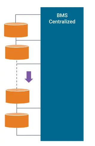
i. Centralized BMS Architecture
It has one central BMS in the battery pack assembly. All the battery packages are connected to the central BMS directly. The structure of a centralized BMS is shown in the figure below. The centralized BMS has some advantages. It is more compact, and it tends to be the most economical since there is only one BMS. However, there are disadvantages to a centralized BMS. Since all the batteries are connected to the BMS directly, the BMS needs a lot of ports to connect with all the battery packages. This translates to lots of wires, cabling, connectors, etc. in large battery packs, which complicates both troubleshooting and maintenance.
ii. Modular BMS Topology
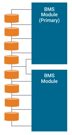
Similar to a centralized implementation, the BMS is divided into several duplicated modules, each with a dedicated bundle of wires and connections to an adjacent assigned portion of a battery stack. In some cases, these BMS submodules may reside under a primary BMS module oversight whose function is to monitor the status of the submodules and communicate with peripheral equipment. Thanks to the duplicated modularity, troubleshooting and maintenance are easier, and extension to larger battery packs is straightforward. The downside is overall costs are slightly higher, and there may be duplicated unused functionality depending on the application.
iii. Primary/Subordinate BMS
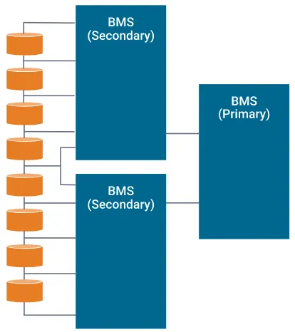
Conceptually similar to the modular topology, however, in this case, the slaves are more restricted to just relaying measurement information, and the master is dedicated to computation and control, as well as external communication. So, like the modular types, the costs may be lower since the functionality of the slaves tends to be simpler, with likely less overhead and fewer unused features.
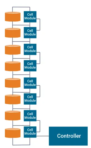
iv. Distributed BMS Architecture
Considerably different from the other topologies, where the electronic hardware and software are encapsulated in modules that interface to the cells via bundles of attached wiring. A distributed BMS incorporates all the electronic hardware on a control board placed directly on the cell or module that is being monitored. This alleviates the bulk of the cabling to a few sensor wires and communication wires between adjacent BMS modules. Consequently, each BMS is more self-contained and handles computations and communications as required. However, despite this apparent simplicity, this integrated form does make troubleshooting and maintenance potentially problematic, as it resides deep inside a shield module assembly. Costs also tend to be higher as there are more BMSs in the overall battery pack structure.
Importance of battery management systems
Functional safety is of the highest importance in a BMS. It is critical during charging and discharging operations, to prevent the voltage, current, and temperature of any cell or module under supervisory control from exceeding defined SOA limits. If limits are exceeded for a length of time, not only is a potentially expensive battery pack compromised, but dangerous thermal runaway conditions could ensue. Moreover, lower voltage threshold limits are also rigorously monitored for the protection of the lithium-ion cells and functional safety. If the Li-ion battery stays in this low-voltage state, copper dendrites could eventually grow on the anode, which can result in elevated self-discharge rates and raise possible safety concerns. The high energy density of lithium-ion powered systems comes at a price that leaves little room for battery management error. Thanks to BMSs, and lithium-ion improvements, this is one of the most successful and safe battery chemistries available today.
The performance of the battery pack is the next highest important feature of a BMS, and this involves electrical and thermal management. To electrically optimize the overall battery capacity, all the cells in the pack are required to be balanced, which implies that the SOC of adjacent cells throughout the assembly are approximately equivalent. This is exceptionally important because not only can optimal battery capacity be realized, but it helps prevent general degradation and reduces potential hotspots from overcharging weak cells. Lithium-ion batteries should avoid discharge below low voltage limits, as this can result in memory effects and significant capacity loss. Electrochemical processes are highly susceptible to temperature, and batteries are no exception. When environmental temperature drops, capacity and available battery energy roll off significantly. Consequently, a BMS may engage an external in-line heater that resides on, say, the liquid cooling system of an electric vehicle battery pack, or turn on resident heater plates that are installed underneath modules of a pack incorporated within a helicopter or other aircraft. Additionally, since charging frigid lithium-ion cells is detrimental to battery life performance, it is important to first elevate the battery temperature sufficiently. Most lithium-ion cells cannot be fast-charged when they are less than 5°C and should not be charged at all when they are below 0°C. For optimum performance during typical operational usage, BMS thermal management often ensures that a battery operates within a narrow Goldilocks region of operation (e.g. 30 – 35°C). This safeguards performance, promotes longer life, and fosters a healthy, reliable battery pack.
Benefits of battery management systems
An entire battery energy storage system, often referred to as BESS could be made up of tens, hundreds, or even thousands of lithium-ion cells strategically packed together, depending on the application. These systems may have a voltage rating of less than 100V but could be as high as 800V, with pack supply currents ranging as high as 300A or more. Any mismanagement of a high-voltage pack could trigger a life-threatening, catastrophic disaster. Consequently, therefore BMSs are critical to ensure safe operation. The benefits of BMSs can be summarized as follows.
- Functional Safety. Hands down, for large-format lithium-ion battery packs, this is particularly prudent and essential. But even smaller formats used in, say, laptops, have been known to catch fire and cause enormous damage. The personal safety of users of products that incorporate lithium-ion powered systems leaves little room for battery management error.
- Life Span and Reliability. Battery pack protection management, electrical and thermal, ensures that all the cells are used within declared SOA requirements. This delicate oversight ensures the cells are taken care of against aggressive usage and fast charging and discharging cycling, and inevitably results in a stable system that will potentially provide many years of reliable service.
- Performance and Range. BMS battery pack capacity management, where cell-to-cell balancing is employed to equalize the SOC of adjacent cells across the pack assembly, allows optimum battery capacity to be realized. Without this BMS feature to account for variations in self-discharge, charge/discharge cycling, temperature effects, and general ageing, a battery pack could eventually render itself useless.
- Diagnostics, Data Collection, and External Communication. Oversight tasks include continuous monitoring of all battery cells, where data logging can be used by itself for diagnostics, but is often purposed to the task for computation to estimate the SOC of all cells in the assembly. This information is leveraged for balancing algorithms but collectively can be relayed to external devices and displays to indicate the resident energy available, estimate expected range or range/lifetime based on current usage, and provide the state of health of the battery pack.
- Cost and Warranty Reduction. The introduction of a BMS into a BESS adds costs and battery packs are expensive and potentially hazardous. The more complicated the system, the higher the safety requirements, resulting in the need for more BMS oversight presence. But the protection and preventive maintenance of a BMS regarding functional safety, lifespan and reliability, performance and range, diagnostics, etc. guarantees that it will drive down overall costs, including those related to the warranty.
a. Calculation
Car Specifications:
Rated Power Rating = 150 kW
Rated Voltage = 120 V
Battery Specifications:
Nominal Capacity = 3.5 Ah
Nominal Voltage = 3.6 V
No. of cells in series = 120/3.6 = 33.33
Rounding off the cells in series
Case 1: Rounding off 33.33 to 33
Nominal Battery Voltage = 3.6 x 33 = 118.8 V
Case 2: Rounding off 33.33 to 34
Nominal Battery Voltage = 3.6 x 34 = 122.4 V
It's always better to have more voltage. So, we can pick 34 cells in series.
No. of cells in parallel = Rated Current/Cell Nominal Capacity
Rated current = 150 kW/120 V = 1250 A
No. of cells in parallel = 1250/3.5 = 357. 14
Rounding off the cells in parallel
Case 1: Rounding off 357.14 to 357
Nominal battery current = 3.5 x 357 = 1249.5 Ah
Case 2: Rounding off 357.14 to 358
Nominal battery current = 3.5 x 358 = 1253 Ah
It's always recommended to discharge the battery for continuous current in 1C. Hence, we will choose 358 cells in parallel.
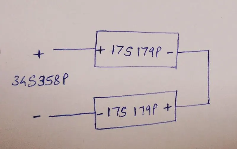
Hence, the battery pack configuration is 34S358P.
Total cells = 34 x 358 = 12172
Conclusion:
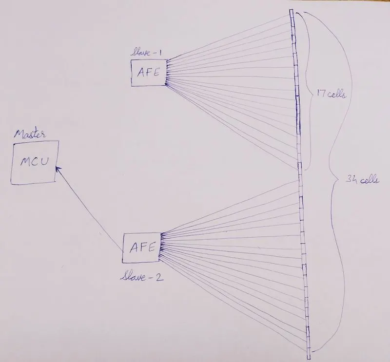
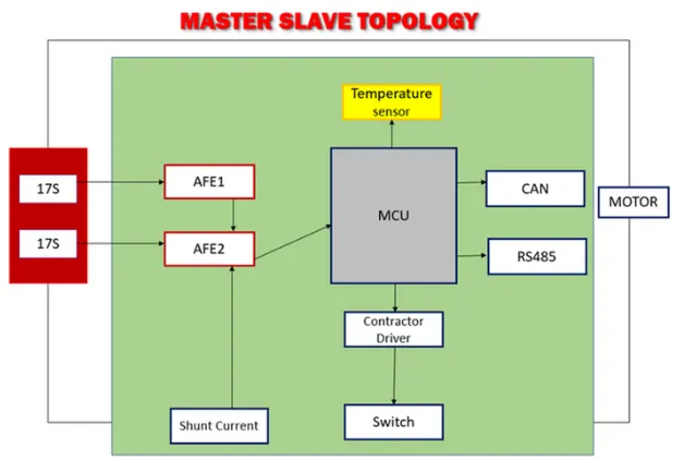
b. The BMS topology for this battery pack would be Master-Slave Topology because the battery pack consists of more than 18 cells in series.
In the below figure, the Master-Slave Topology consists of 2 slaves (AFEs).
Slave 1 consists of 17 cells in series.
Slave 2 consists of 17 cells in series.
Conclusion: Hence, the battery pack configuration is designed and the BMS topology is drawn.
2.
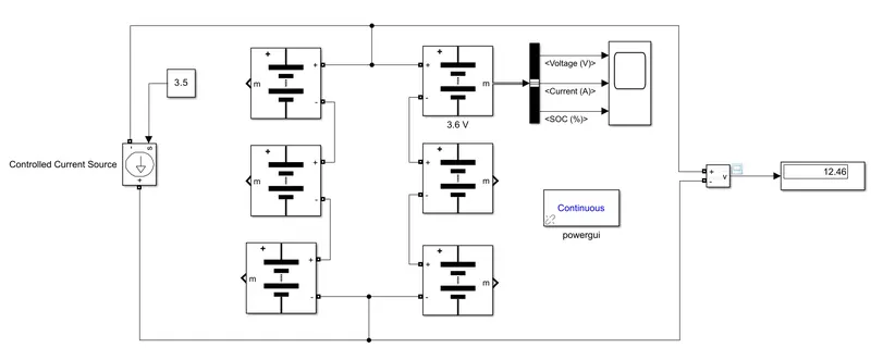
AIM: To build a 3S2P battery pack configuration with a generic battery block using MATLAB/Simulink.
SIMULINK MODEL:
CALCULATION:
Total number of cells in battery pack = 3 x 2 = 6
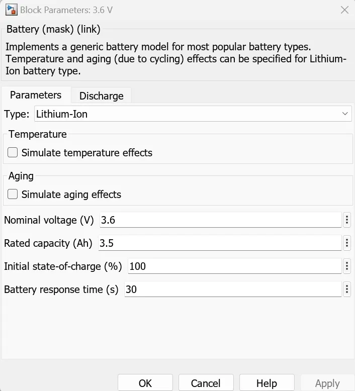
Nominal voltage of cell = 3.6 V
Nominal capacity = 3.5 Ah
Nominal voltage of battery pack = no. of cells in series x nominal voltage of the cell
= 3 x 3.6 = 10.8 V
Rated capacity of battery pack = no. of cells in parallel x rated capacity of the cell
= 2 x 3.5 = 7 Ah
Overall voltage of the battery pack = maximum capacity of the cell x no. of cells in series
= 4.2 x 3 = 12.6 V
RESULT:
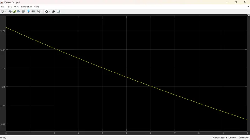
The voltage is dropped from 12.57 V to 12.46 V for this battery pack.
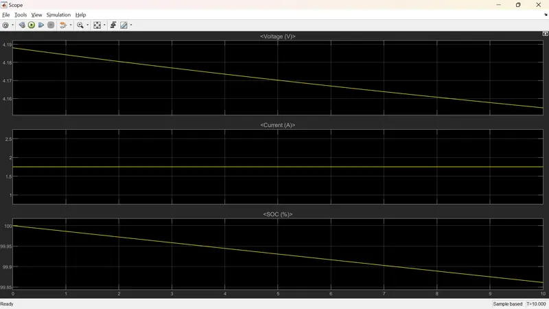
The first plot shows the SOC of the cell. It dropped from 100% to 99.86%.
The second plot shows the current of the cell. It is nearly 1.8 A.
The third plot shows the voltage of the cell. It dropped from approx. 4.19 V to 4.155 V.
CONCLUSION:
Hence, the 3S2P battery pack configuration is built with the generic battery block using MATLAB/Simulink.