Project 1
Report on wire harness design on the given engine and flattening of wire harness.
Aim: To perform the wire harness routing on the engine by electrically defing each required component and using flatten workbench to flatten the the wire harness.
Given engine design:
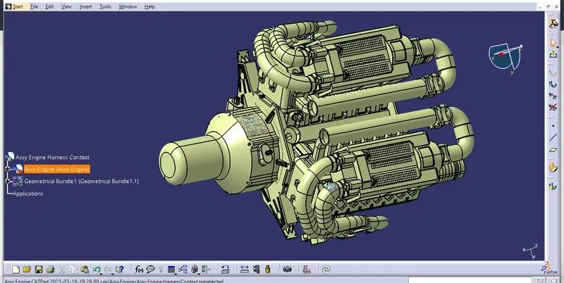
Step 1: After downloading the given CAD data for engine we open each file in the catia, make a new product file and add the engine cad file into that product file and change the name of product file into assy engine harness context.
- Now after observing the engine file completly we found out that we need (8 + 2)*2= 20 four pole connector. 16 for injector connector sensor (8 on each side).
- One two pole connector, for temprature sensor.
- Two three pole connector sensor one for gm cam sensor and one for coolant temprature sesor.
- So based on these factor our connector which is choosen for routing are as shown below:
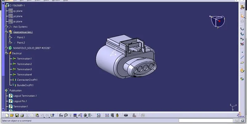
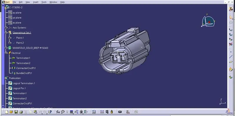
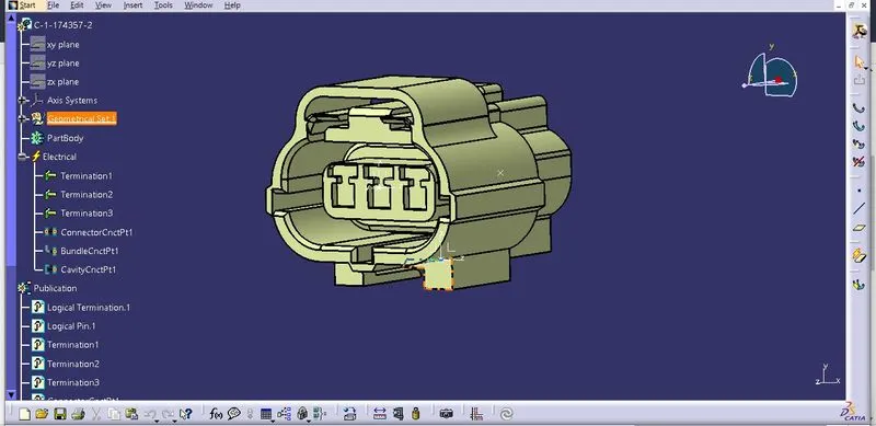
- Above connectors are first electrically defind in the electrical part design workbench through the geometrical parmeters and defining the bindle connection point and connector connection point in the each connector.
Step 2 : Now place each connector at the desired location in assembly of engine as shown:
- Use the mechanical design assembly workbench to place the each connector at the positions shown below by using the command manipulation, snap geometry and compass movement.
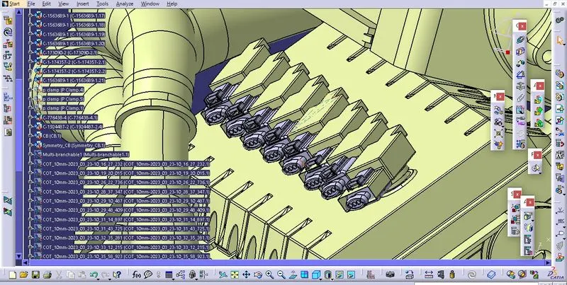
- Four poles connector are placed at the injector sensors as shown below:
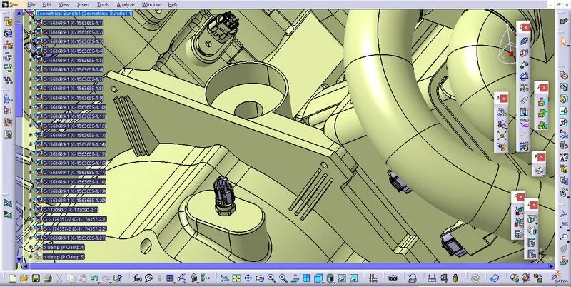
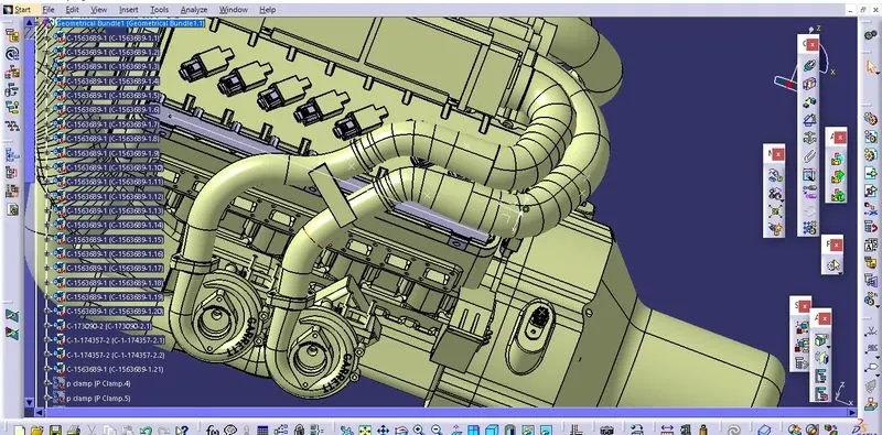
- Two pole and three poles connectors are placed gm cam sensor and coolant temp. sensor as shown below:
Step 3: Now place the interconnection connector at the right side engine this is the manin connector from where routing begins, we are assuming that the chasis interconnection is from the right side of engine so we have taken the interconnection connector on right side.
- Electrically define the interconnection connector by drawing the geometrical parameters first such as connection connector point, bundle connection point and axis system and cavity connection point.
- Now connect the clip electrically (after defing it) to the interconnection connector which would help it to park sucessfully.
- Now align the L clip on rightmost side screw hole and now park the interconnection connector with the clip over it as shown below:
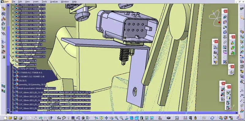
- First define the P clamp elctrically then place the p clamp aligning with screw holes in the engine as shown below:
- For defining the p clamp we take 3 reference plane and two reference point then using the define electrical support in the electrical workbench.
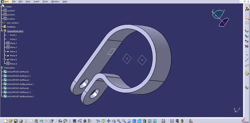
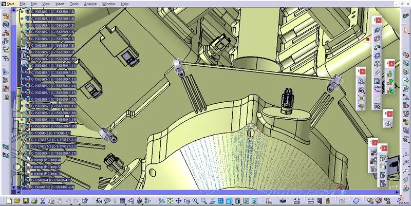
Step 5 : Define the guiding channels electrically by defining each exit point from the small chanells as bundle connection point and the entry point of guiding channel as bundle connection point as shown below:
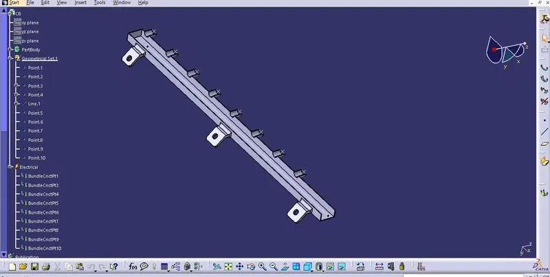
- Now take symmetry of this channel to create the other side guiding channel and define it electrically same as we did in previous channel
- Then place the guiding channels near injection sensor connectors on each side as shown below:
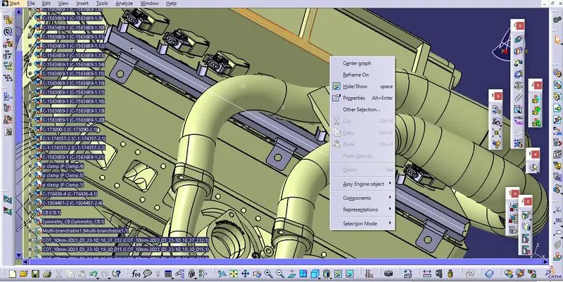
Step 6: After placing the clips, clamps and mounting now start routing starting from the interconnection connector.
- Routing we took branch length to be minimum 50 mm.
- Gave the external reference curve to the branch coming out of p clamp to connect further, took the diameter of main harness to be 15 mm.
- Gave the branch point in the middle of bundle segment to make the harness branches of 5 mm going toward the connector placed near to branch point.
- The branches which are going to guiding channels taken to be of 10 mm amd same dia for the branch placed inside the channel.
- Now make the branch points 65mm apart in the guiding channels branch and route the harness branches of 5mm going towards the each connector placed at the injection sensor, same we do in the other channel.
- We are using these giding channels to protect the wire harness inside these channels from excessive heat from the exaust outlet.
- So finally the routing will look like this:
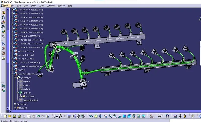
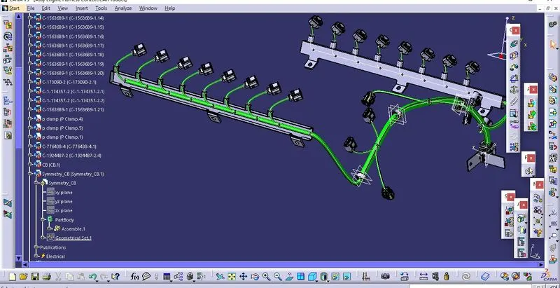
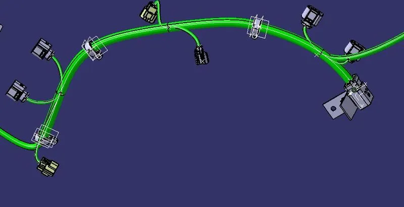
- On checking the bundle continuity we get the result as shown below:
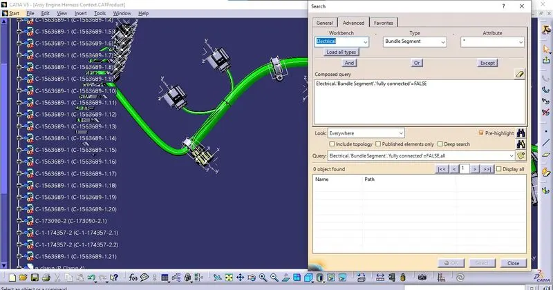 , which means that the bundle is continuous.
Step 7: Add the protective covering onto the branches to provide the protection from heat.
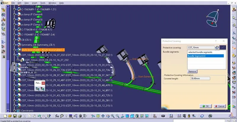
- So we added the corroguted tubes on the branches, such that diameter of corroguted tubes is selcted more than diameter of respective branch, for ex. as shown below:
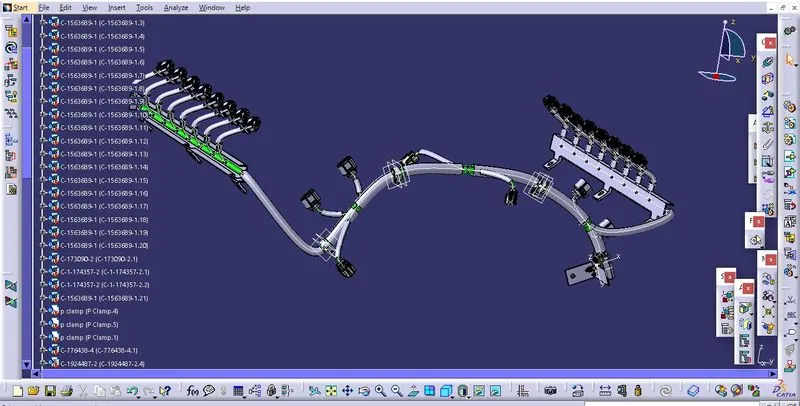
- So wire harness with protective covering will look like this:
Step 8:Now create a new product file open it in elctrical harness flattenning workbench, then define the flattening parametrs as shown below:
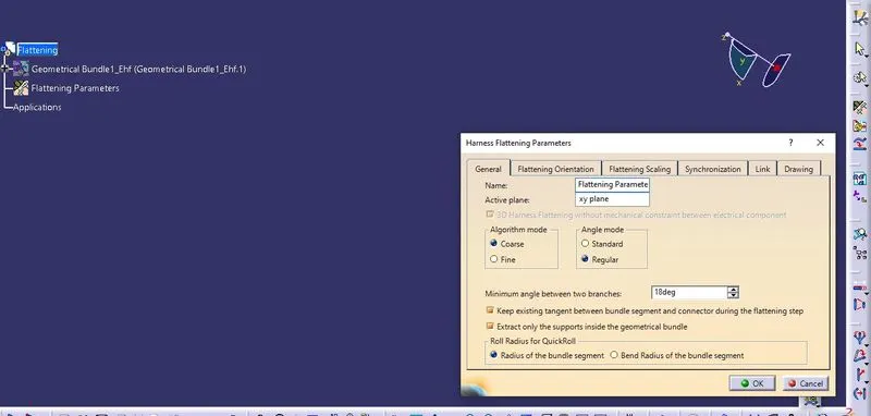
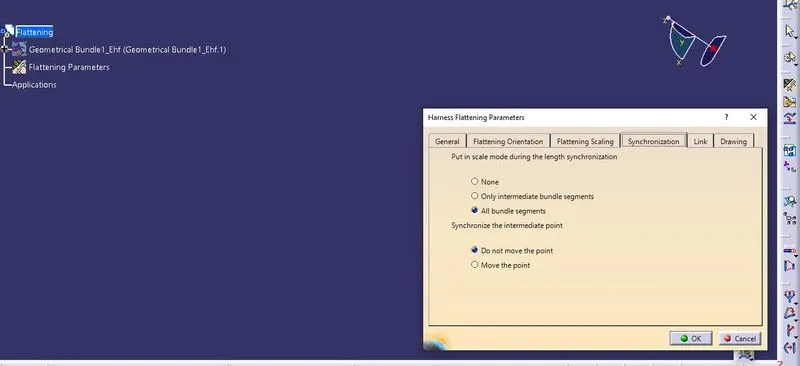
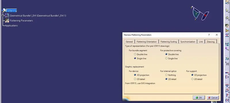 , then click ok to set the parametrs.
- Now extract the geometrical bundle from the main assembly wire harness of engine product file by using the command extract in the electrical flattening workbench, and use the command such as quick roll and rotate to align the whole harness in one plane as shown below:
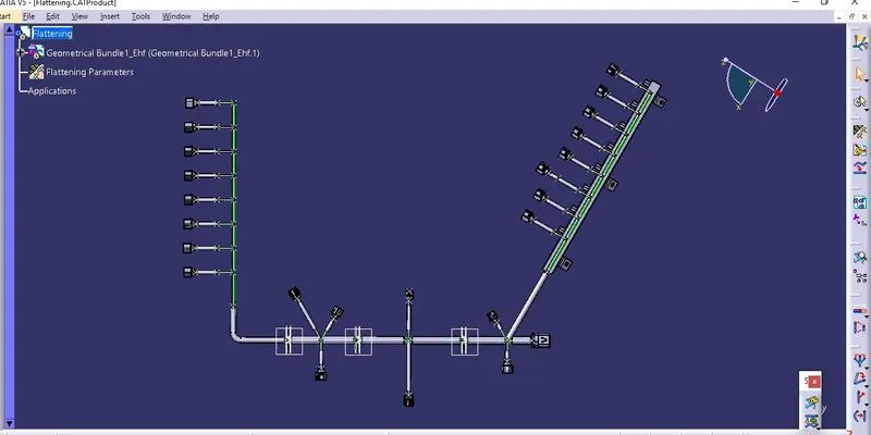
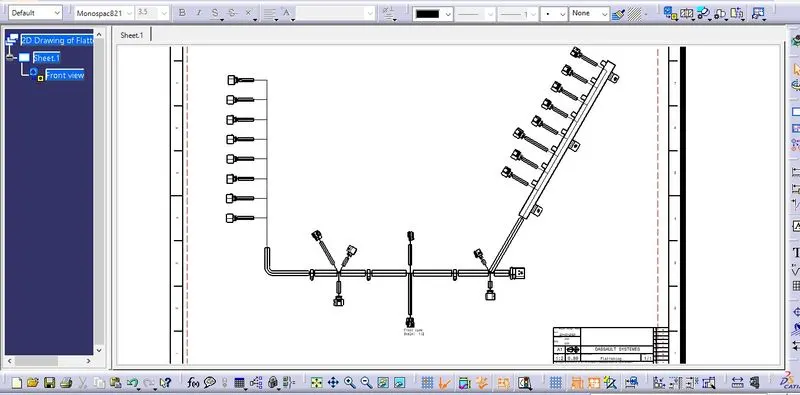
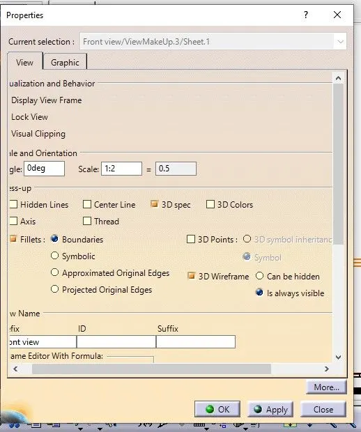
Step 9: Create a drawing file select the size of A1 in iso standards then take the front view of model present in the flattening workbench, change the settings of front view to turn the 3d wireframe on and check it to always visible as shown below:
- Give the background to sheet in edit background option and select the title and frame for the sheet so our final 2D drawing sheet will look like this: