Project 1
Project 1
AIM
To create harness for enging assy, with proper routing and protection.
Engine wiring harness: is an organized set of wires, cables, connectors and terminals that controls a vehicle’s electrical system. Engine wire harnesses relay electrical power and control information to outlying components such as:
- Alternators
- Audio Systems
- Batteries
- Blower Motors
- Computers
- Fuel Injectors
- Fuses
- Windshield Wipers
- And everything else that is controlled electrically that you can find in a vehicle
OEMs look for wire and cable harnesses that can withstand vibrations, abrasions, dust and high moisture settings. Constricted wires in a non-flexible bundle help decrease electrical shorts in an engine wire harness. Flame retardant overmolding lowers the risks of electrical fires and keeps moisture out of the wire and cables, preventing corrosion. Adhering the wire harness to the chassis of a vehicle helps prevent vibration and cable abrasions from vehicle movement.
2013/14 GT500 Engine and Transmission & Underhood Wiring Harness Drawings
Procedure:
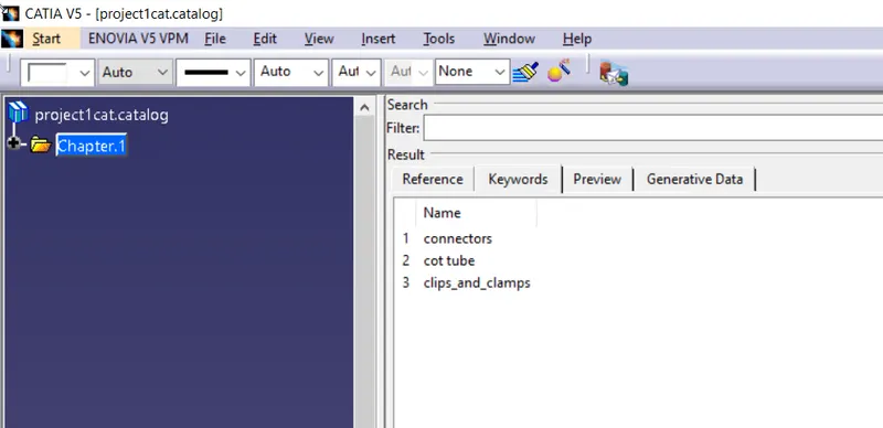
firstly create a catalog That contains connectors, protection tube, supports
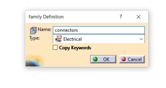
This will be nessory , and can reduce the work while assymbly
Connector1 Peperation:
12-pin connector - C-776438-4
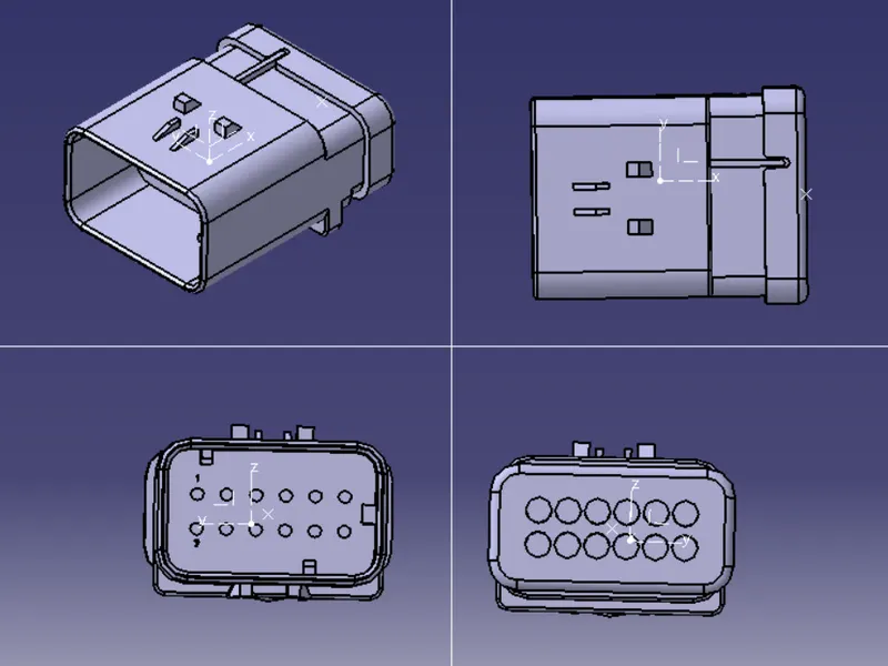
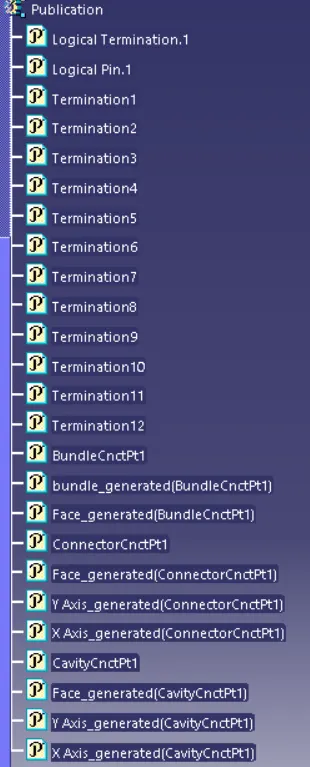
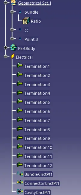
Create nessory points for bundle entry, connector connection and axis system
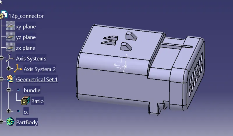
Now define as connector
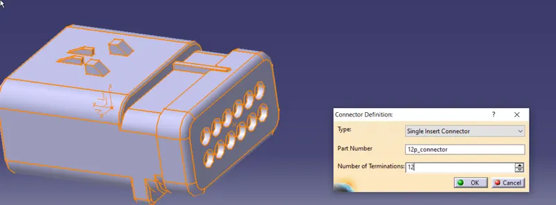
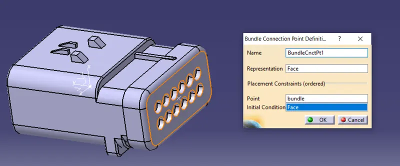
Define Bundle entry point
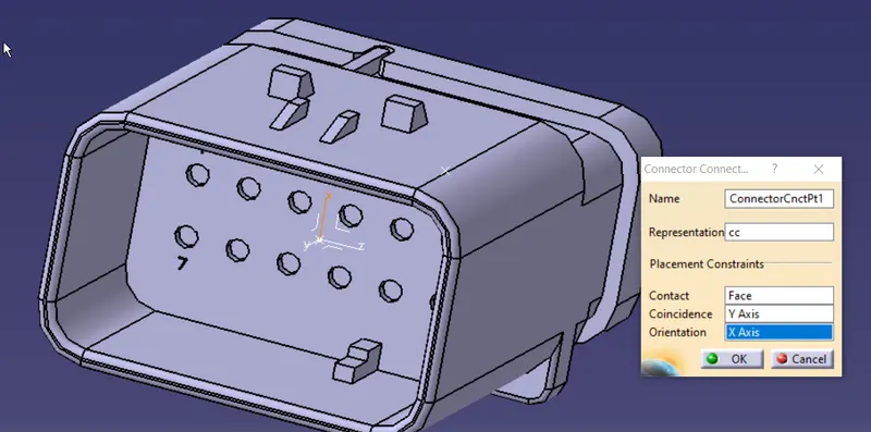
Define connector connection point
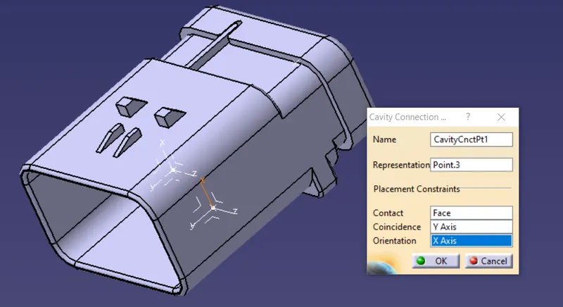
Add cavity point
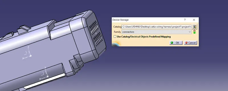
save and add to catalog under connector
Connector2 preperation
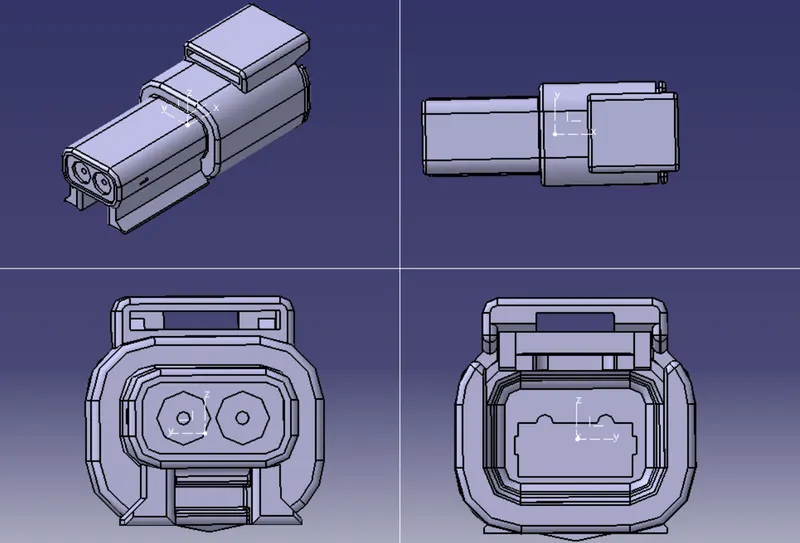
Create nessory points for bundle entry, connector connection and axis system
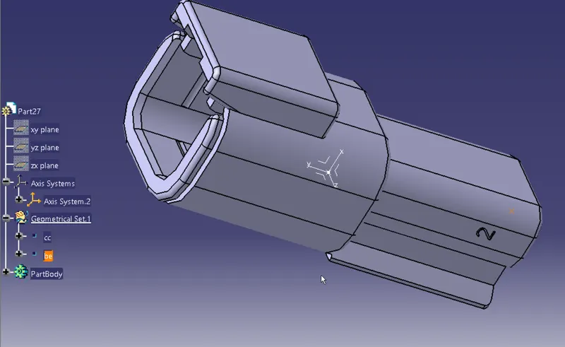
Define as connector
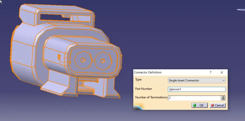
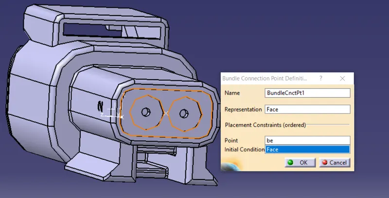
Define bundle entry point
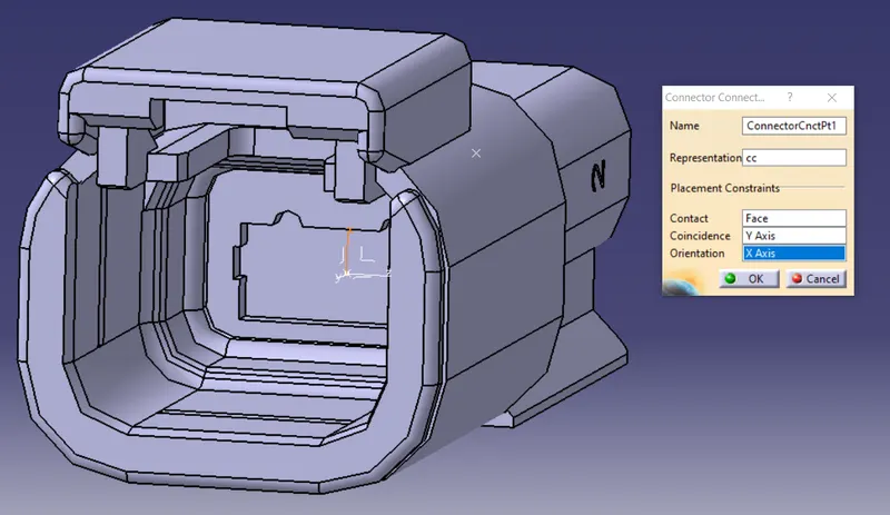
Define connector connection point
save and add to catalog under connector
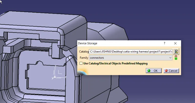
Connector3 preperarions
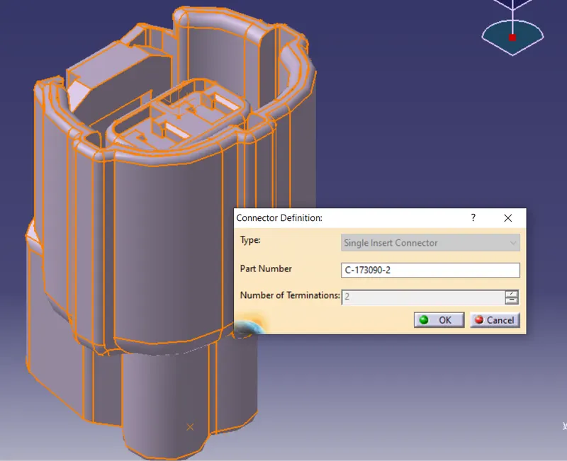
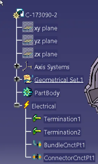
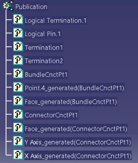
C-173090-2
create nessory bundle and cocnnector connection point
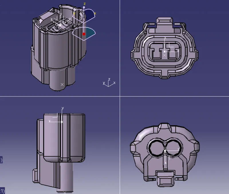
define as connector
define bundle entry point
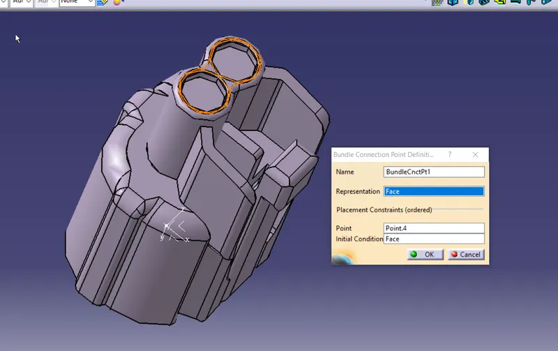
define conector connection
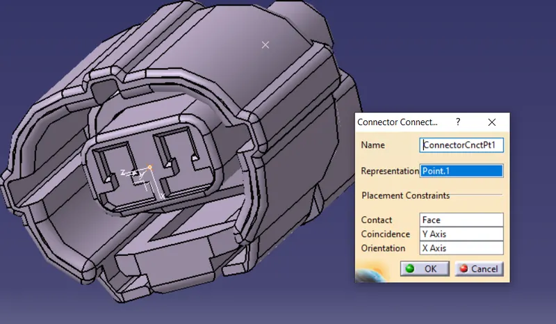
save and add to family
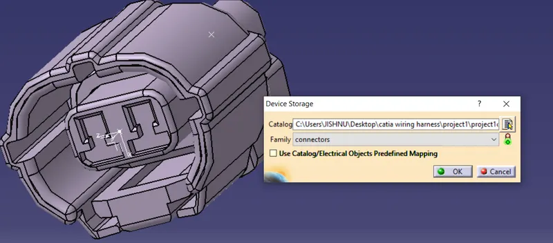
Connector4 preperationns
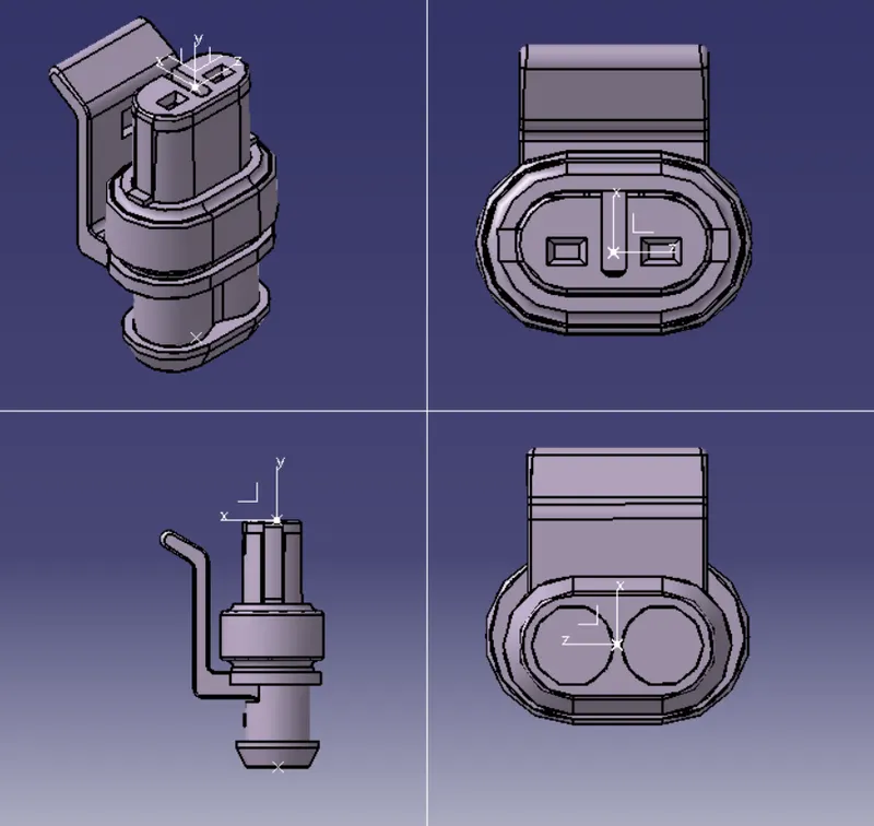
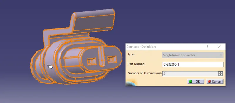
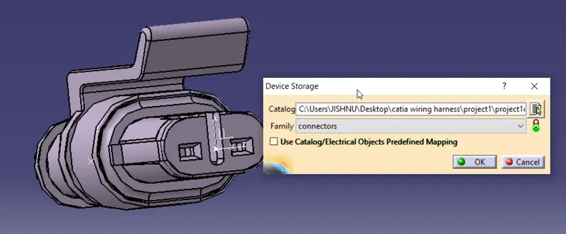
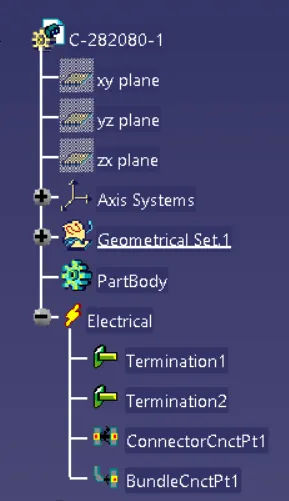
C-282080-1
Create nessory bundle and cocnnector connection point
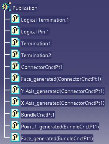
Define as connector
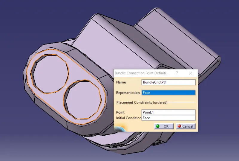
Define bundle entry point
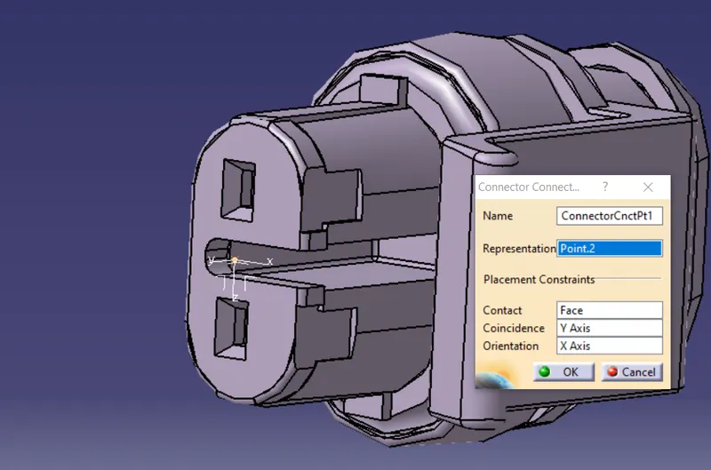
Define conector connection
Save and add to family
Connector5 preperations
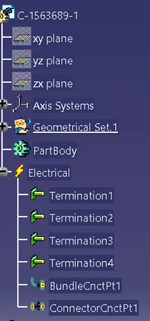
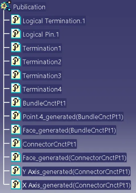
C-1563689-1
Create nessory bundle and connector connection point
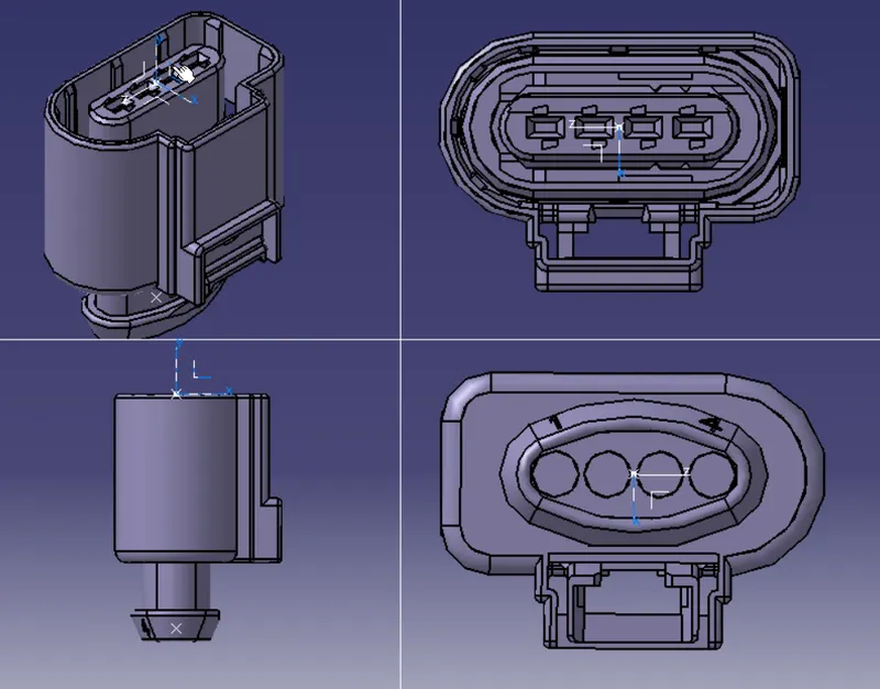
Define as connector
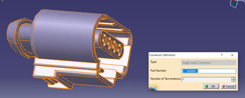
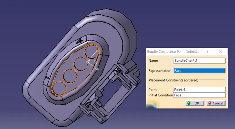
Define bundle entry point
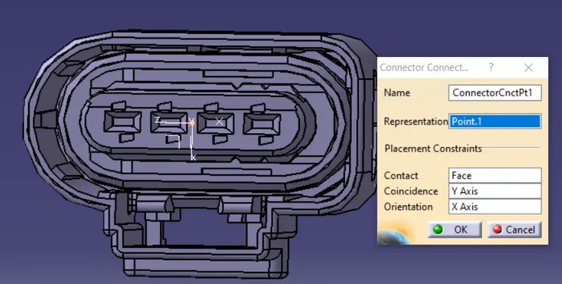
Define conector connection
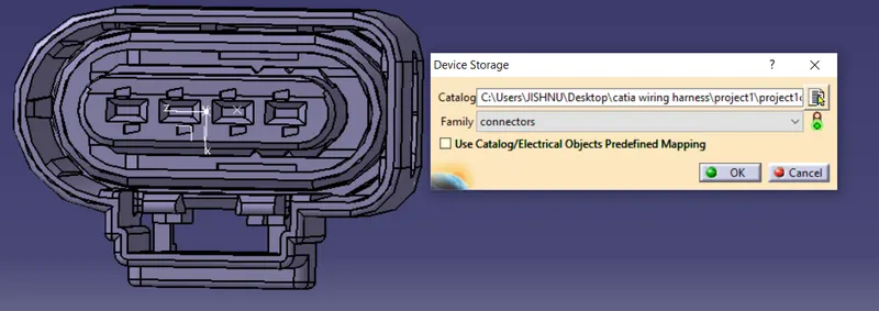
Save and add to family
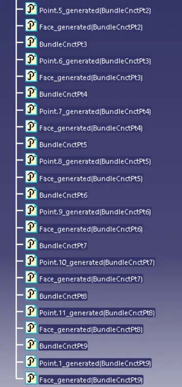
Bundle channel
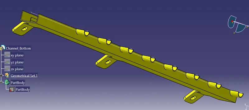
Left channel:
Create nessory bundle connection point
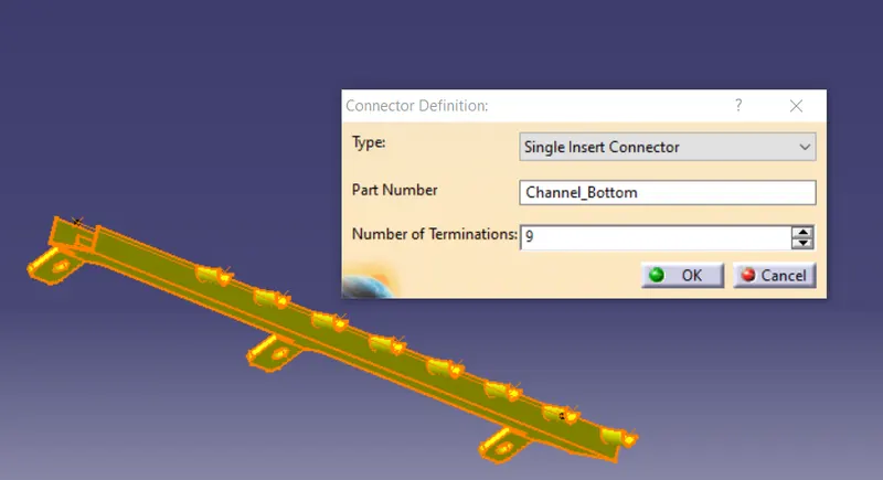
Define as connector
Define bundle entry points
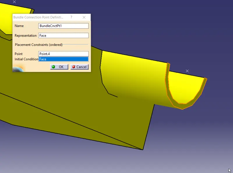
also create a semitry for right side and do the same to create
Right chanel
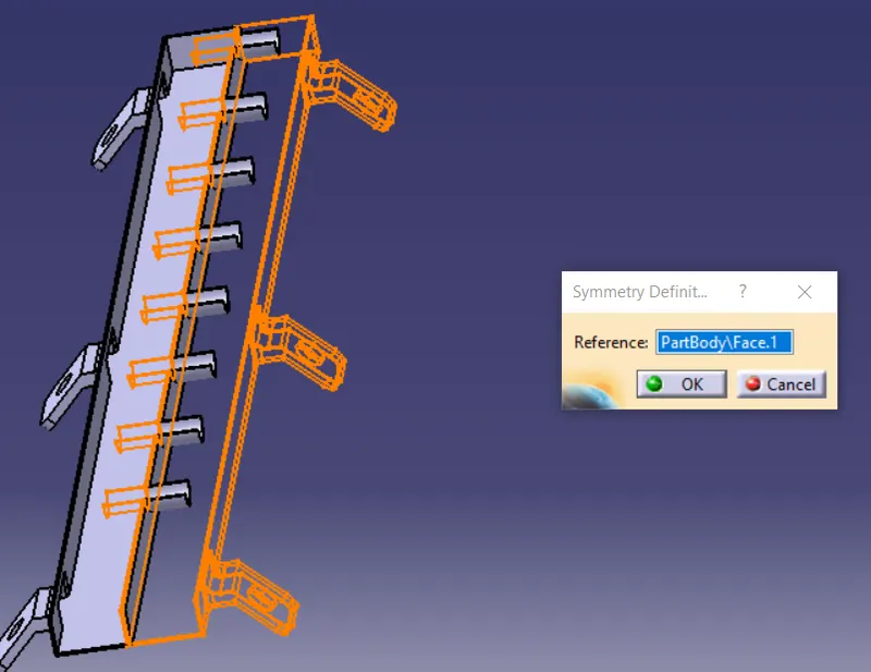
save and add to family
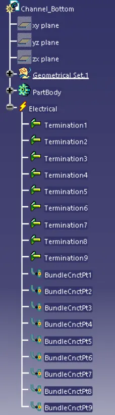
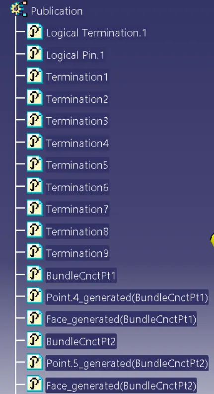
Wiring harness assymbly:
Create a new product file to assymble the parts
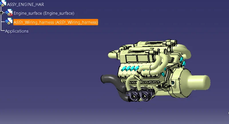
Convert ASSy_wiring haernes product to Geometrical bundle
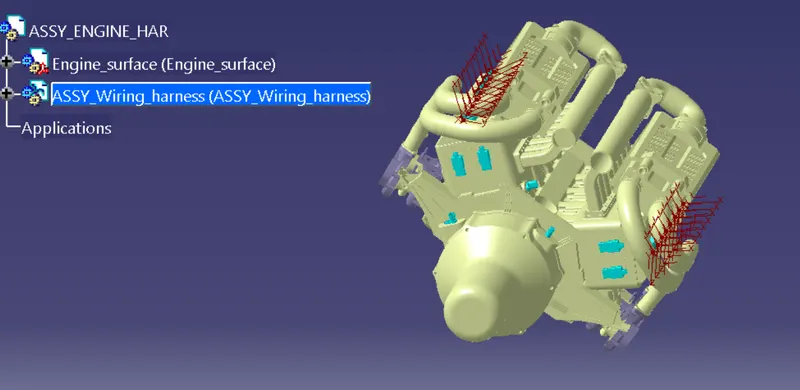
Now add parts from catalog created earlier
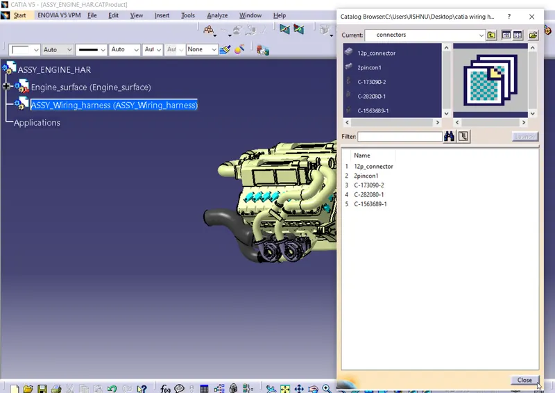
Start placeing connetors to respective place as shown use snap and move in combination, also make sure not to create any links with the given engine structure.
lets start adding injector connectors;
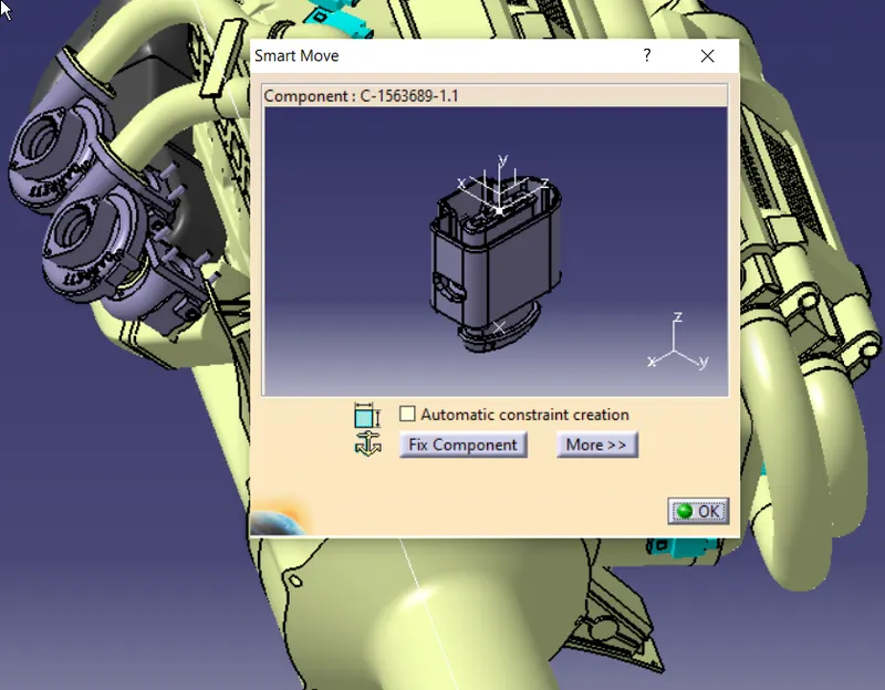
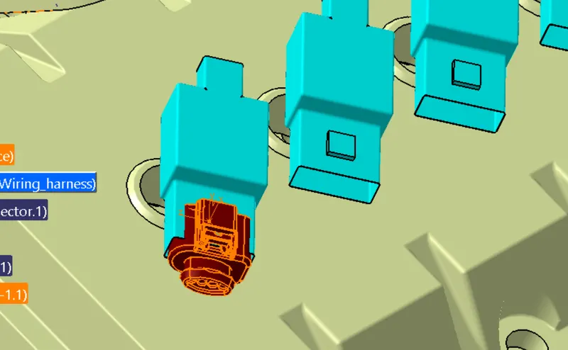
Now copy , paste and position the other connectors
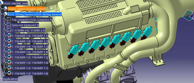
simmarly add on other side
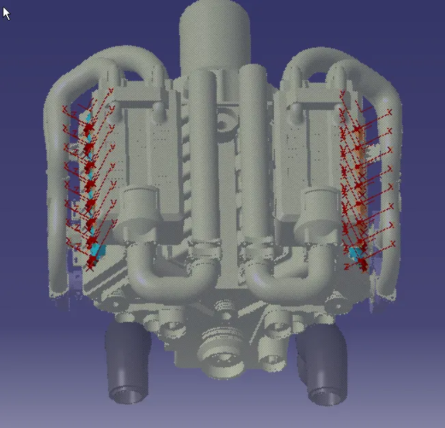
Now lets place connectors for valve timing / cam position,
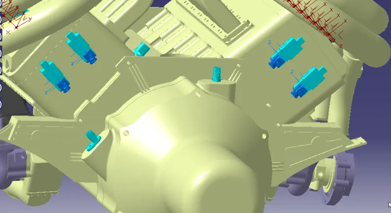
Now for oil temp sensor
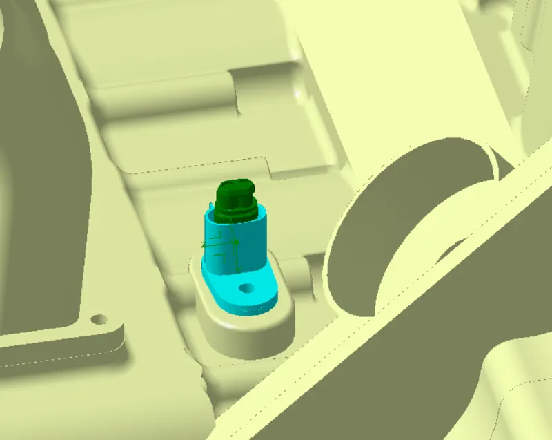
Speed sensor
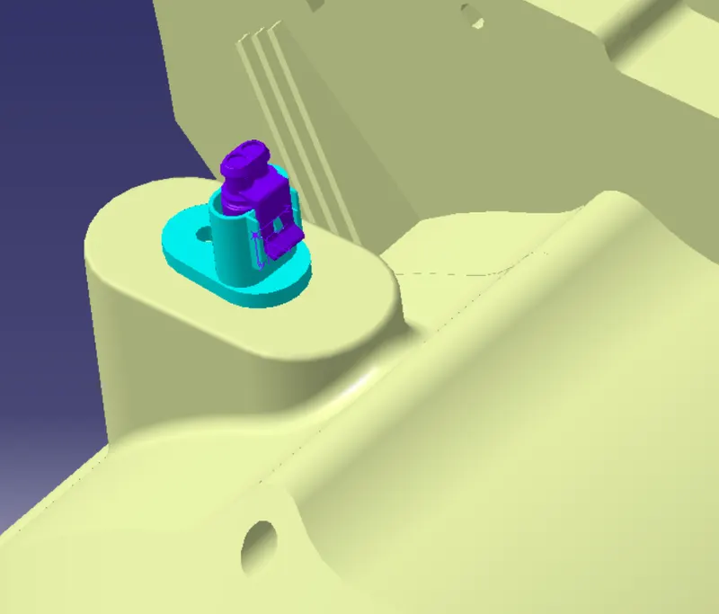
Neutral position sensor connector
Engine harness channel
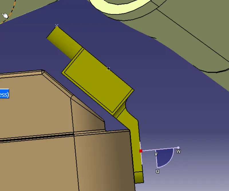
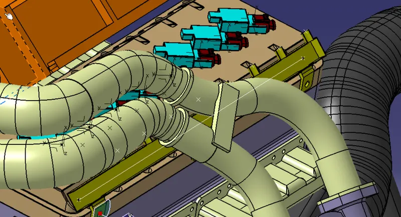
L clamp Positioning
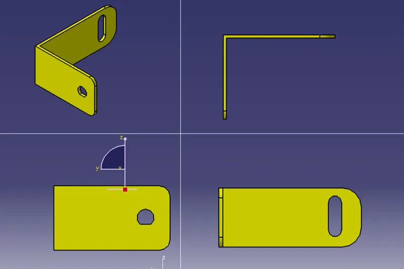
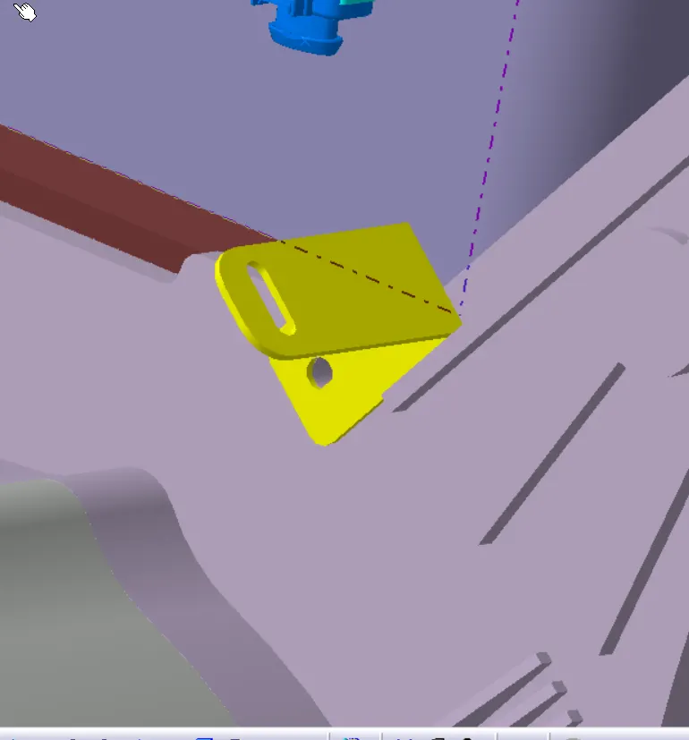
Supports :Clips and clamps
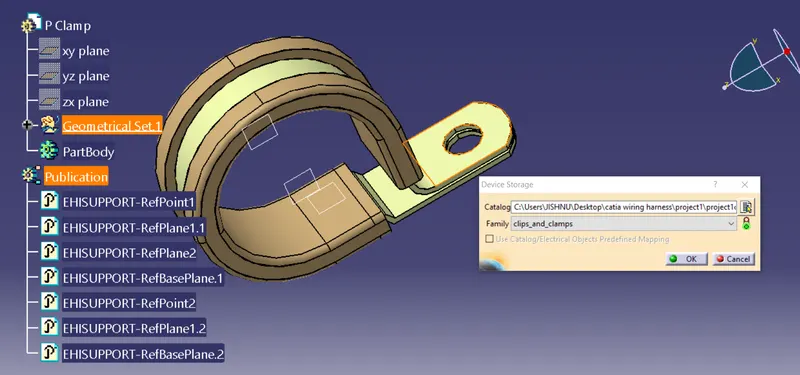
Pclamp
Create nessory points for bundle entry/exit and nessosry plane
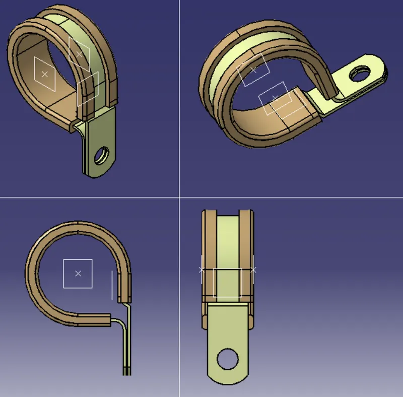
define as support,apply on both entry exitpoints
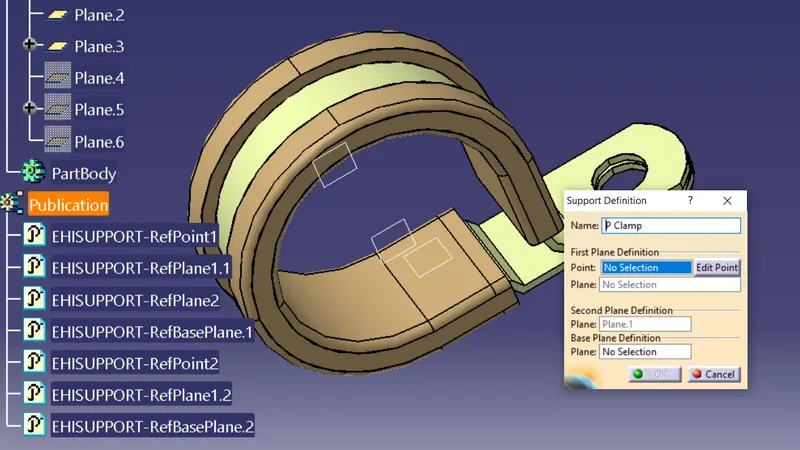
save and add to catalog famly clamps
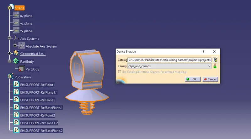
Firtree clip1
Create nessory points for bundle entry/exit and nessosry plane
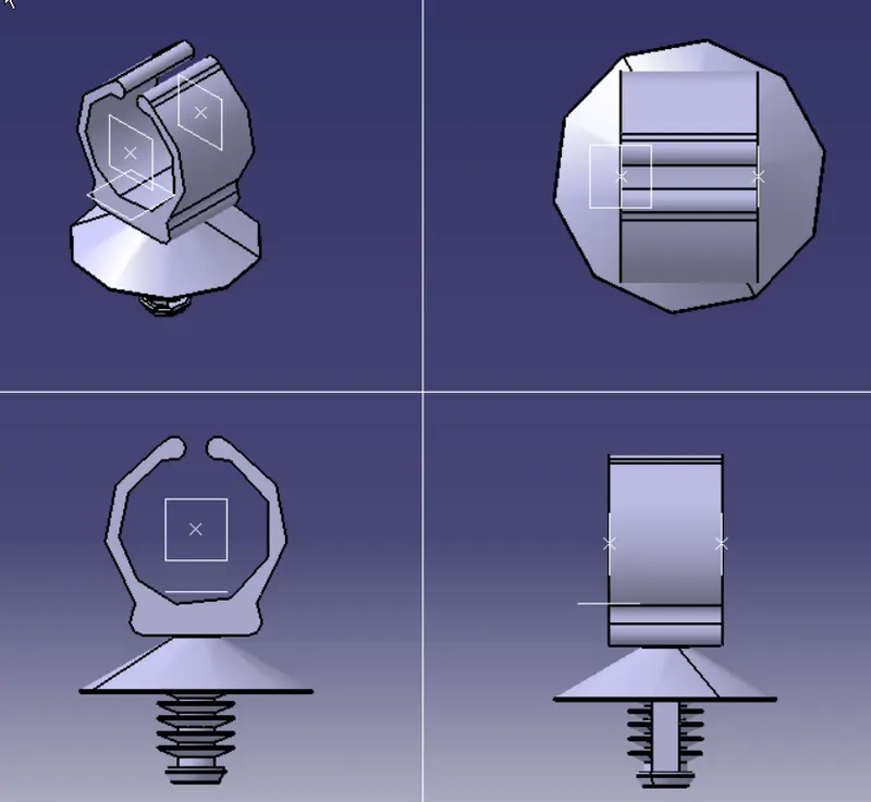
define as suppoet element
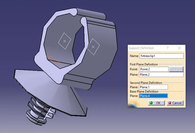
save and add to catalog
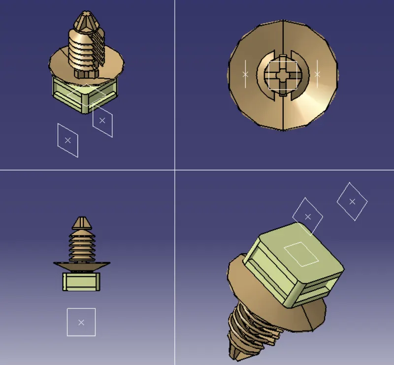
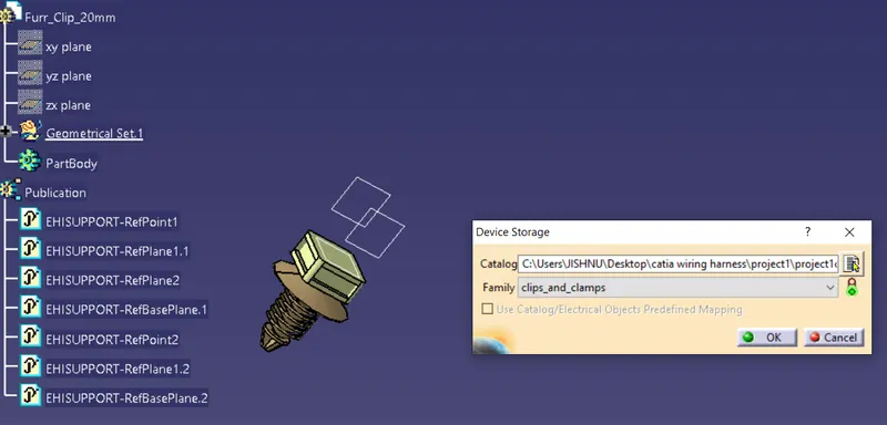
FirTree clip2
Create nessory points for bundle entry/exit and nessosry plane
Antirotational clamp
define all required points and axis
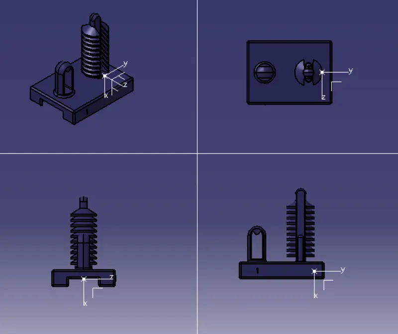
define cavity
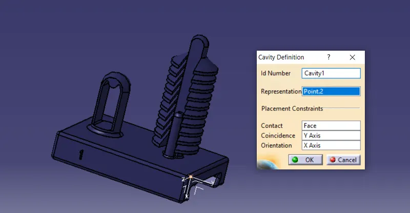
save and add to catlog
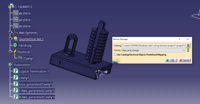
Protetive sleeve:
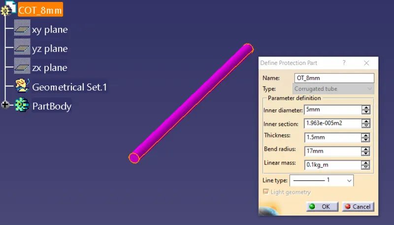
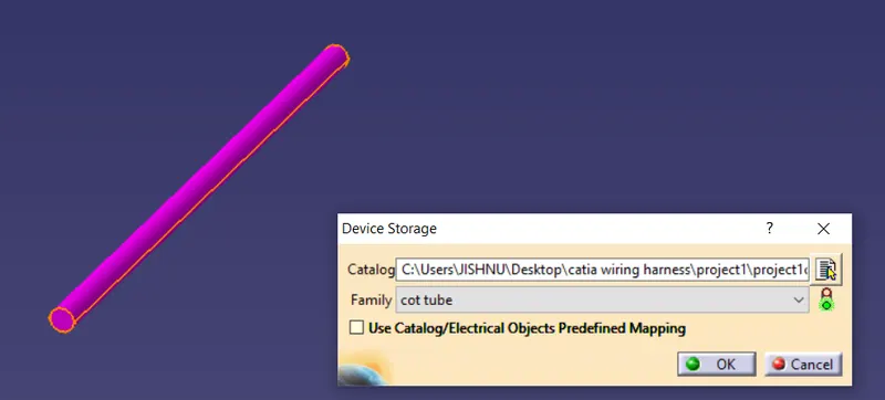
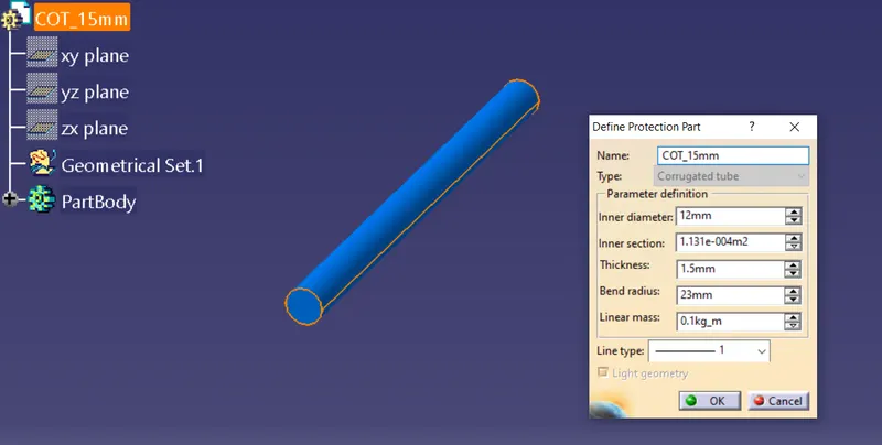
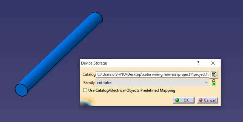
Creating protective sleeves
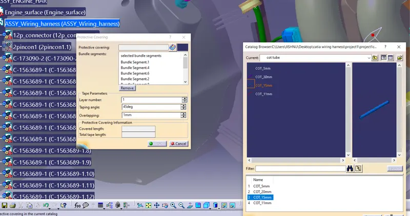
COT-5mm
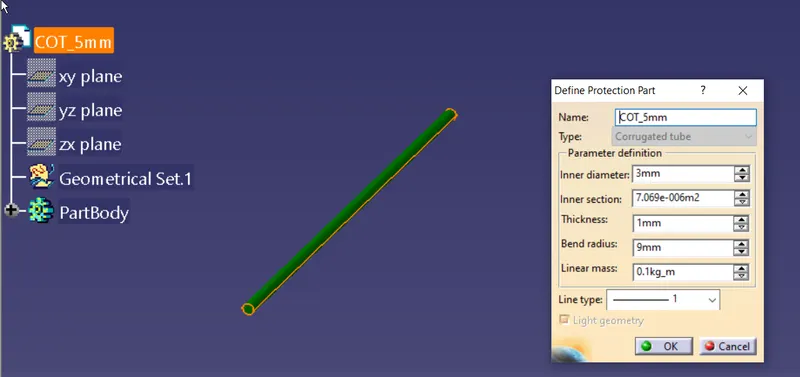
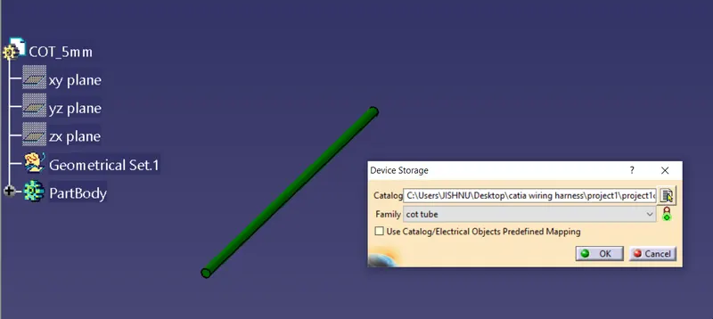
COT-8mm
COT-15mm
COT-11mm
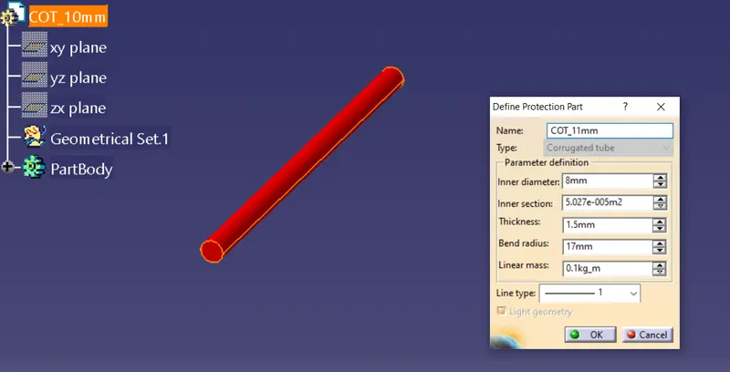
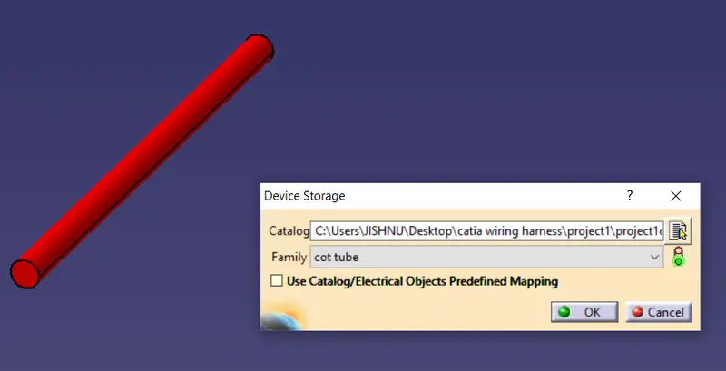
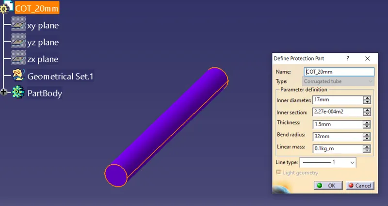
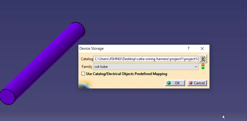
COT-20mm
Adding nessory clips and clamps for support
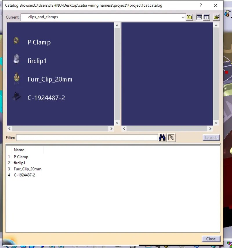
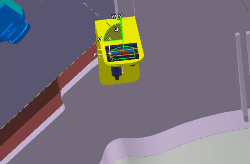
adding p-clamps
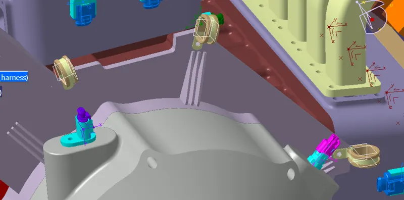
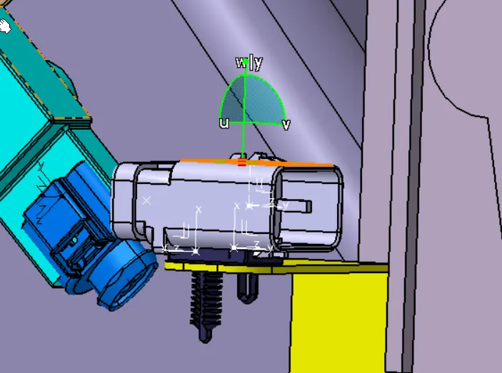
After all connector and support placement start wiring
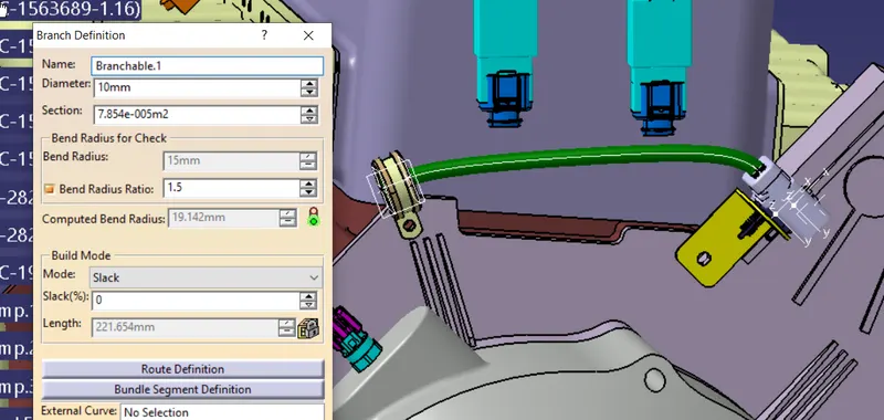
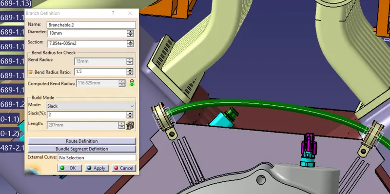
adding branch points
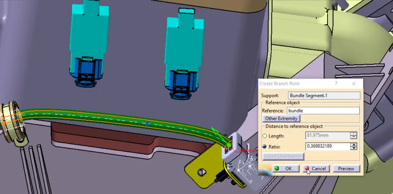
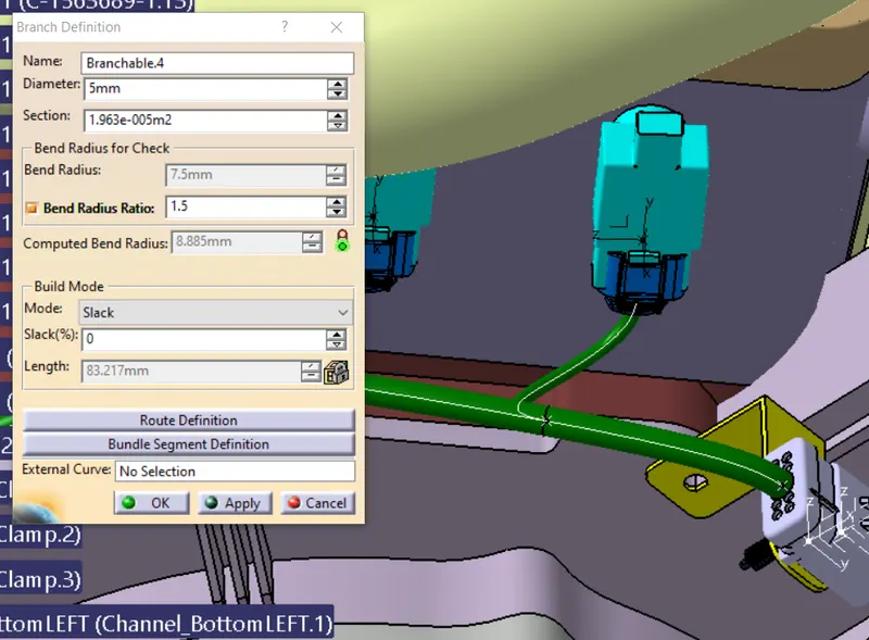
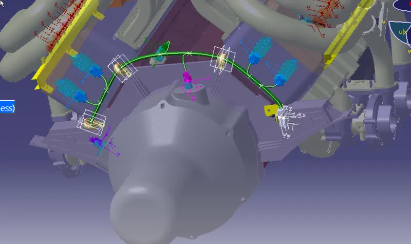
request for adding a firtree clip
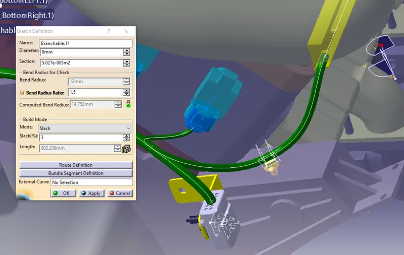
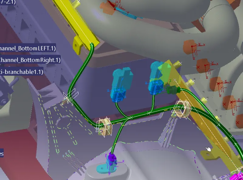
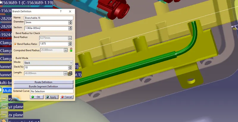
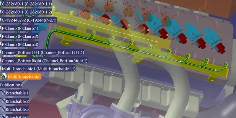
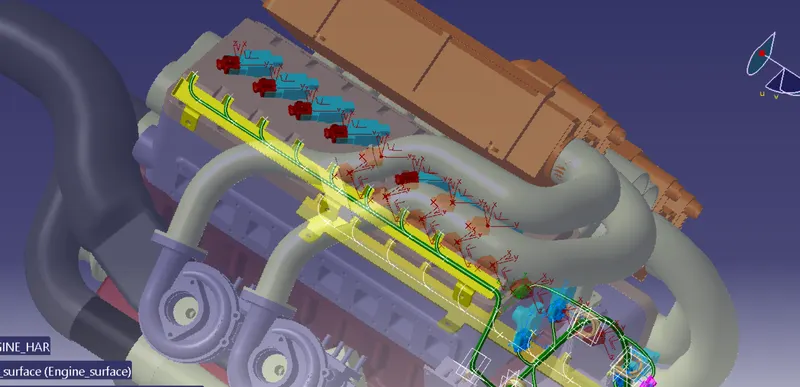
Adding harness in channel using curve
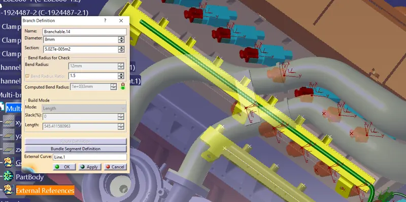
add branches
 \
now to connect chanel to injector
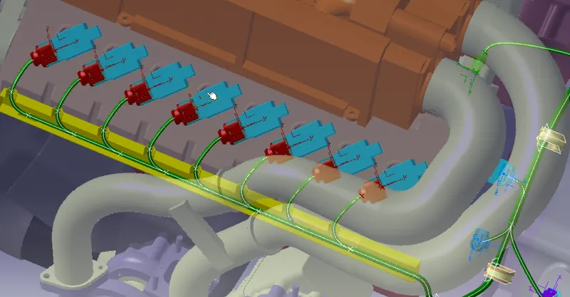
add top cover for chanels
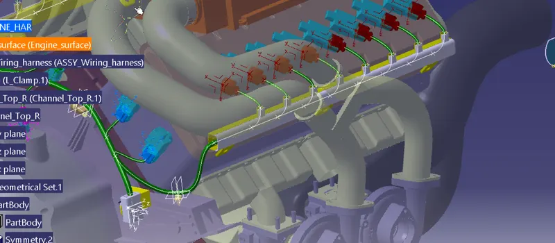
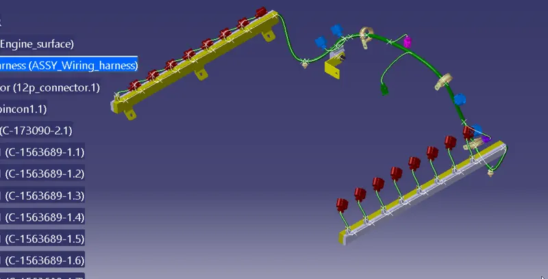
Adding protection tube to harness
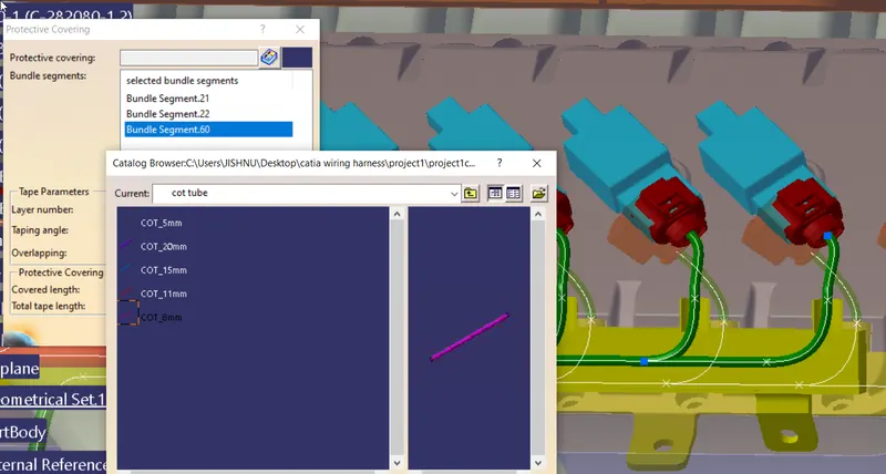
give min 30 mm end extrimity
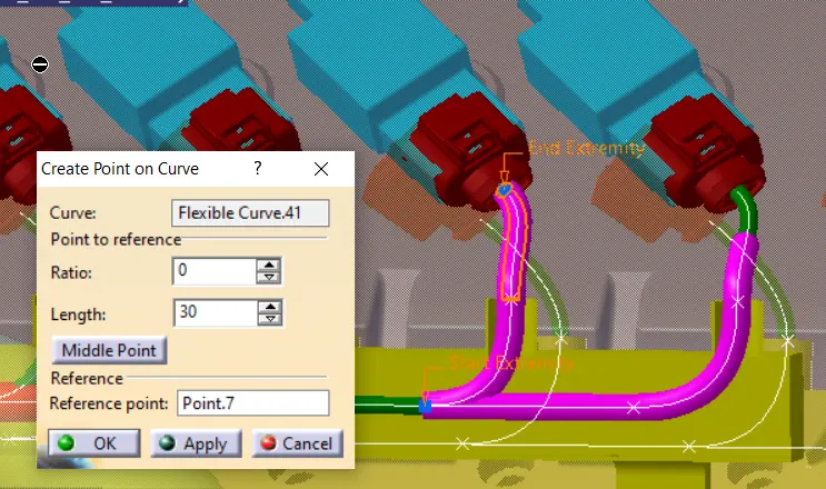
now complete on both sides
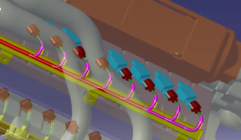
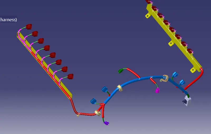
Check for any discontinuity
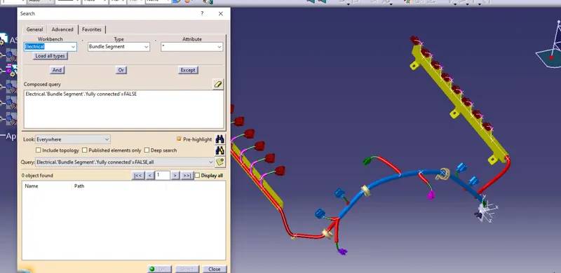
Creation of flaten assy file
Create a new product file to flatten
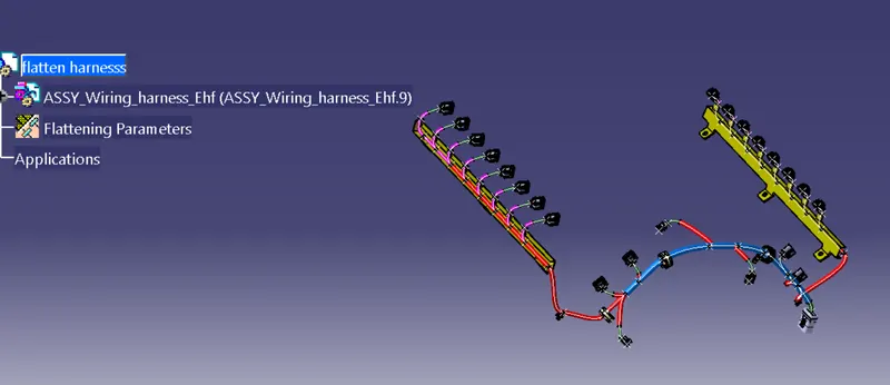
Use flaten command
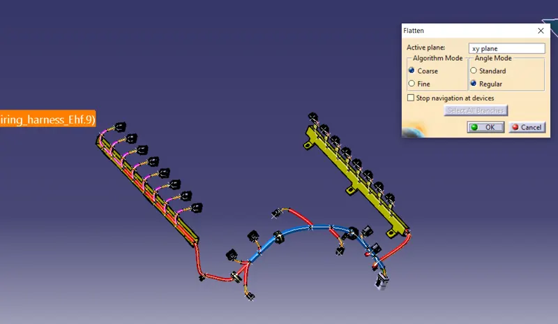
Adjust the angles of connector
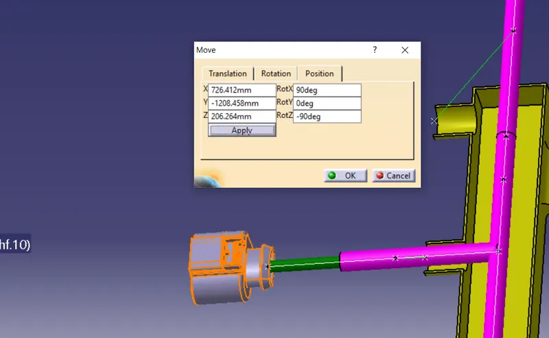
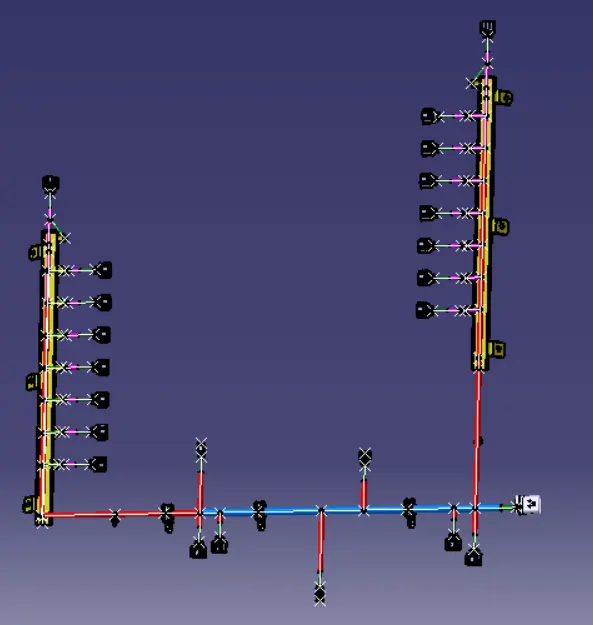
Note :as protection tube with in the chanel is not nesssory we could remove it . this may also increase stress on the pins on bundle entry point
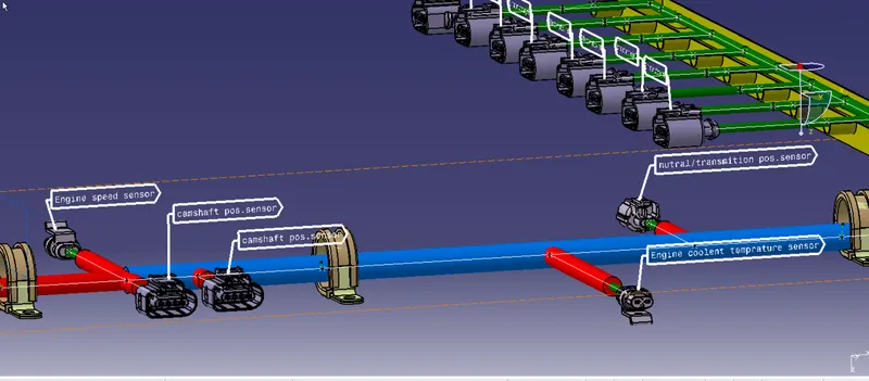
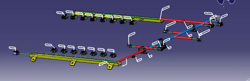
label all the parts for identification
Creation of wiring harness diagram
create a drawing file, add flaten assy file.
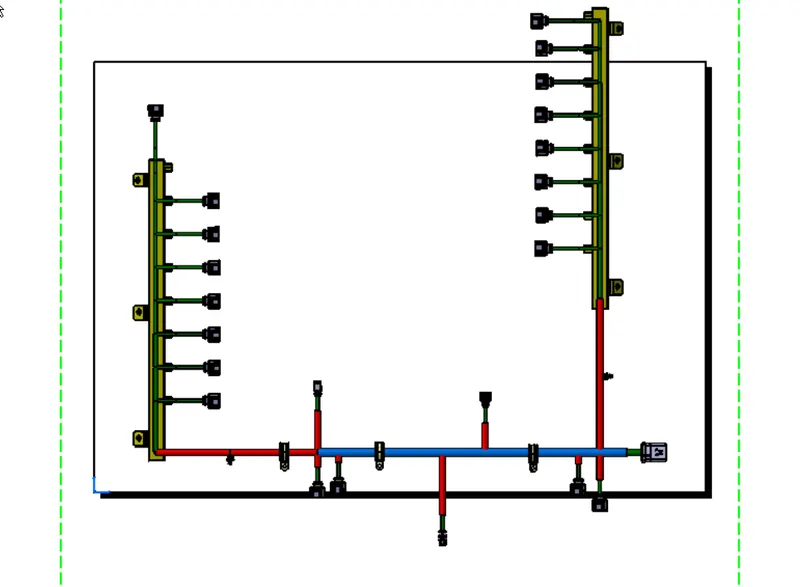
create backgroud label parts , create BOM
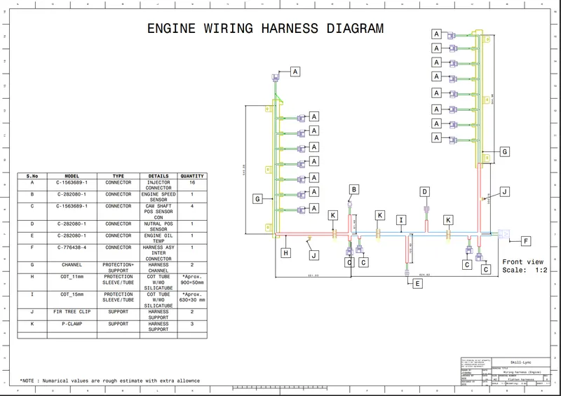
reference