Project 1
Route the Wiring harness on Given Engine and Prepare flatten view drawing in CATIA V5. Application of all Packaging rules, Industry best practices studied in this course shall be demonstrated in design. Apply Protection coverings as required.
A) Here the engine file is provided and that engine name is 'V16 ENGINE'. Why it is called V16 engine,because it have 16 injectors which are equally divided into 2 sections and they are in 'V' shape. That's why it is called as 'V16 ENGINE. First it was discovered in 1930. First it was used in pearless cars in 1932 and named as 'Peerless sixteen' and also it was used the only known use of a V16 engine in the post-World War II era is the British Racing Motors (BRM) V16 engine used in Formula One racing from 1950 to 1955. And it was also used in marine and aircarft applications. The below picture shows the V16 engine;
Assumptions-
- Provide clips/clamps as per requirement.
- Make sure that there is no any fauling case while designing the wire harness. Additional clips/clamps may be used to avoid fauling case.
- Give additional slack if needed. 5-10% slack is sufficient.
- Avoid routing over bolt and bolted joints to avoid harness puncture.
- Avoid routing on sharp edges or else provide protection over the harness.
- Follow the clearance distance and keep away the harness from heat generation components.
- Protection should be provided as needed according to surrounding temperature.
- Avoid direct support for harness on fuel lines routed in the engine.
- Use plastic guiding channels if needed.
- Branch length should be greater than 50mm.
- Minimum distance between two branch points should be at least 50mm.
- Minimum distance between clip and branch point should be at least 25mm.
- Avoid too many sheet metal brackets on the engine. Try to use available threaded bosses on the engine or demand for it.
- The wiring harness should be easy to assemble and easy to access.
- While using dummy connectors, ensure that whatever positions you are defining that are practical. Bundle diameters and another placements can be defined properly for the wire harness routing.
- If the packaging area is too tight and there are many packaging constraints then we can think of creating harness channel which can be used to route and protect the wire harness effectively.
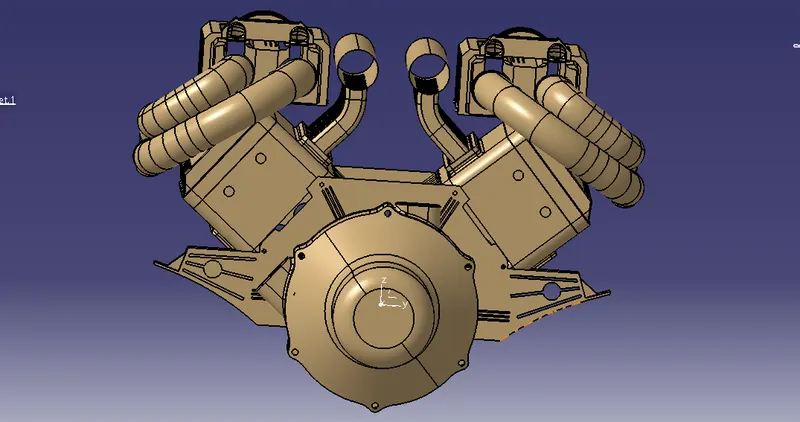
In this engine, we have 16 injectors,4 Cam shafts, 3 sensors and available holes for placing the Mounting Clamps, bottom shells
The parts or wiring harness components which are used for this engine is;
A) Connectors(2pole,3pole,4pole) B) Mounting clamps(Fur tree clips,P Clamps) C) Interconnecting-Connector
D) Bottom Shell E) Convoluted Tubes
A) CONNECTORS: Connectors is electromechanical device which is used to joint bunch of wires together and connects to circuit. The connectors are varied based on their entry poles like 2-pole connector,3-pole connector, 4-pole connector etc---The connectors which we used for this engine is shown below;
4-POLE CONNECTOR: For all injectors and camshafts we used this connector only. Because for injectors and camshfats we need to use the 4 pole connector.
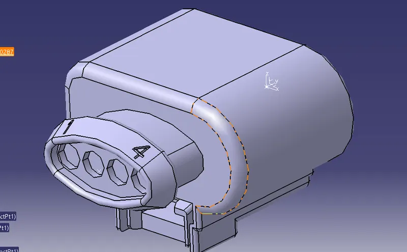
2 - POLE CONNECTOR: This connector is used at the 3 different sensors because when we don't have required connectors, we can use dummy connectors for routing and when the required connectors are available we can replace it.
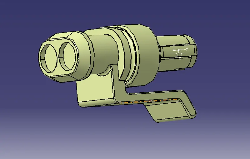
B) MOUNTING CLAMPS: These are used for to give support the wires while we doing the harness process like P-clamps and furr tree clips and they shown below;
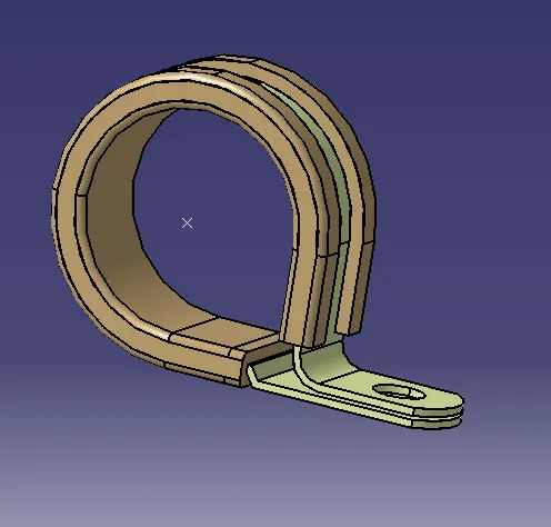
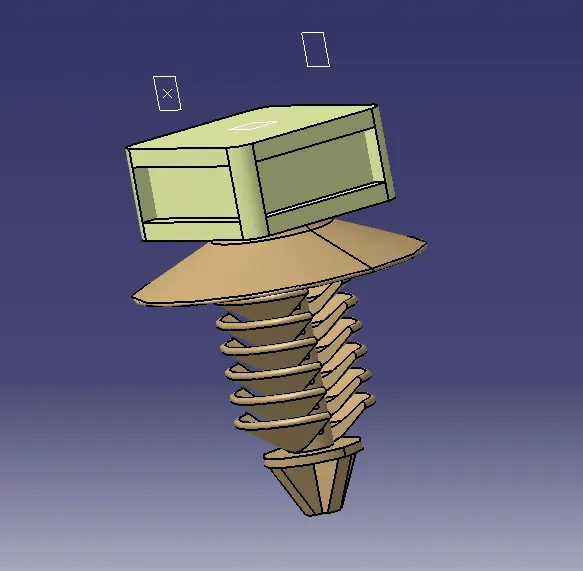
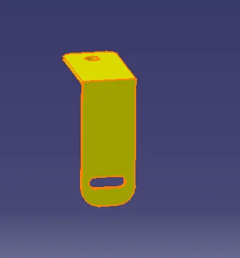
C) INTERCONNECTING CONNECTOR: This is used to connect the engine wiring harness and vehicle/chasis wiring harness. We will place this one on the engine with the help of L-Clamp which was shown below;
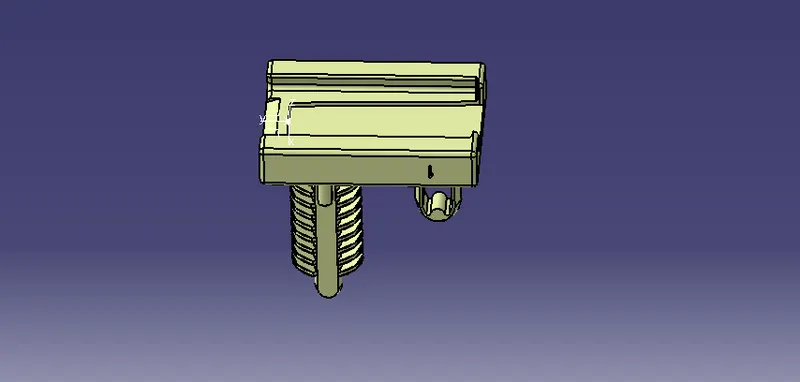
And we will place the connector and connector clip which is used to give support the connector and it will be fixed in the engine. The connector and connector clip are shown below;
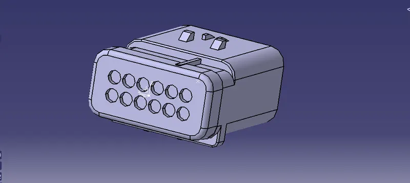
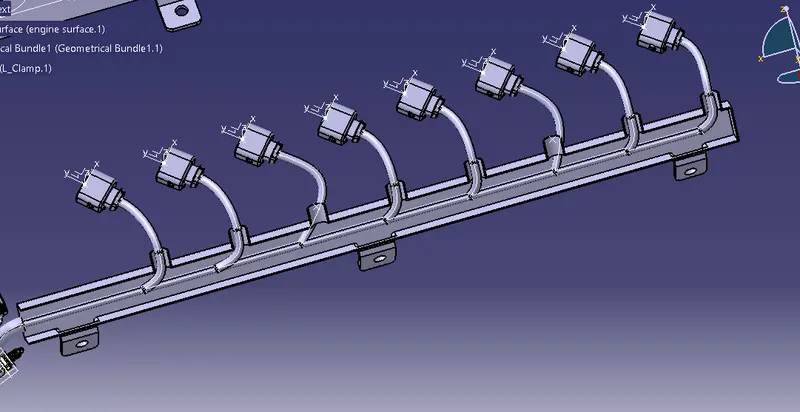
D) BOTTOM SHELL: This shell is placed at both sides of connectors which is used to connect the wires main bundle and shown below;
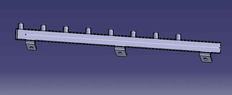
We have seen the components which we used for this project. Now we will look at the placing of these components on this engine.
CONNECTORS:
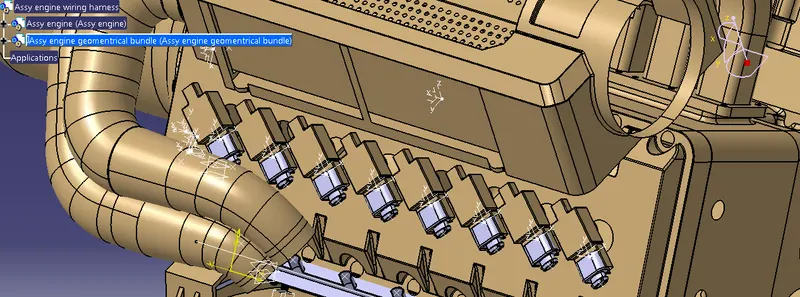
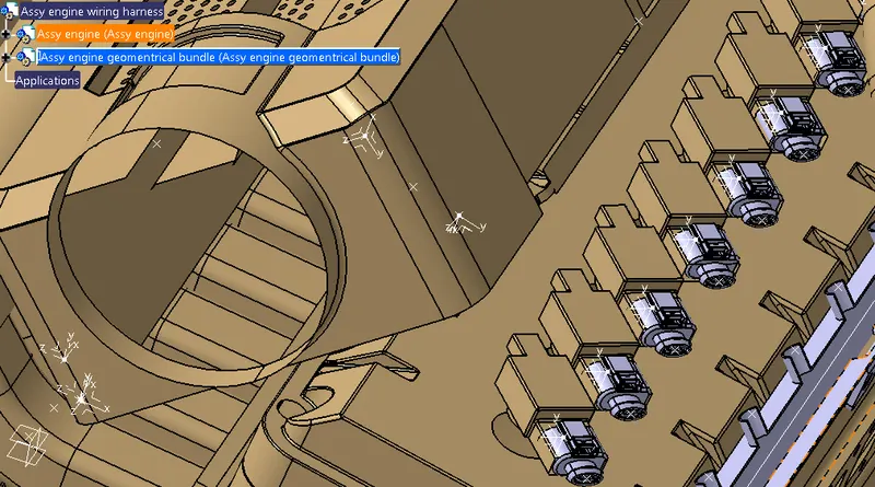
BOTTOM SHELLS: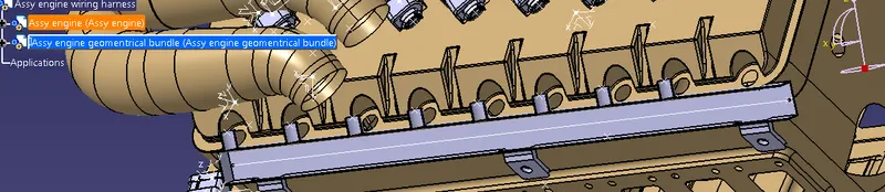
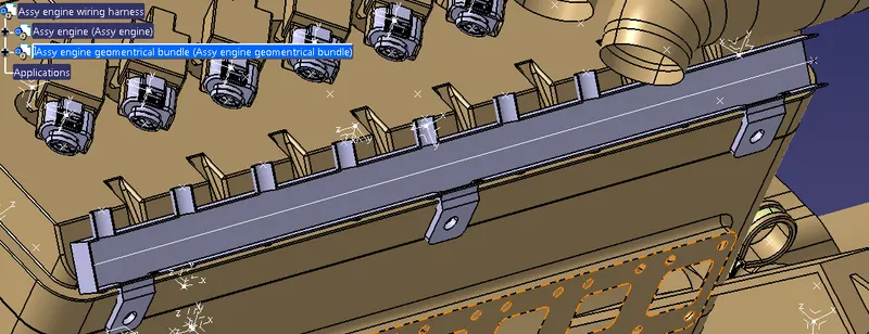
CAMSHAFTS:
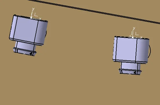
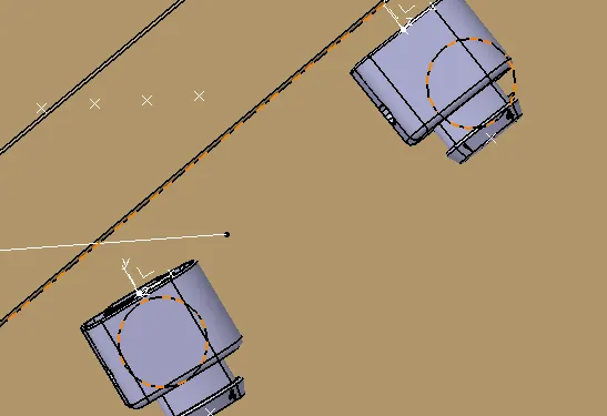
COOLANT SENSOR:
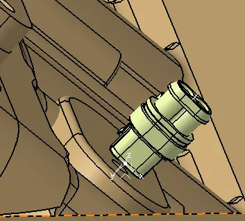
ENGINE SPEED SENSOR:
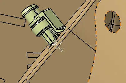
INTERCONNECTING CONNECTOR: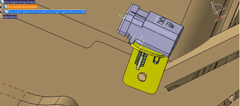
NEUTRAL POSITION OF TRANSIMISSION:
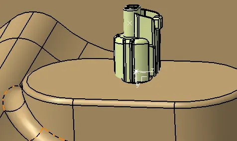
P-CLAMPS:
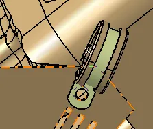
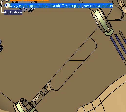
FURR TREE CLIPS:
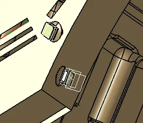
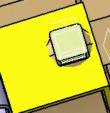
One important thing is placing the L-clamp should be done very carefully. We cannot fix directly the clamp, we need to do it with the help of screw and we should fix it on the screw. And another thing placing the L-clip and it should not move , it means we should pplace this one where the suorunding will provide a barrier to rotate it. So we placed L-clamp based on thse conditions.
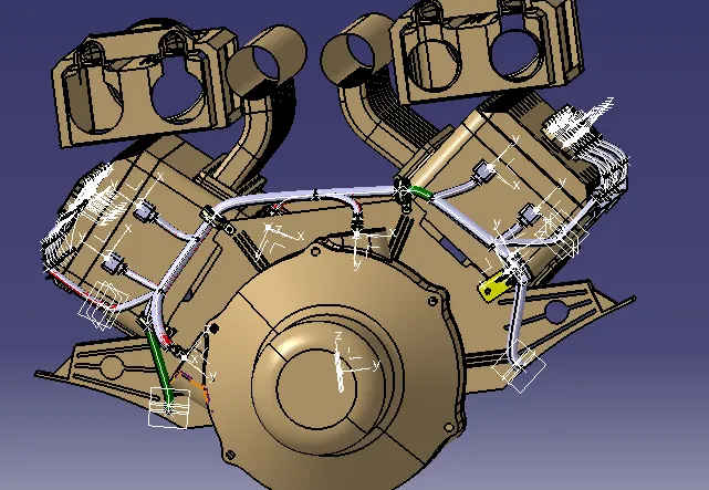
ROUTING: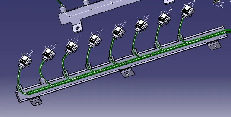
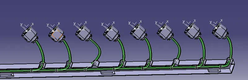
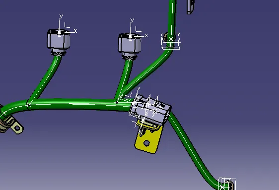
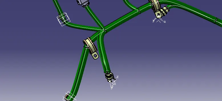
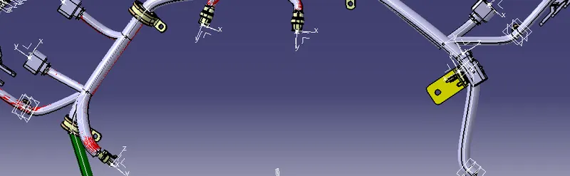
After completion of routing we need to add protection coverings, it protects the from any cause damage.
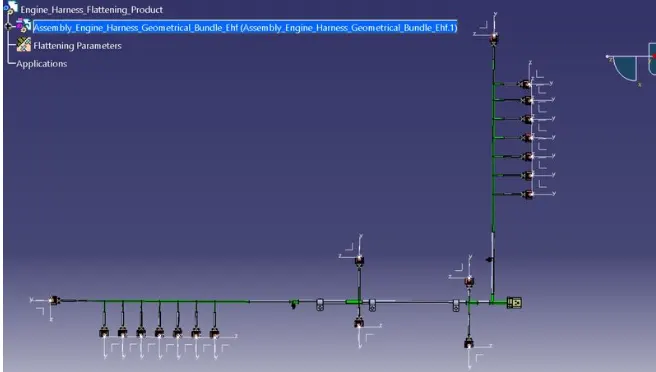
After completion of routining and protection covering the next step is doing the flattening process by using the 'Electrical Flattening Assembly' and the flatten figure is shown below;