Project 1
'WIRING HARNESS ROUTING DESIGN ON V16 ENGINE'
Aim of Project:
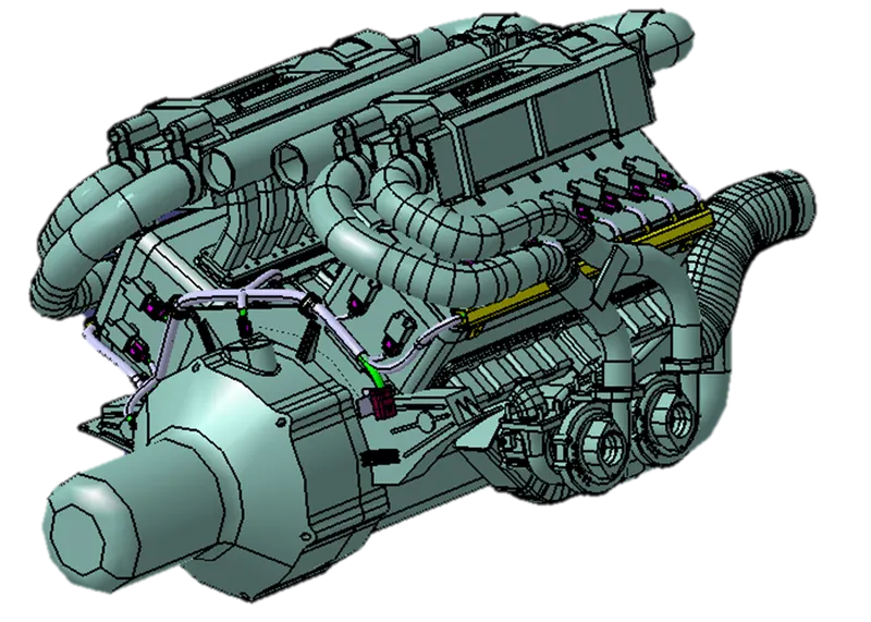
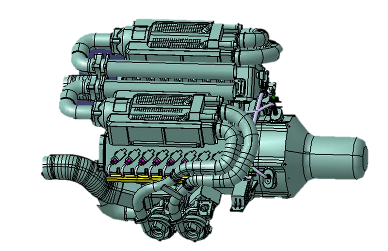
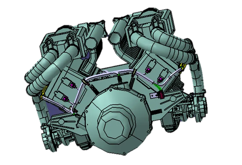
To Design and develop the Wiring harness on Given V16 Engine and Prepare flatten view drawing in CATIA considering all industrial packaging rules.
Input:
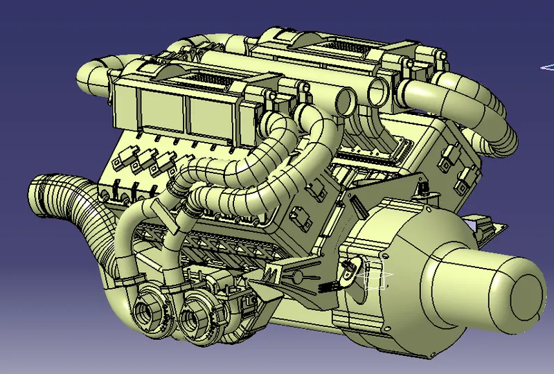
A V16 engine is a sixteen-cylinder piston engine where two banks of eight cylinders are arranged in a v configuration around a common crankshaft. V16 engines are less common than engines with fewer cylinders, such as V8 and V12 engines. Each bank of a V16 engine can be thought of as a straight 8 a design that can be inherently balanced Most V16 engines have a 45° bank angle.
V16 engines are rarely used in automobiles because V8s or V12s of the same displacement produce just as much power, but are much less expensive to manufacture and maintain.Today, the most common applications for V16 engines are railroad locomotives, marine craft, and stationary power generators.
Technical specifications :
- No of injectors : 16
- No of cam shaft sensors: 4 (2pole connectors)
- Type of connector used in fuel injectors: 4 pole connector
- Type of interconnection connector : 12 pole electrical connector
- Maximum withstanding temperature of plastic guide channel: 150°C
- Bend ratio for bundle segments : 1.4
Some important packaging rules to be considered during wire harness routing:
- The minimum distance between two clamps on a straight branch should be of 200mm.
- The minimum branch length should be 50mm.
- The minimum distance between clip and nearest branching point should be 25mm.
- The minimum distance between two straight connection points should be 200mm.
- The minimum distance between two breakout points should be 50mm.
- We have to limit the number of branches from a single branch point to 4.
- We need to avoid routing wiring harness near the exhaust manifold and its components and also from other unshielded heat sources. If re-routing is not possible then maintain a minimum distance of 200mm.
- We also need to see that too many metal brackets on engine are avoided and we should use the available threaded bosses on engine.
- We have to provide clamps to ensure positive clearance with surroundings and safety of wiring harness.
- P - Clamps, Fir tree clips and other clips can be added to the Geometric bundle as they are electrically defined and are part of the Wire harness routing and should be provided with the Wire bundle package.
- We have to provide slack (8-10%) should be provided to the wiring harness which can maintain any kind of tension in wires and connectors during movement.
- The wire harness routing should be done in such a way that it is easy in manufacturing and serviceability.
- We have to avoid sharp edges on the sheet metal parts and if it is not possible then provide protective coverings like cot tubes,breaded tubes or tapes to prevent damage of the wire bundle.
Introduction:
An engine wiring harness is an organized set of wires, cables, connectors and terminals that controls a vehicle’s electrical system. Engine wire harnesses relay electrical power and control information to outlying components such as:
- Alternators
- Audio Systems
- Batteries
- Blower Motors
- Computers
- Fuel Injectors
- Fuses
- Windshield Wipers
- And everything else that is controlled electrically that we can find in a vehicle
Even the active and passive safety systems in automobile are connected electrically with ecu with the help of wire bundles ,sensors and connectors.
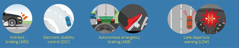
Active Safety Systems
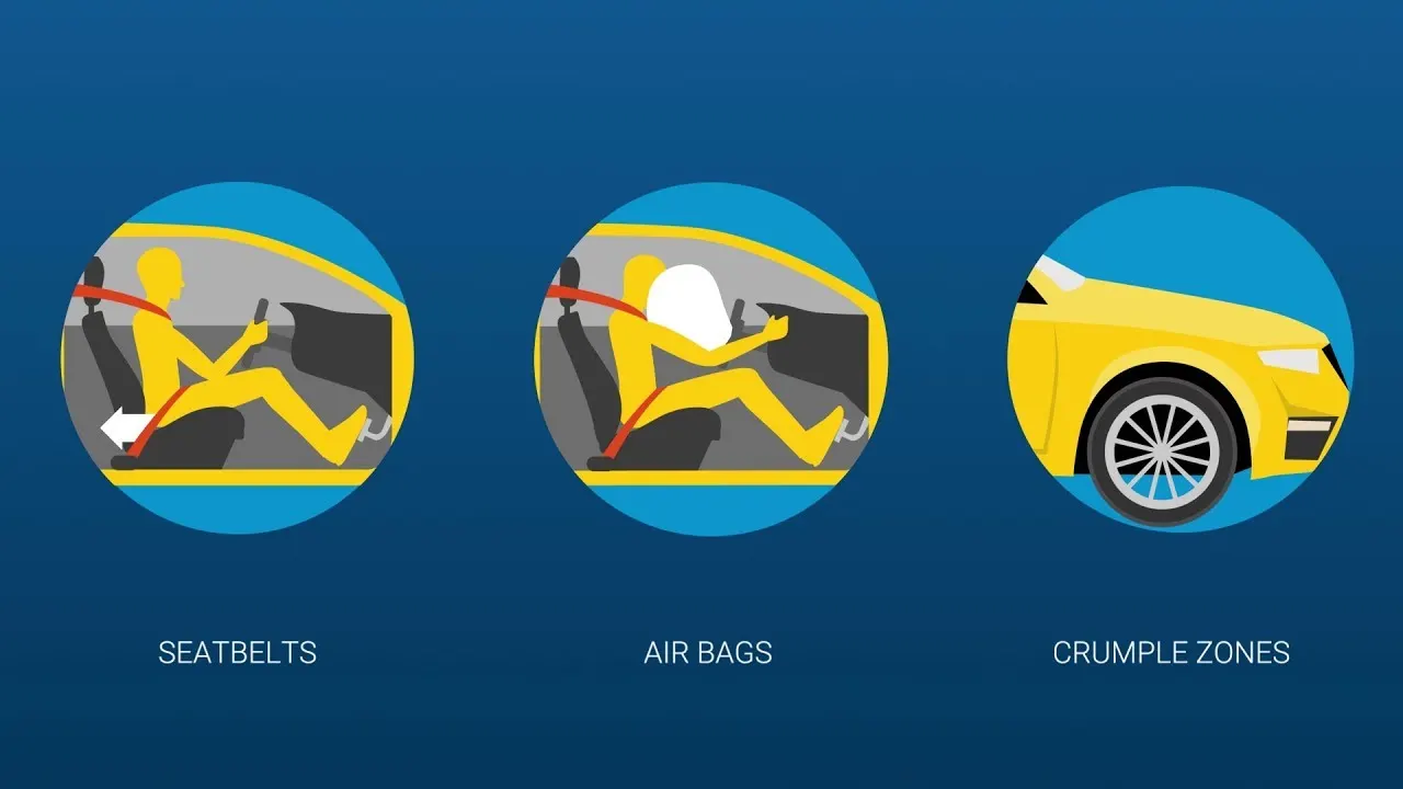
Passive safety systems
A wiring harness, is an exterior sheath used to cover some types of electronic wires. Generally, wiring harnesses are made of thermoplastic or thermoset materials that can help protect the cables from the high temperatures and other foreign particles such as water,lubricants etc.
DESIGN METHODOLOGY:
Step 1: We have to Create a Context Assembly which will work as main assembly and it will contaim Engine data and harness geometrical bundle assembly and any other sheet metal parts can also be added to context assembly.
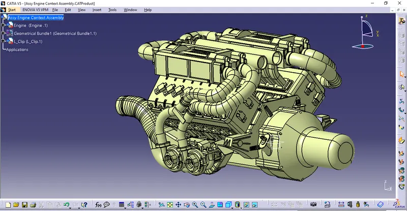
Assy engine context assembly containing engine,wiring harness geometrical bundle and L clip sheet metal part .
Step 2: We have to define all the mechanical connectors and other clamping parts electrically in electric part workbench and save it in the Catalogue so that we can use it next time in some other project.
1) C-173090: No of termination is 2
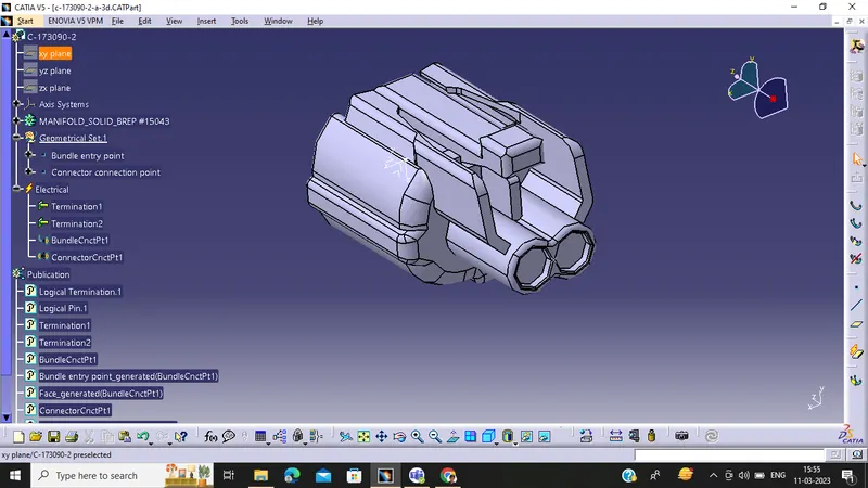
Electrically defined
2) 282080 : No of termination is 2
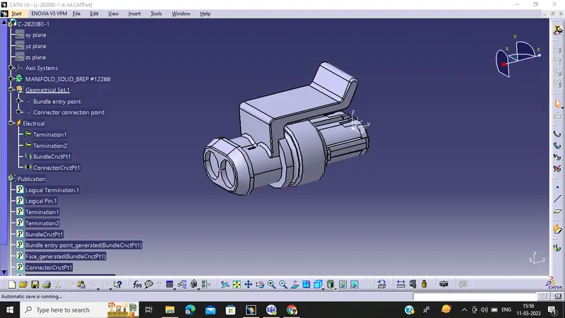
Electrically defined
3) Interconnector C-776438 : No of termination is 12
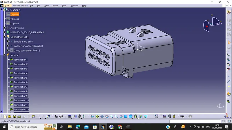
Electrically defined
4) C-1563689 ( Injector Connectors) : No of termination is 4
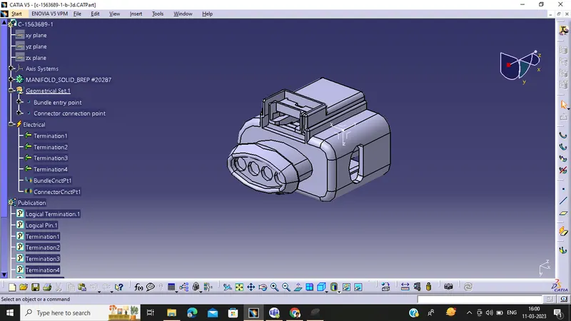
Electrically defined
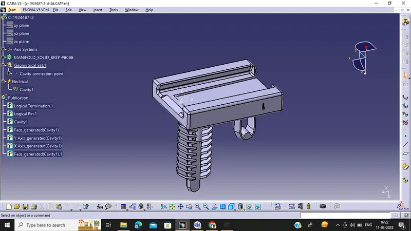
5)Mounting cavity "C-1924487-2
Electrically defined
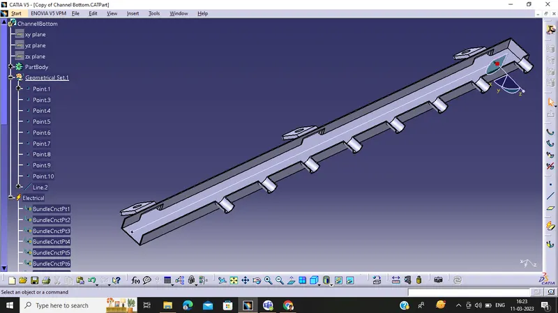
6) Channel Bottom LS
Electrically defined
We will also create Channel symmetrical assembly and define the symmetry bottom channel electrically using define mounting equipment option and also create all the required geometrical parameters on it.
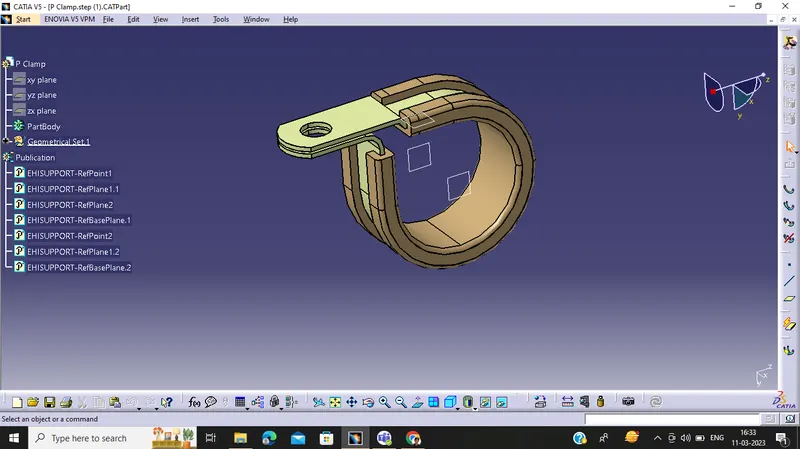
7) P Clamp
Electrically defined
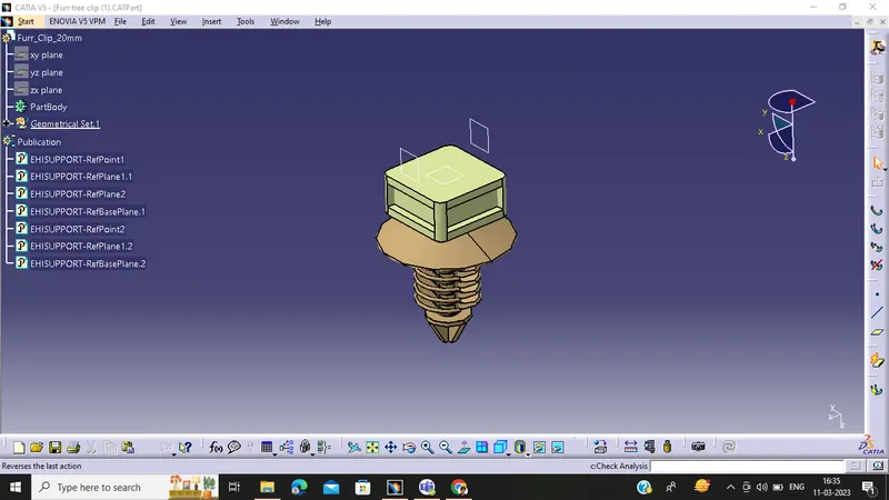
8) Furr Tree
Electrically defined
Step 3: We have to create a catalogue for connectors.
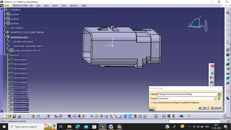
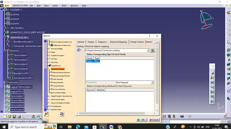
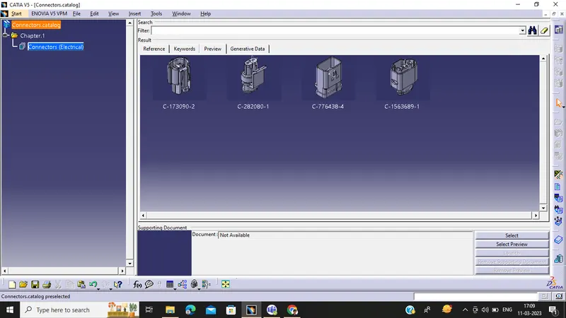
Connectors Catalogue
Step 4: We have to place all the connectors to the required positions on the given engine 3D CAD model along with all other necessary mounting equipments
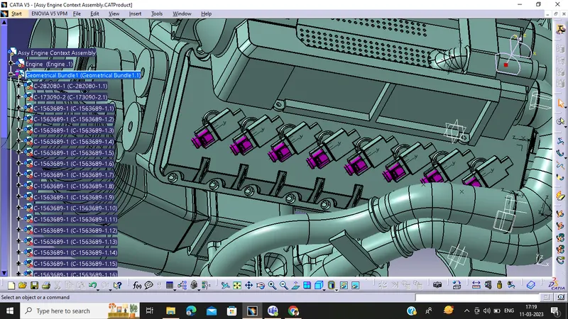
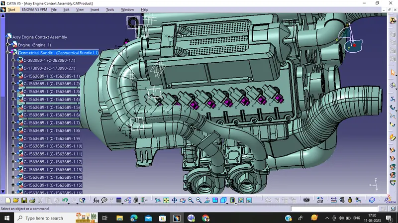
Fuel Injector Connectors placed on 16 cylinders
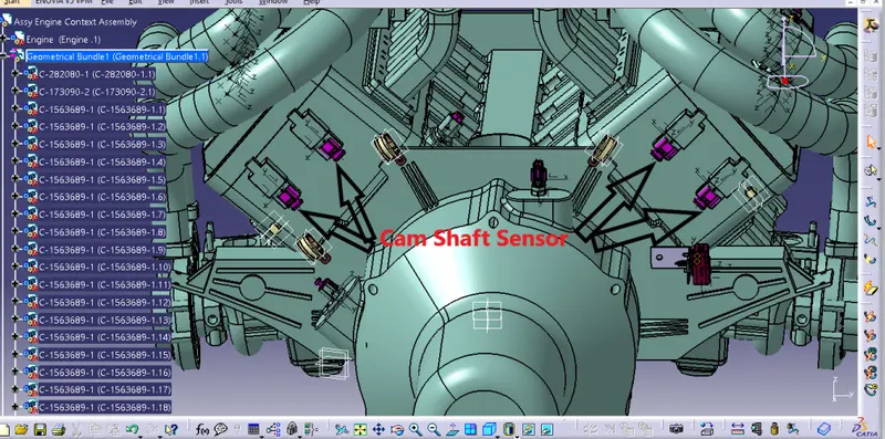
4 Cam shaft Sensor
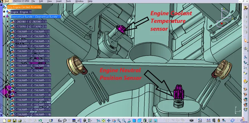
2 Pole connectors placed above
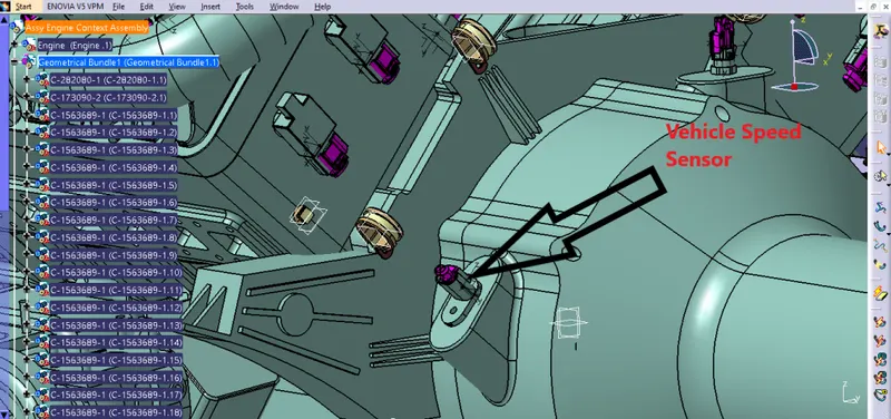
2Pole connector is placed above
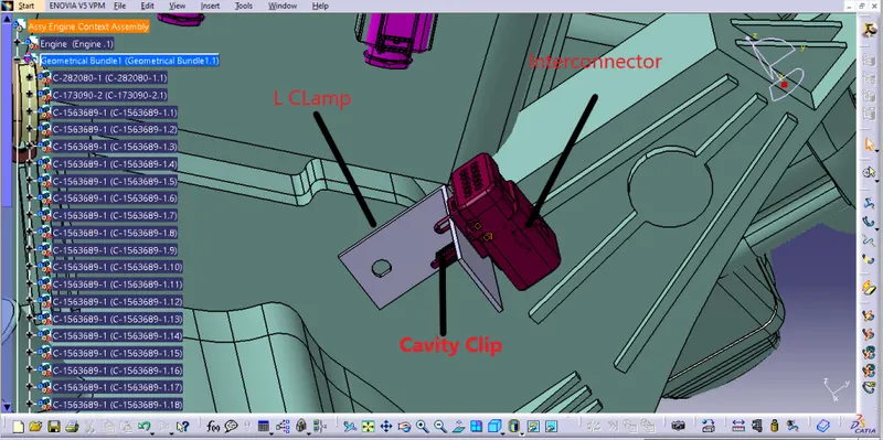
Interconnector electrically attached with cavity clip placed on L Clamp
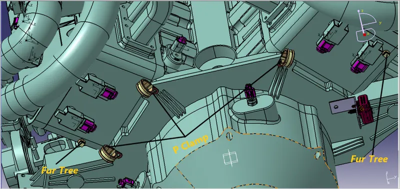
P Clamp & Fur Tree
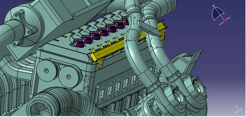
Channel Bottom Plastic cover placed near injectors
Step 5: We have to route connection in 'ELECTRICAL HARNESS ASSEMBLY' workbench
The Bundle routing starts from Interconnection connector to 3 P-clamps. The diameter for this routing path is 15mm and bend radius ratio is assumed to be 1.4 whereas for other areas i have used 10mm and 5mm bundles.
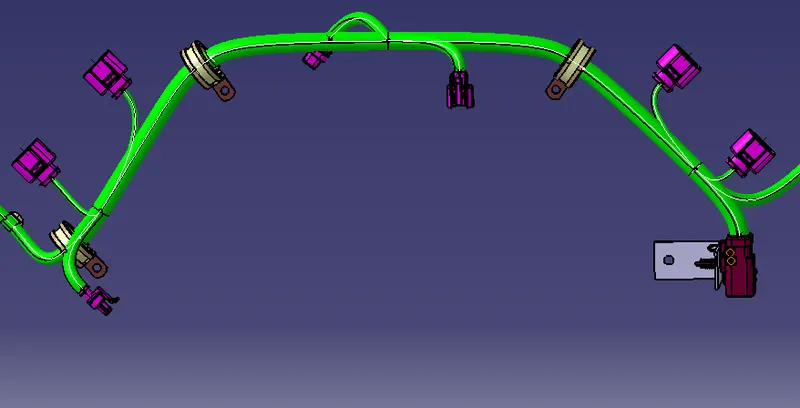
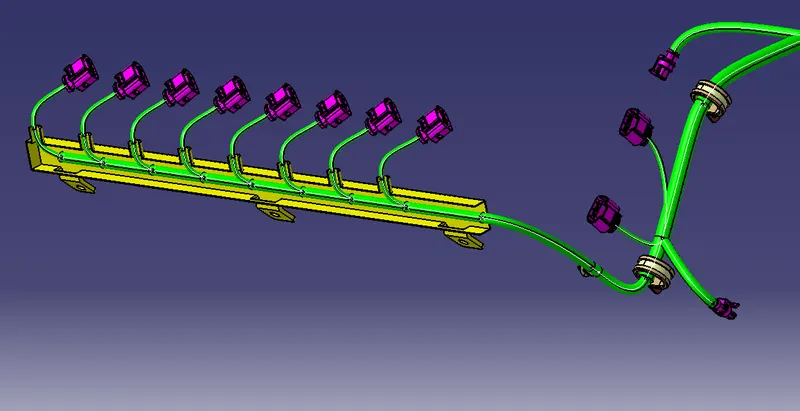
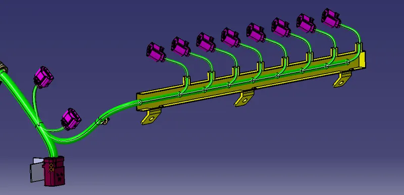
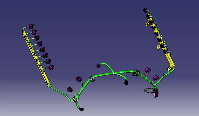
Step 6: We have to add protection coverings in the bundles like Corrugated Tubes
Steps to create Corrugated tubes:
1) we have to switch to electrical part design
2) Then select Define protection part
3) Click on part in specification tree
4) Then finally we need to provide the given parameters such as inner radius , bend radius and thickness etc '
#Note: Bend radius will be 1.5 times the outer dia of tube
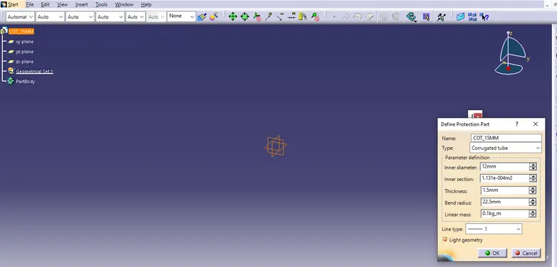
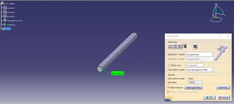
Tubes like this will be created
We can create different Corrugated tubes with diameter of 20mm,15mm,10mm,5mm etc and store it in catalogue
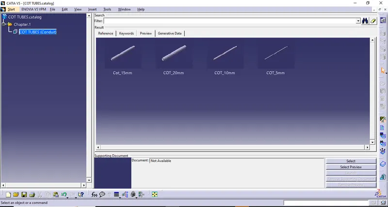
Cot Tubes stored in catalogue
Now we can add protective cover over wire bundles in geometrical bundle assembly.
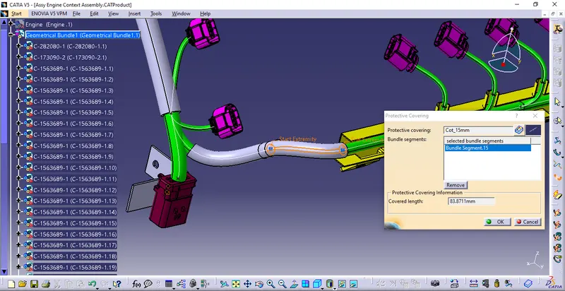
Adding Protective covering from the catalogue
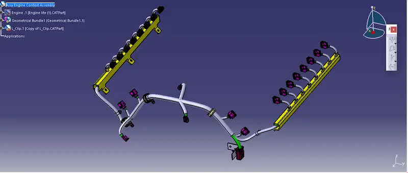
Protective coverings added on required places
Step 7: We have to perform Bundle Continuity Check ,We have to make sure that multi-branchable is selected then we have to click on Edit>Search>Advanced>Workbench-Electrical>Type-Bundle Segment>Attribute-Fully Connected and give 'FALSE' condition so as to see any bundle discontinuity
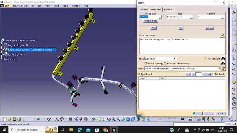
False Condition is reflecting null elements that means there is no bundle discontinuity
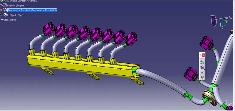
The top cover is also placed now
Step 8: Flattening :
After wiring harness Bundle packaging process is done.We need to convert the geometrical bundle into a flattened wiring harness in the Electrical Harness Flattening Workbench.
- To create the Flattened Harness, we need to create a new product file and switch into the electrical harness flattening workbench.
- Then we need to define the Harness Flattening Parameters and then Extract the geometric bundle from the wiring harness context product file.
- Then select all the branches and flatten the entire Geometric bundle.
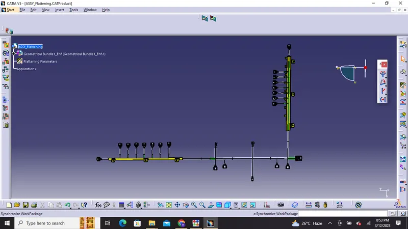
Then we need to rotate the bundles as required
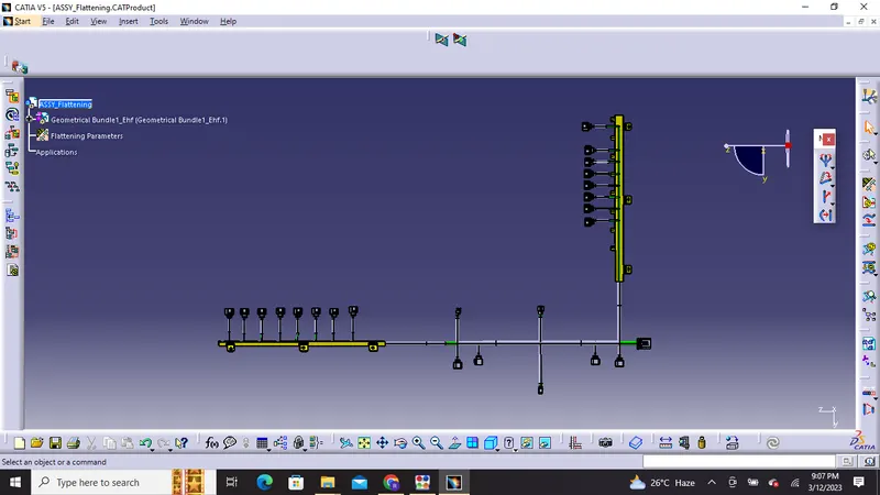
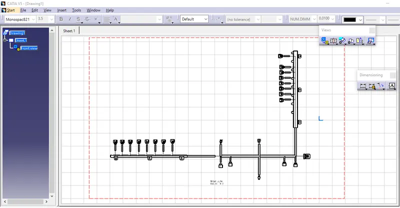
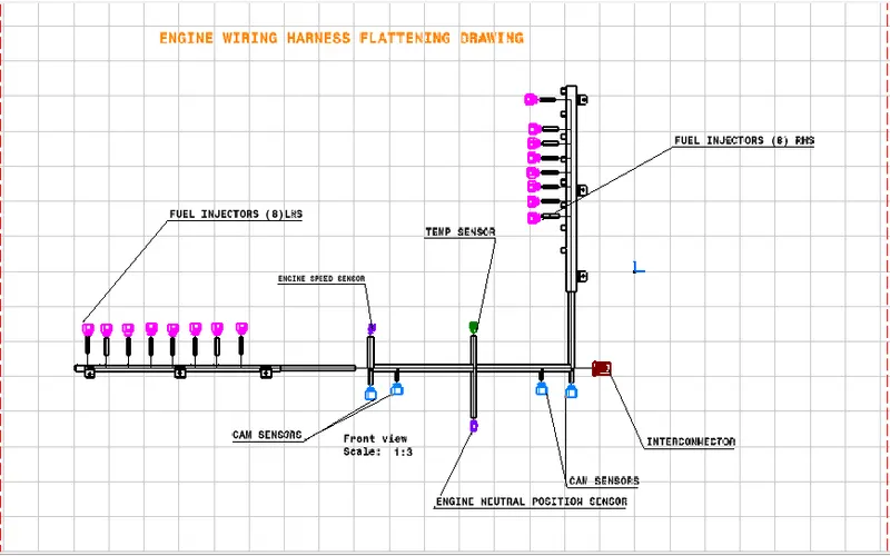
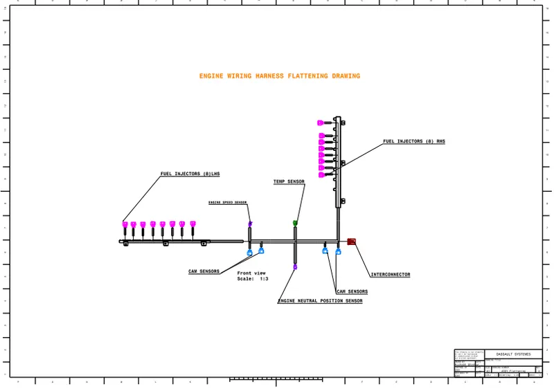
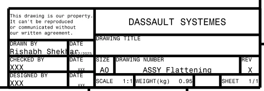
Drafting: Finally Preparation of drawing is carried out in drawing workbench
Output:
Thank You!