Project 1
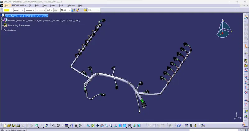
Engine Harness Assembly and Rouning
A wiring harness Routing is a 3D representation of the Electrical component's actual placement of the newly developed components. The harness shows how the bundle flow to the given part and how to pass the electrical signals from one end to another end and how long bundles are needed to route the harness given the mechanical parts. To consider the clearance of the harness, Avoid vibration and ratling, Failure analysis, Temperature management, and Ingress protection. Using clips/clamps and protection covering, insulation. This factor is considered to route the physical harness.
Wiring Harness Routing:
Wiring harness routing is described as the path of the wiring harness into a given vehicle environment by applying a set of design rules and industry standards.
Wiring harness packaging:
- Injector connector.
- Camshaft sensor.
- Engine Coolant sensor.
- Temperature Sensor.
- Vehicle Speed Measure Sensor.
- Nural Position Sensor (Transmission).
- Supporting Angle.
- Plastic Channel.
- P-clip.
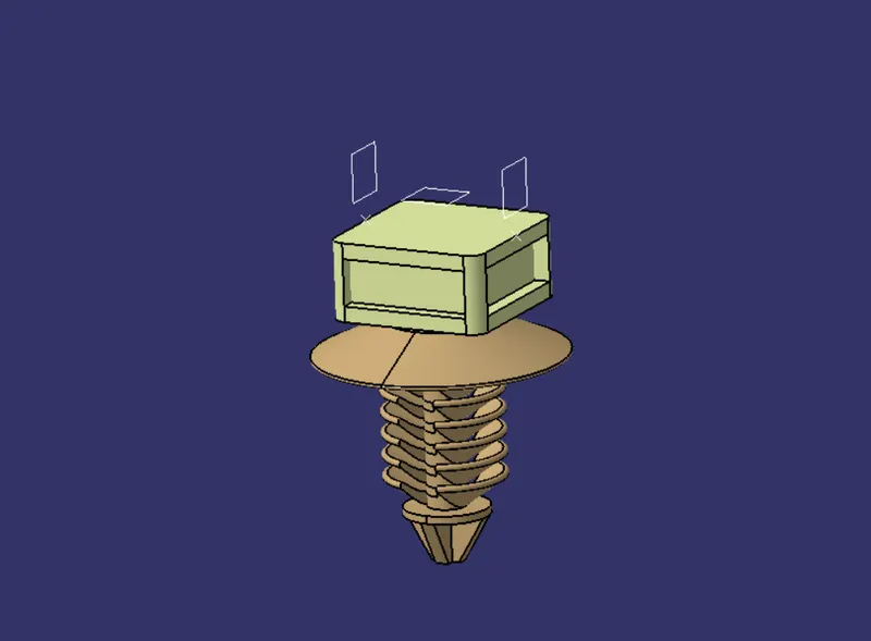
- Furr-Tree clip.
- Anti-rotational clip.
- Protection Tube.
- Cotton Insulation.
- Wire.
Connectors:
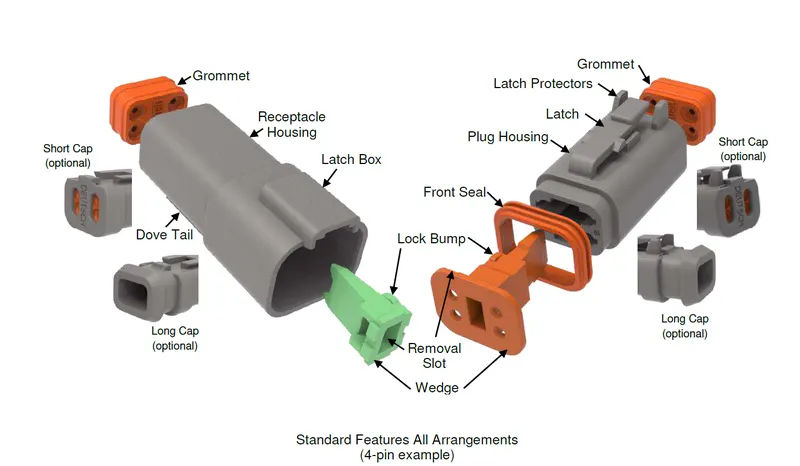
- An electrical connector is an electromechanical device used to join termination and create electric circuits electrical connectors consist of housing, terminals, wedge locks, seals, cavity, mounting cam, etc.,
- A connector basically houses a plastic molded assembly.
- Terminals are connected to the connector.
- A wage lock is a secondary lock, since cavity & mounting clamps
4 Pole connector components:
- Housing.
- Seal.
- Dummy seal.
- Wedge lock.
- Terminals.
Connector selection parameters:
- Electrical connection (Number of Poles).
- Operating current of circuits/wire gauges used
- Packaging space constraints.
- Operating temperature.
- Selling requirements.
- secondary locking requirements
- Required interconnection.
- Application standards.
- Aesthetic/bundle dressing requirements.
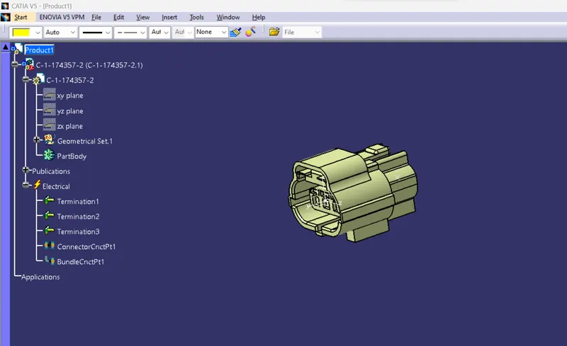
Electrically defines the connector.
To open the Electrical part workbench and select one connector
- create geometrical parameters (point, axis & plane)
- connector connecting point.
- bundle entry point.
- cavity connection point
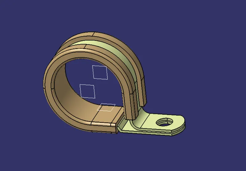
Clips and Clamps
Clips and clamps are holds or external support of the harness bundle for routing from one end to another end without fouling.
Type of clips:
- Simple cable tie.
- Rotation (P-clamp & Furr-Tree clip)and anti-rotational clips.
- Stud-type clip.
- Edge clips.
- Sticky clip.
- Wire-to-wire clips.
Separator Clamps:
Panel Mounted:
- Hole mounted.
- Stud mounted.
- Bolted
- Edge mounted.
- Wire to wire.
Clip selection criteria:
- The selected clip should provide a positive fixing to the harness bundle.
- The clip should be easily available in the market.
- It should be cost-efficient.
- Should be easy to fitment and remove.
- Special tools or techniques should not be required for clip fitment.
- It should fit in the available packaging area.
- Recommended to use anti-rotational clips.
- Dressing and aesthetic considerations.
- Temperature limits and environmental specifications.
Protection:
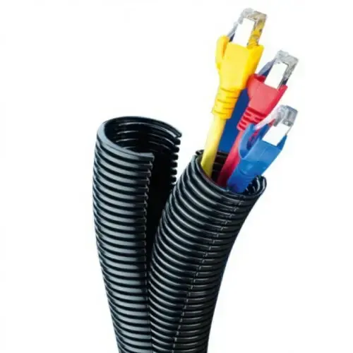
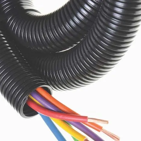
- Corrugated tube convolutes, sleeves, and many other types of coverings are used to protect the wiring harness.
- Graphical representation of coverings are applied on the bundle.
- Following are images of different Coverings.
Types
- Cotton tapping
- Plastic
- Rubber
Selection Parameters:
- Size/Diameters.
- Type of protection devices (Based on Requirement).
- Temperature Range.
- Abrasion Resistance requirements.
- Color Requirements.
- Cost Requirements.
Wire:
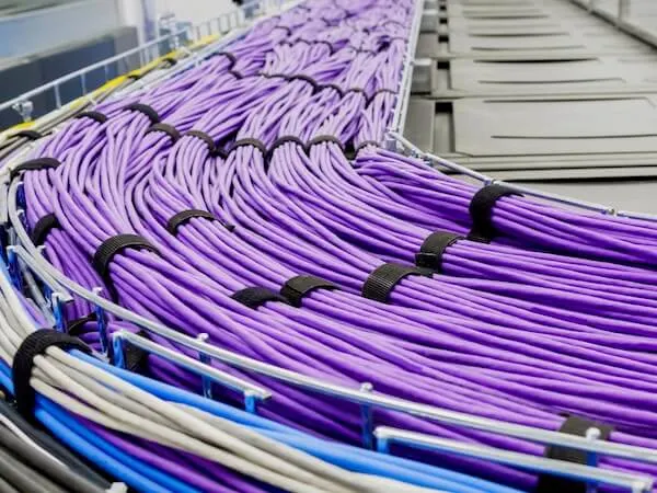
wiring harness consists of various bundled together, with each individual wire responsible for carrying the electric signals and energy used in starting the electrical components in the vehicle.
Wire selection parameters:
- Wire gauge.
- Wire Type/ Insulation Requirments.
- Wire Colour.
- Operating Temperature.
- Flexibility Requirements.
Catalog:
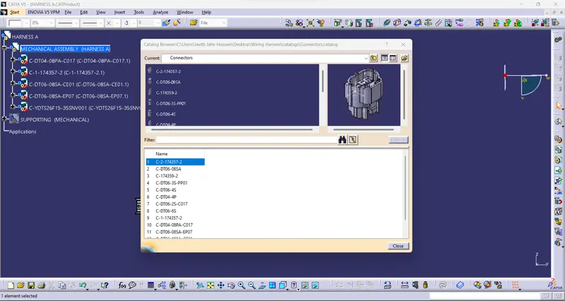
- Adding all connectors into the catalog.
- Then add the required connector to the "Electrical assembly workbench".
- Arrange the connector given the "Engine assembly component".
Design Criteria For Wiring harness:
- Easy to assemble.
- Easy to access for service and maintenance.
- Not get damage in surrounding parts.
- Heat Zone kept away from heat zone.
- Water Splashes kept away from the wet zone.
- Sharp environment kept away from the edge of the panel and sharp corner.
- Human or machine Interaction (HMI).
- Do not route driver and passenger in each zone.
- Kept away from the high-pressure fluid zone.
- Dynamic condition protection.
- Subject to moving parts.
- Not visible and Exposed the harness.
- Easy to access the service and diagnostic.
Clearance management:
- Clearance management basically focused on the wiring harness clearance with the surrounding parts.
- This is a primary requirement for routing and packaging.
- Clearance management should be conducted in CAD software or visualization software.
- It is also known as DMU (Digital Mock Up).
- This study is part of the geometrical interaction.
- Clearance requirements vary from industry to industry. however following requirements can be used to understand the basics of clearance management.
Water Ingress Protection:
- Ingress protection for wiring harnesses mainly deals with connector selection, routing directions, and the use of grommets.
- Vehicle dry zone and wet zone information is a must before you decide on the mechanism, Typically the engine is a wet zone and the cabin is a dry zone it is required to identify doors because door seals create the boundaries.
- Do consider the washing jet pressure standard for the market.
Thermal protection management:
- Harness routing management in the high-temperature zones and the second is additional thermal protection on the harness in case of non-compliance with design guidelines due to technical constraints.
- primary input required to decide the routing path and thermal protection is Thermal mapping data of the vehicle skin temperature data of some hoses are also required if the harness is routed nearby to them.
Harness protection in high-temperature zones:
- Corrugated tubes
Vibration Protection:
- Routing near the sharp edge is one of the major risk factors, which contributes to the rupture of the wiring harness.
- some times we forget to take the dynamic conditions and sharp edges into consideration especially when the harness is mounted on a vibration object. We can also consider taking an alternative routing path to avoid sharp edges or we can use edge protection edge trims, rubber sleeves, grommets, etc.,
- Wiring shall not be routed near screws that can puncture the harness.
- ABC wheel speed sensor cable routing. the wheel speed sensor is mounted on the wheel hub and the cable is routed through shock absorbers which are quite dynamic in operation and creates lot of vibration with high amplitude.
Routing wiring harness using catia
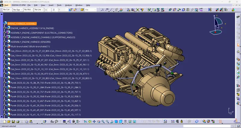
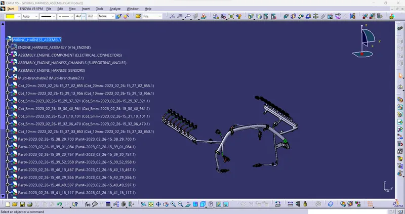
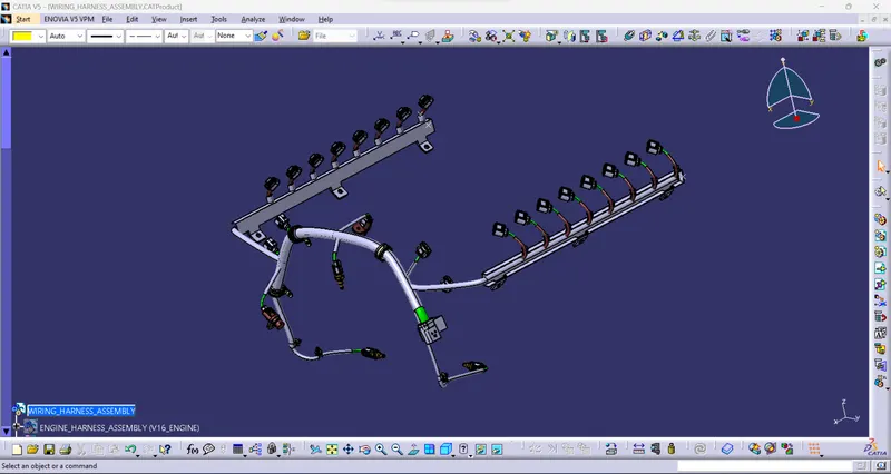
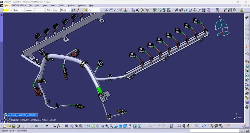
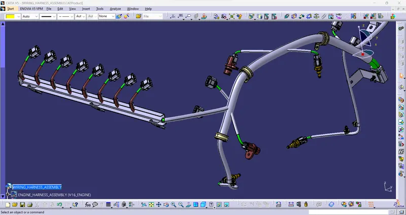
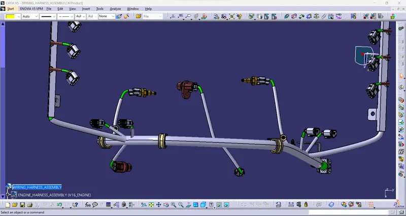
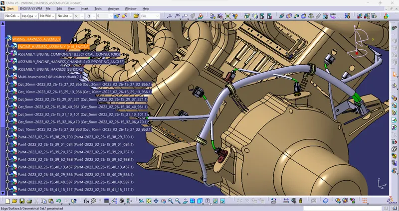
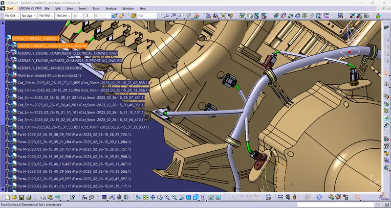
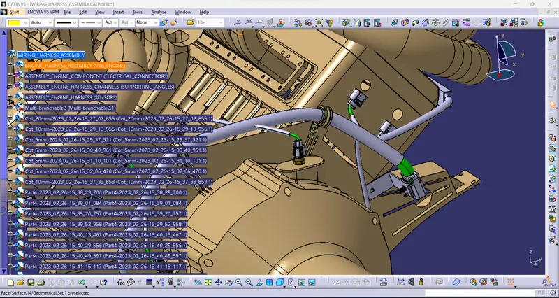
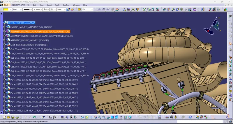
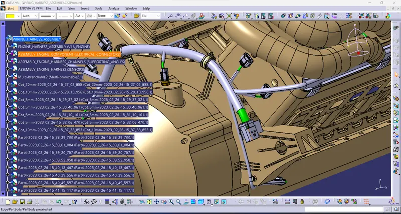
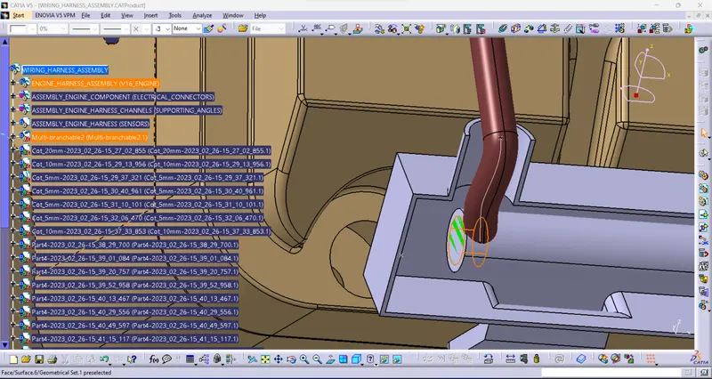
- First, create the harness routing between the given connector and form the V16 Engine.
- Identify the sensors and sparkplug commentator points, camshaft, temperature sensor, etc.,
- Router the bundle based on the bundle routing criteria.
- The engine produces high temperature and vibration, so providing a cot- a tube and cotton tape for insulation.
- Route the bundle to the given components.
- First, arrange and connect the connector in to the sensor and spark plug connector.
- Use the angle and Channel for routing higher temperature zone.
- Use the supporting angle for the interlocking connector.
- Create the branch point and Add the harness using the Bundle geometry.
- Route the bundle using multiple bundle commands.
- Add a branch point to connect the bundle from connector to bundle.
Using connectors:
- 4 pole.
- 3 pole.
- 2 pole.
- sensors.
- clips.
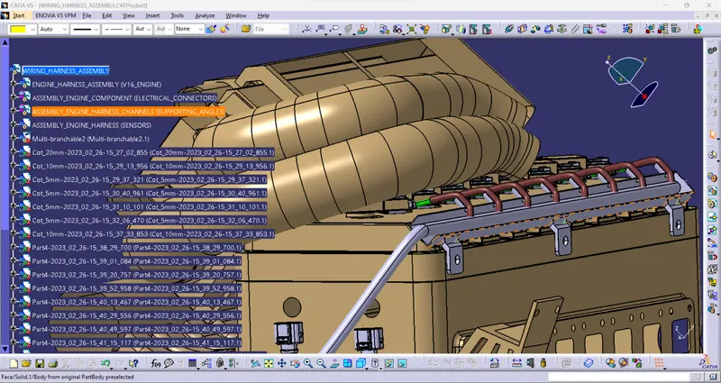
Check Fully connection bundle segment:
- Completely connected to all connectors and bundles.
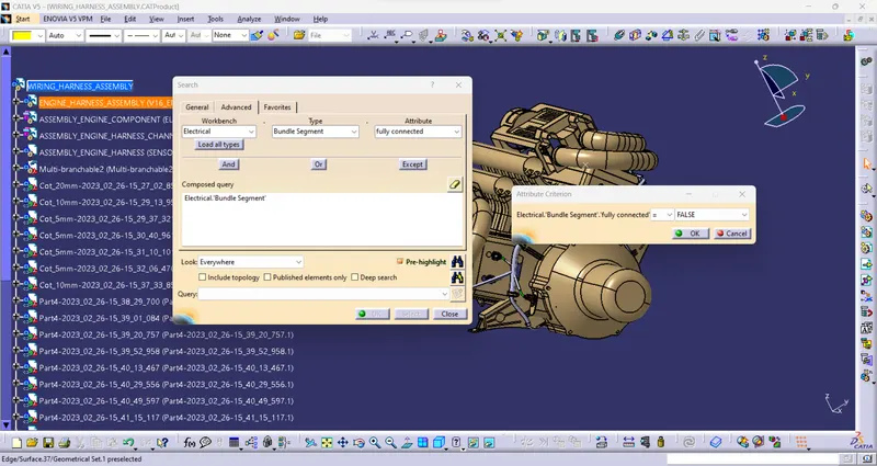
- Check the connector and bundle are completely connected or not.
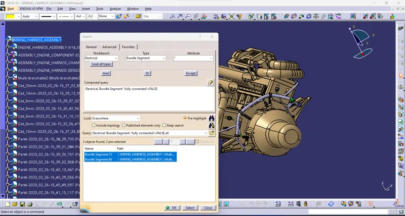
- Using the command "FULLY CONNECTED"
- TRUE= Fully connected bundles.
- FALSE=Not connected bundles.
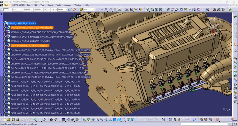
- Show the result.
Electrical Harness Flattening:
- Harness flattening is used to straighten the bundle.
- it is a 3d representation of the bundle routing front view.
- It shows bundle routing information from connector to connector distance and branch point and multiple bundle connection views.
Harness Flattening:
- first, generate the harness flattening parameters.
- Then "Extract" the harness assembly.
- Next, be using the "Flatten" command to select all bundles to flatten the harness.
- To arrange the bundle based on the 3d representation view arrangement.
- To adjust the bundle use the "Rotate" command.
- Using the "Roll" command to rotate the bundle required direction.