Project 1
BOOST CONVERTER
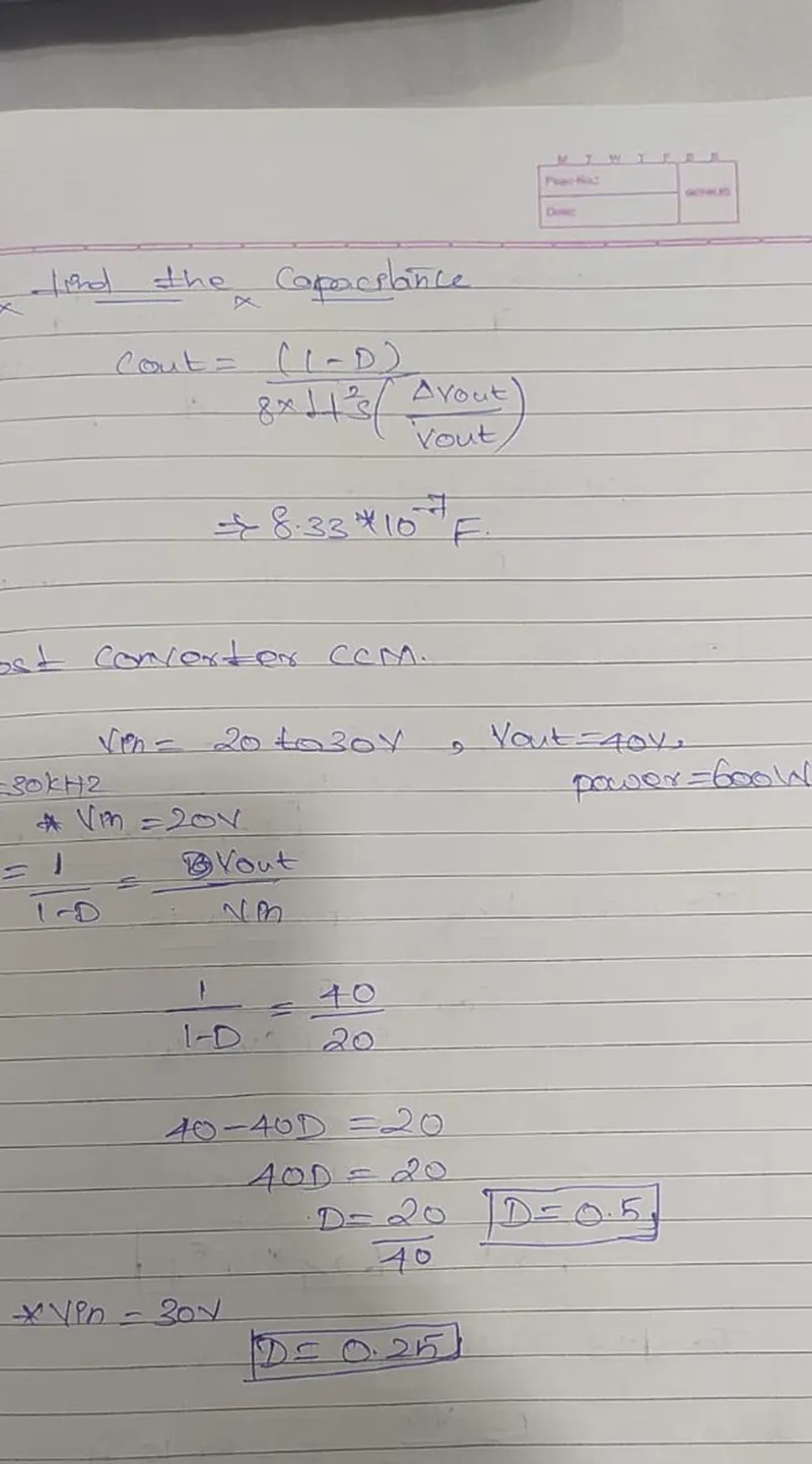
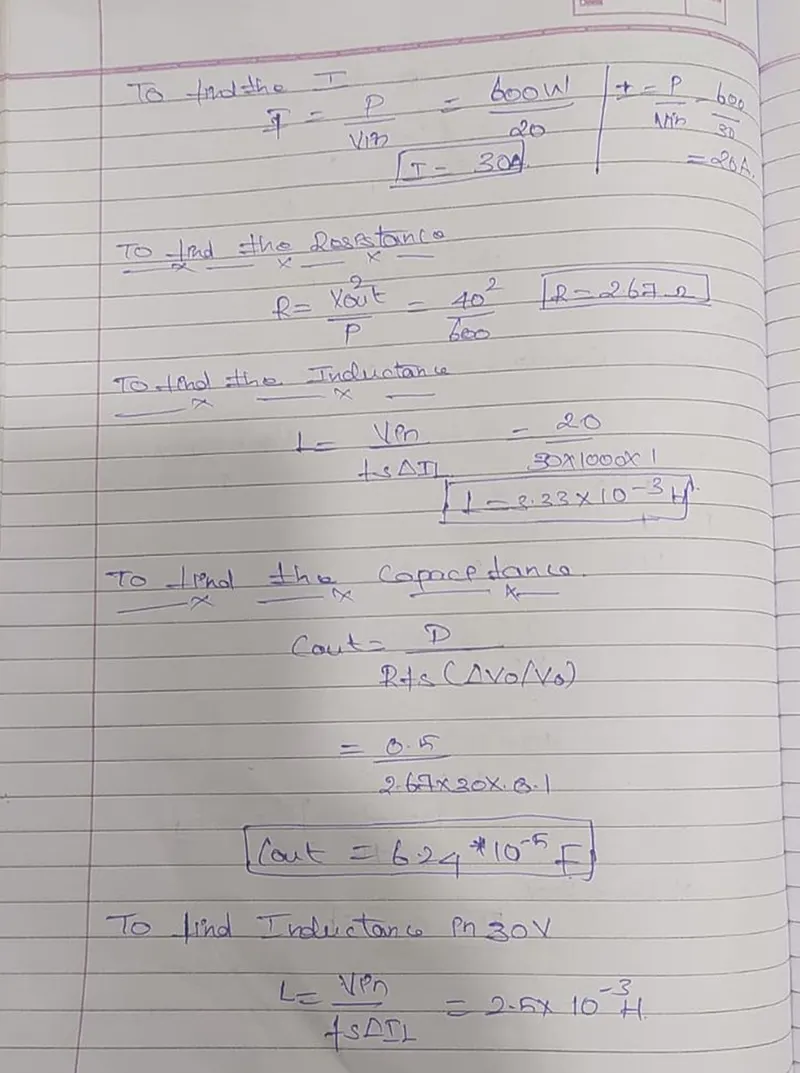
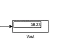
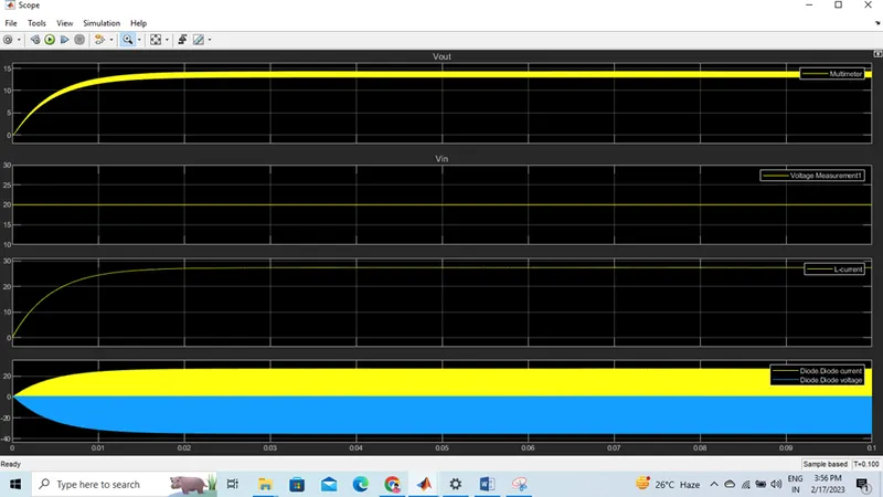
Vin = 20; Vout = 40 ,power = 600W , Fs = 30KHZ ;
D =0.25,R = 2.67 ohm; L = 3.33e-3H ;C =6.24 e-5;
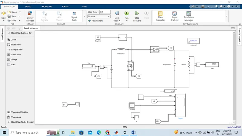
The boost converter is the Step-up DC-DC converter. In the Boost DC-DC converter, the Output capacitor is the one that filters the pulsating current and allows DC current to flow through the output.
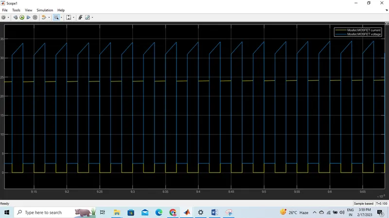
In continuous conduction mode, the inductor current flows continuously during the operation of the converter. The two semiconductor switches in operation are diode and Mosfet which operate with the PWM pulses. MOSFET is a switch whose gate pulses are given by the PWM pulse generator based on the Duty required to the switch.
BOOST CONVERTER
Vin = 20; Vout = 40 ,power = 600W , Fs = 30KHZ ;
D =0.25,R = 2.67 ohm; L = 3.33e-3H ;C =6.24 e-5;
The boost converter is the Step-up DC-DC converter. In the Boost DC-DC converter, the Output capacitor is the one that filters the pulsating current and allows DC current to flow through the output.
In continuous conduction mode, the inductor current flows continuously during the operation of the converter. The two semiconductor switches in operation are diode and Mosfet which operate with the PWM pulses. MOSFET is a switch whose gate pulses are given by the PWM pulse generator based on the Duty required to the switch.
BLOCK DIAGRAMS
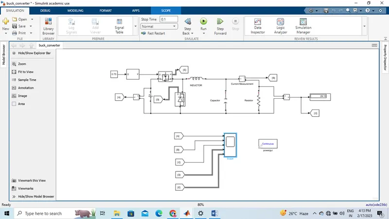
BUCK CONVERTER
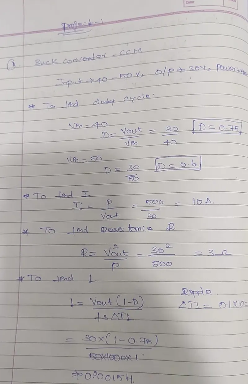
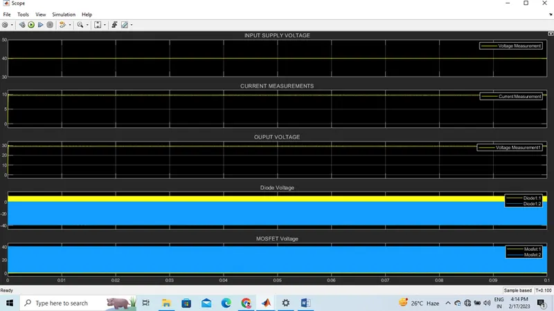
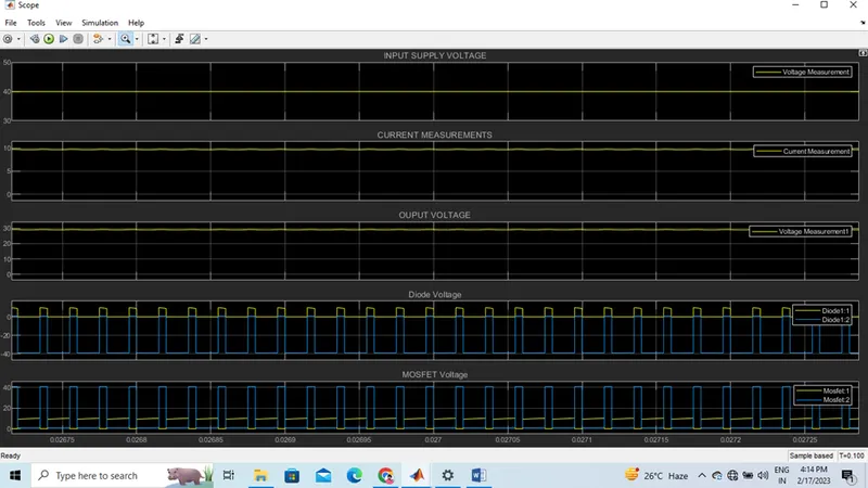
Vin =40 ; Vout = 30 V ; power =500W
D = 0.75 ; I =10 a ; R= 3 ohm; L = 0.00015 H ; c = 8.33 e-7 F;
Buck converter steps down the DC voltage. It consists of Inductor, Capacitor, and two switches which are Transistor and diode. Transistor (MOSFET or IGBT based on the application) is a switch that operates with On and Off states. ON and Off states of switch get controlled by the Gate signal.
BLOCK DIAGRAM
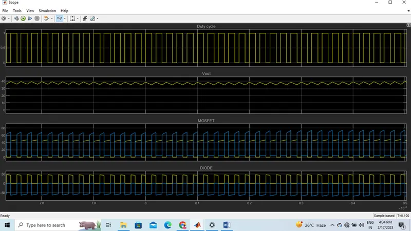
OUTPUT:
SEPIC
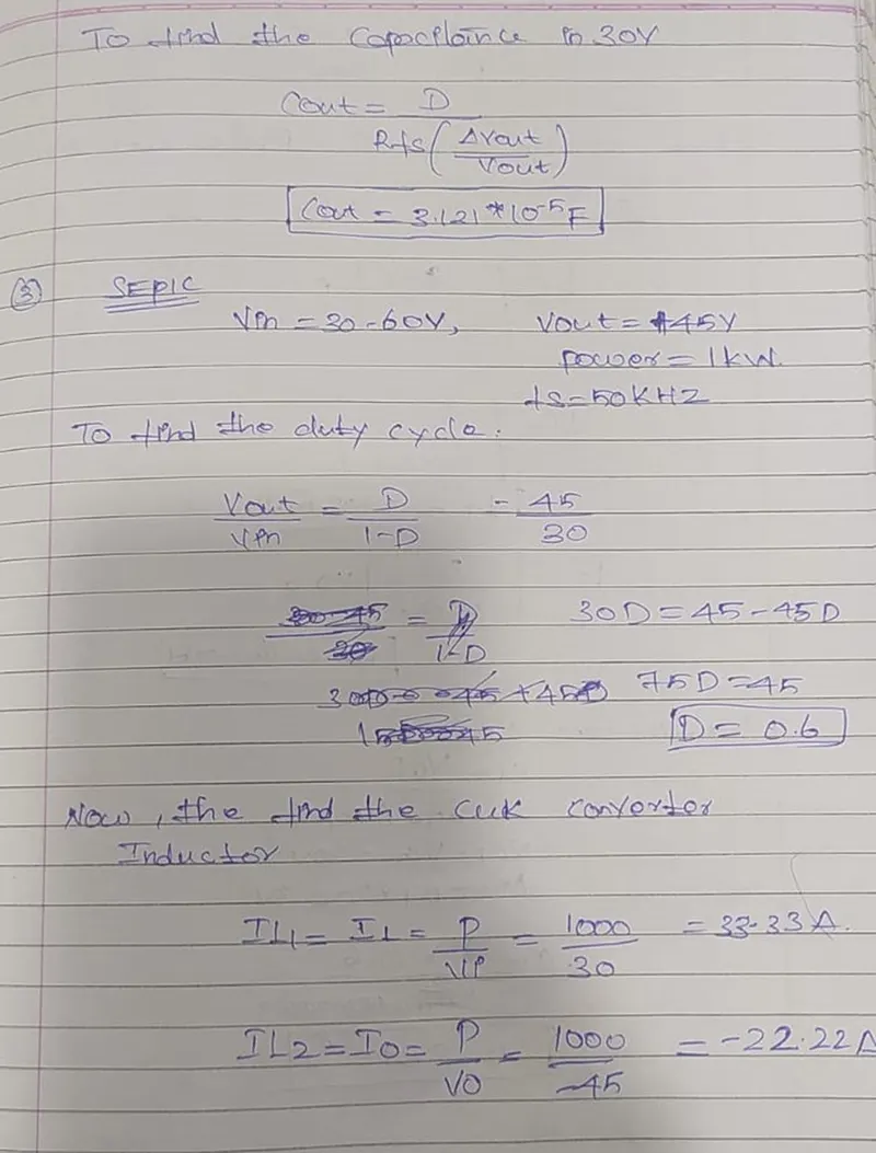
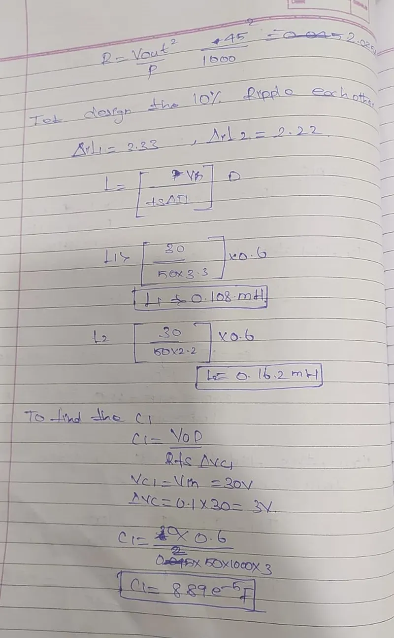
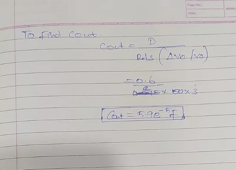
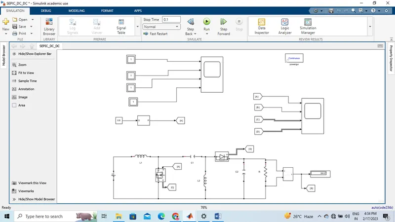
Sepic Converter is the Single Ended Primary inductor converter. This is a type of DC-DC Converter that operates to allow the electrical output is greater than, less than, or Equal to the input. Output is controlled by the duty cycle of the control switch.
MODEL
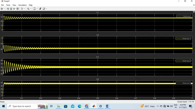
OUTPUT