Final Project: Electric Rickshaw modelling
FINAL REPORT
ABSTRACT:
In this project, we work to create the MATLAB model of the ELECTRIC RICKHAEW by doing a PM brushed type DC motor and a suitable Lithium-Ion battery for the motor. Before this, we will remember what is Electric RICKHAEW, how it's functioning and the privileges of EV RICKHAE Then we make an actual EV RICKHAEW model in SIMULINK with suitable blocks from the powertrain block set. My main motto is to examine "how my RICKHAEW performs for any three standard driving cycles showing energy consumption, the temperature rise of motor and controller for vehicle cover around 100 km at constant speed driving 45 Kmph. Made a comparison with Mahindra E-Rickshaw and my Simulink model.
OBJECTIVES:
Create a detailed MATLAB model of an electric rickshaw (three-wheel passenger vehicle) as per the details below:
- Rear wheels driven by PM brushed type motor
- Assume efficiency points of motor controller and motor
- Make an excel sheet of all input and assumed data
- Results: For any three standard driving cycles show energy consumption, the temperature rise of the motor and controller for 100 km constant speed driving at 45 kmph.
METHODOLOGY:
- The electric vehicle consists of a battery, motors, and controller then it generates propulsion power.
- To design any vehicle 1st we have to calculate propulsion power then the motor is selected.
- Lastly based on the motor rating or operating range and no km/charge we want to depend on everything battery capacity and then battery capacity is selected.
So the Design flow of the vehicle engineers has to be like the following:
- Identify what amount of propulsion power is required.
- What is the best suitable motor for that propulsion power?
- Then type of battery and range of battery according to the range.
INTRODUCTION:
- Electric E-Rickshaw is also known as an electric tuk-tuk, e-rickshaw and auto which are going more popular after 2018 in the Indian market. This E-rickshaw is the best alternative to petrol/CNG auto-rickshaw and human or horse-pulled rickshaws because of their low fuel cost, zero emissions and less human efforts.
- The electrical system used in the Indian version is 48VDC can run 90-100 km/full charge, top speed 25 km/hour and this electric motor power ranging from 650-1400 Watts: the battery takes 8-10 hrs to become fully charged. Basic seating capacity is driver plus 4 passengers total of 5 persons
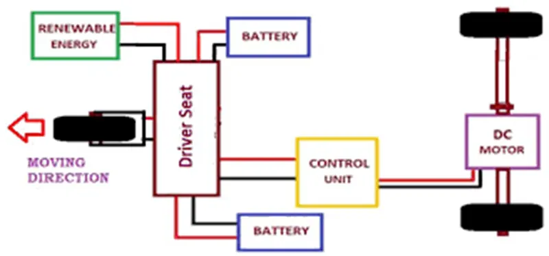 .
- Here basically, e-rickshaw is designed in CREO and MATLAB Simulink In the designed electric rickshaw main blocks are battery, drive cycle, controlled, DC Motor, Vehicle body and transmission system. Drive cycle is the input of human effort that how he is going to drive his actual cycle We can use dive cycle like FTP75, WOT or by using Excel
- The main objective of this project is to obtain speed by the driver, to estimate the temperature of the motor and controller, to estimate the state of charge (SOC) and distance travel by the vehicle. There is a SOC block that will estimate the state of charge of the battery, distance is calculated by speed and time parameter for all the three Drive cycle
Design and Construction:
These rickshaws have an MS(Mild Steel) tubular chassis consisting of three wheels with a differential mechanism at the rear wheels. The motor is a brushless DC motor manufactured mostly in India and China. The electrical system used in the Indian version is 48V and in Bangladesh is 60V The body design from the most popular Chinese version is of very thin iron or aluminium sheets. Vehicles made in fibre are also popular because of their strength and durability, resulting in low maintenance, especially in India.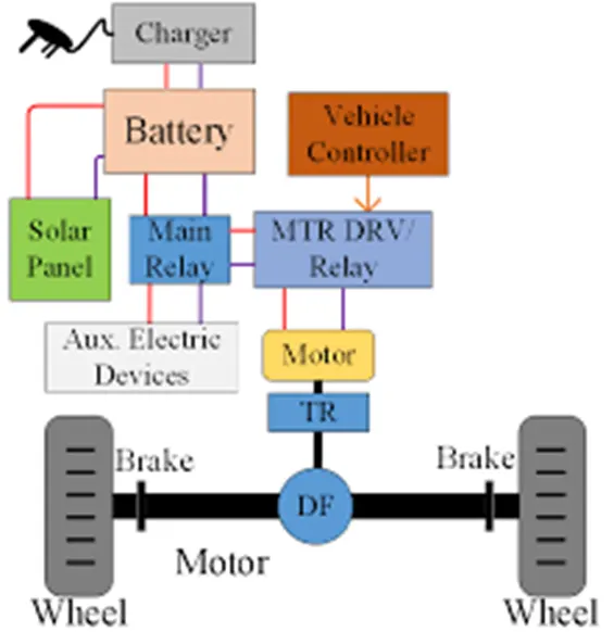
- The body design is varied from load carriers, passenger vehicles with no roof, to full body with windshield for drivers comfort. It consists of a controller unit. They are sold on the basis of voltage supplied and current output, also the number of MOSFET (metal oxide field-effect transistors) used. The battery used is mostly a lead-acid battery with a life of 6-12 months. Deep cycle batteries designed for electric vehicles are rarely used. The weight of the electric car has also been a recurring design difficulty in them.
Important Simulink Block used in Electric Vehicle design are:
- Drive Cycle Source
- Constant
- Longitudinal Drive
- Controlled Voltage Source
- Controlled PWM Voltage
- Solver Configuration
- Electrical Reference
- H-Bridge
- DC Motor
- Mechanical Rotational Reference
- Current Sensor
- Battery
- Controlled current source
- PS-Simulink Converter
- Vehicle Body
- Tire
- Simple Gear
- Inertia:
- PS Constant
- Gain
- Integrator
- Divide
- Display
- Scope
OVER_ALL_BLOCK_DIAGRAM
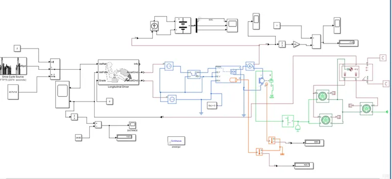
- Vehicle body and tire :-
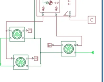
- Represents a two-axle vehicle body in motion.
- Accounts for body mass, aerodynamic drag. grade, externally defined mass and centre of gravity of the vehicle body.
o Input Ports:
W=Wind Velocity in m/s
beta=Grade angle in radians
o Output Ports:
V=Velocity in m/s
NR=Normal force on Rear Axle (N)
NF=Normal Force on Front Axle (N)
Vehicle Body Parameters:
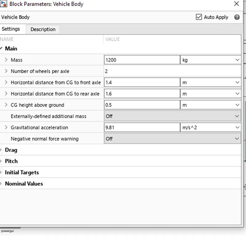
- Vehicle body mass, Centre of gravity distance values and aerodynamic drag
variables are modified. Pitch dynamics are kept ON with other variable values as default values.
1.1Tire: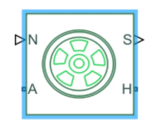
The vehicle is assumed to be front axle is driven (4 wheels- 2 on each axle).
The wheels are modelled using simple Tire (Magic formula) Simulink blocks.
The block can model tire dynamics under constant or variable contact surface
conditions.
- Input Port:
N=Normal force acting on the tire, positive when force is acting downwards/towards the contact surface.
- Output Port:
S=Slip value is relative to tire and surface of contact.
- Conserving Ports:
H=represents wheel hub which transmits thrust generated by the wheel to the body of the vehicle.
A=represents the axle on which the tires are mounted.
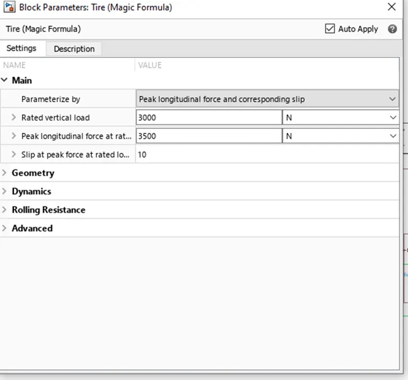
- The tires are parameterized by Peak longitudinal force and corresponding slip
- The other block parameters such as rated vertical load, peak longitudinal force at rated load and slip at peak force at rated load - are kept with their default values.
1.2 Gear: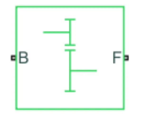
A simple gear block is used to connect the motor to the rear axle of the vehicle.
It represents the gearbox that connects the input shaft to the base gear and output from the follower gear.
Conserving Ports:
B=port associated with an input shaft (motor shaft)
F=port associated with the output shaft (axle/ differential)
Simple Gear Parameters:
Gear ratio and output direction are modified. Meshing loss is kept constant and gear is having a constant efficiency throughout the simulation.
Viscous losses and faults are kept at default conditions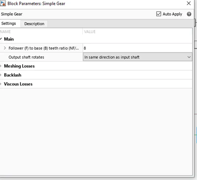
1.3 Vehicle Body:-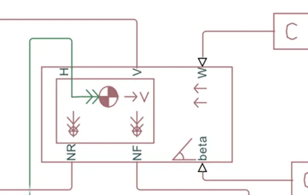
- This block basically represents a two-axle vehicle body in longitudinal motion. The block accounts for - body mass, aerodynamic drag, road incline, weight distribution between axles due to acceleration road profile.
- Here, connection H is the mechanical translational conserving port hub.
- NF & NR correspond to the output ports for normal reaction forces on the front axle and rear axle wheels respectively.
- Connection V represents the actual output translational velocity of the vehicle.
- beta is the road inclination angle & W corresponds to the headwind speed (headwind direction opposite to that of the vehicle).
- The gross weight is given to be 1000 kg
- The geometric parameters of the vehicle are given as -
- Power and Motor Controlled Subsystem:-
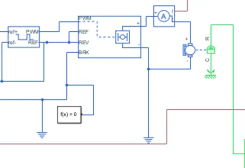
2.1 H-Bridge:-
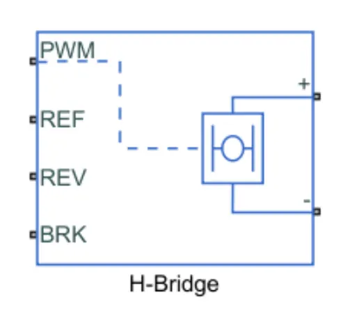
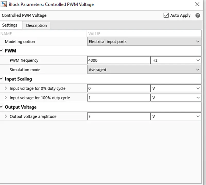
The H-Bridge helps in controlling the power that is input according to the requirement. The output provided is converted voltage as per the controlled parameters.
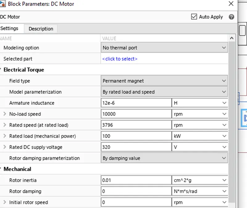
2.2 D.C Motor:-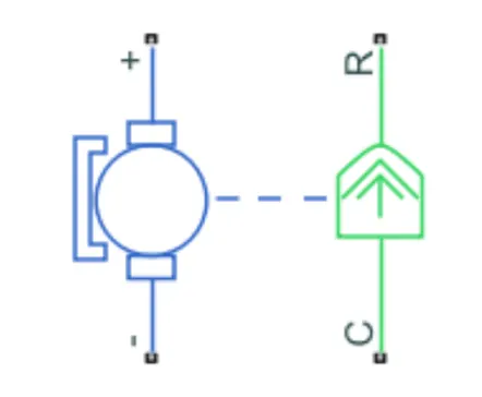
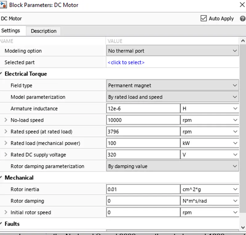
This is the DC Motor which would give rotational power to the wheels and become the sole power generation source.
The DC Motors terminals are connected as mentioned below.
+ =Electrical signal to the motor Positive Terminal
- =Electrical signal to the motor Negative Terminal
R=Casing of the Motor connected with the Mechanical Rotational Reference Block
C=Rotor Case connected to the Mechanical Rotational reference
The parameter considered is, The Armature inductance is as default, varied the changes in the No-Load Speed 3000 rpm, the rated speed 1800 rpm, the Rated Load at 2kW, and the Rated DC Supply Voltage 29 V. All other parameters are as default.
2.3 Controlled PWM Voltage: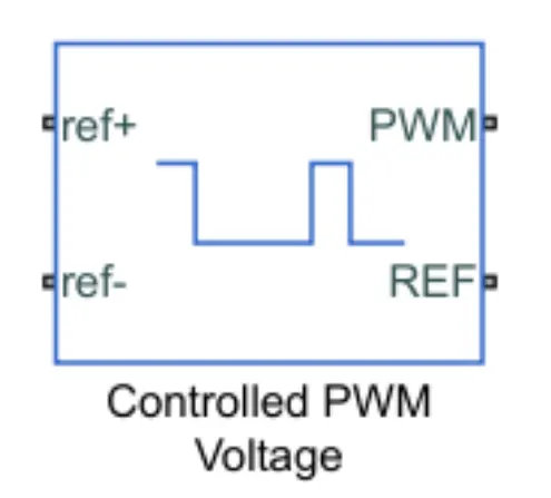
The Controlled PWM Voltage Block helps in keeping the Modulated Pulses as per the required pulses. So that the operations happen smooth and higher variations are not observed.
The Ports are connected as follows.
PWM=PWM connected directly to the H-Block
REF=REF connected directly to the H-Block
ref+ = Reference Positive connected with Driver Model ith the Acceleration Commands from the
ref- =Reference Negative connected with the Deceleration Commands from the Driver Model
Note: The parameters are set as default.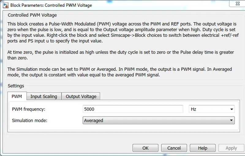
3 Battery and SOC System:-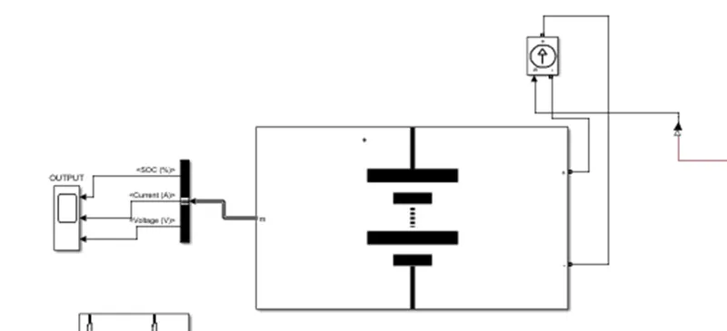
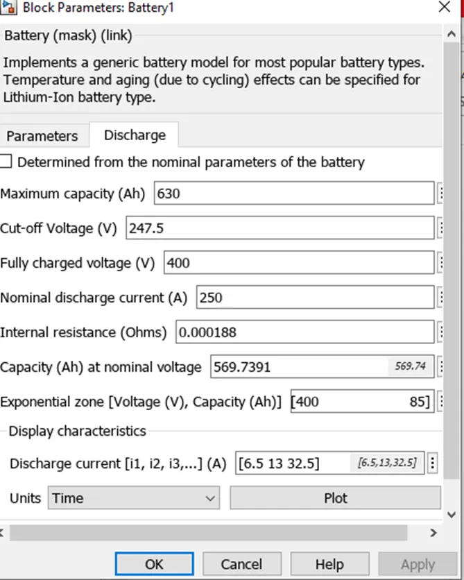
3.1 Battery:-
Implements a generic battery model for most popular battery types. Temperature and ageing (due to cycling) effects can be specified for Lithium-Ion battery type.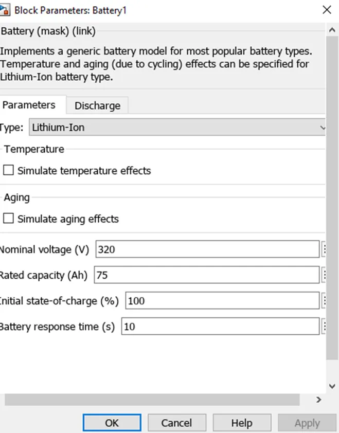
3.2 controlled Current Source:- 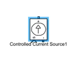
a controlled current source is connected to the lithium battery. this controlled current source provided will initiate the flow of current from the battery to the motor and during regenerative braking from the motor to the battery.
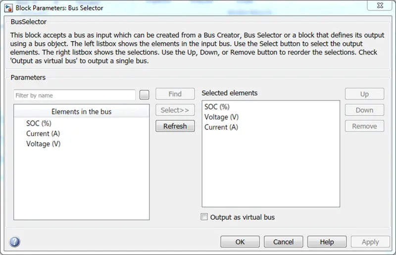
3.3 Bus selector
4 Longitudinal Driver: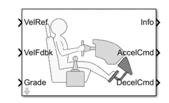
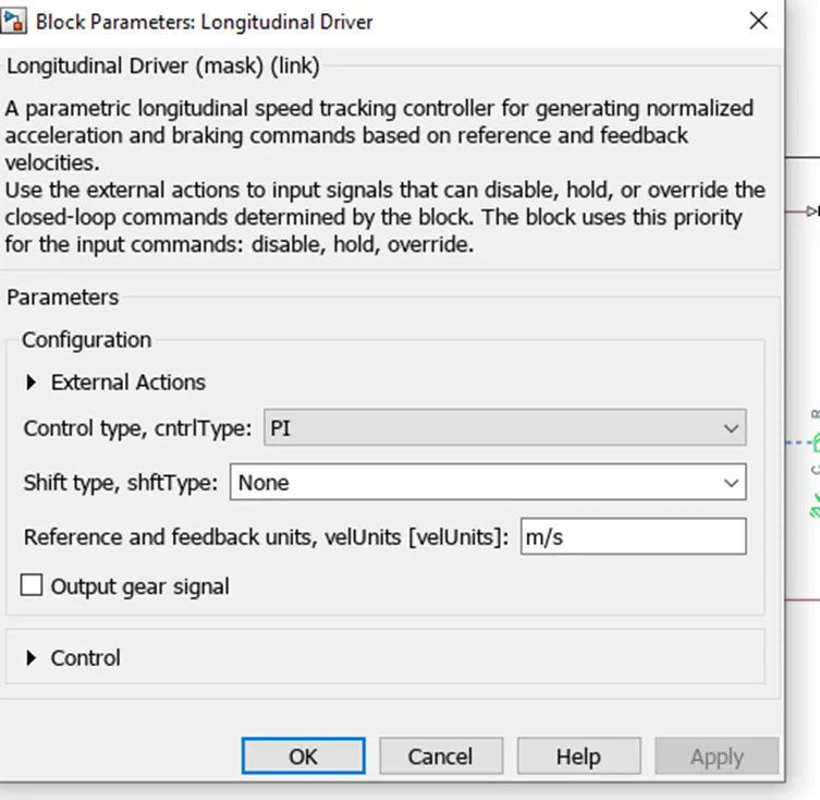
- Longitudinal Driver is an inbuilt block provided by the powertrain blocks.
- It is a parametric longitudinal speed tracking controller for generating normalized Acceleration and Braking commands based on reference and feedback velocities,
- The VelFdbk port corresponds to the feedback velocity. The actual velocity output given by the vehicle body is connected here. By comparing the actual (feedback) velocity with the reference velocity, the driver block generates acceleration and braking signals in order to minimise the error between the two concerned velocities.
- Grade corresponds to the grade angle. For this simulation, no inclination is considered and hence, a constant block with value 0 is connected.
- Info gives the output for the bus signal for different block calculations like the difference in reference vehicle speed and vehicle speed, etc.
- AccelCmd & DecelCmd correspond to the acceleration and deceleration commands generated respectively and are connected to the corresponding ports of the Controlled PWM Voltage block Here, the selected control type is Pl. Accordingly, the block implements proportional-integral (PI) control with tracking windup and feed-forward gains.
5 Reference Velocity (Drive Cycle):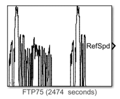
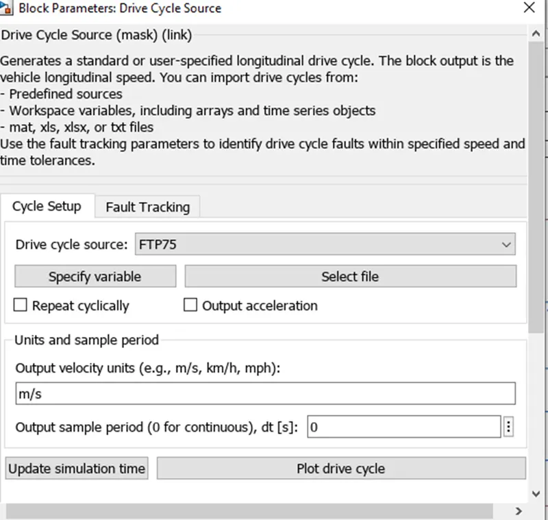
- The Drive Cycle Source block is used to provide the reference speed for the simulation.
- It generates a standard or user-specified longitudinal drive cycle.
in this selected driving cycle is FTP75
this is the plot of the FTP75 drive cycle 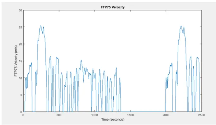
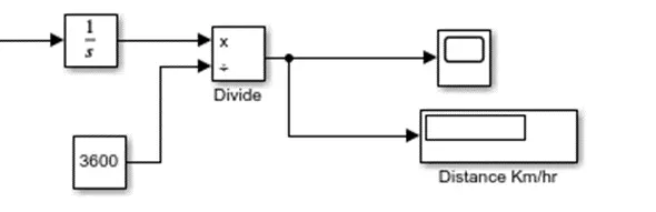
7 Distance in km/hr
The scope will display velocity of the vehicle in km/hr to measure the distance in km, an integrator block is used because the interaction of velocity will give us distance and 3600 constant blocks are used because 1hr=3600sec
8 Simulink Explanation:-
The system is running for simulation for 28850 s which is the total time for which the input drive cycle is defined.
A Solver Configuration is added to ensure proper solving of the mathematical equations by the model.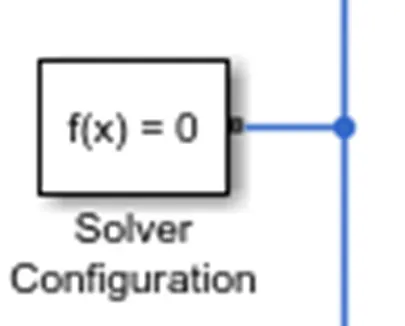
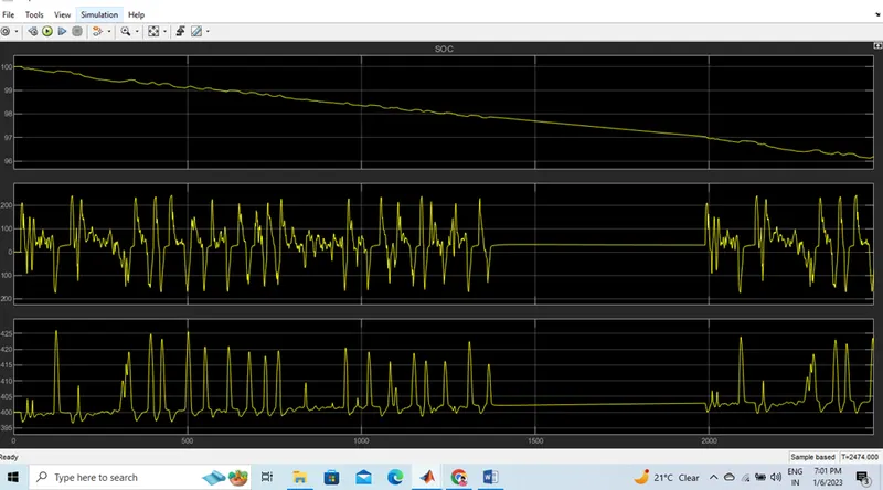
- Scopes are connected to analyze different outputs such as the SOC of the battery, the reference velocity & the actual velocity of the vehicle and the distance covered by the vehicle during the total run
RESULTS:-
1)INPUT AND OUTPUT DRIVE CYCLE FTP 57 DRVE CYCLE
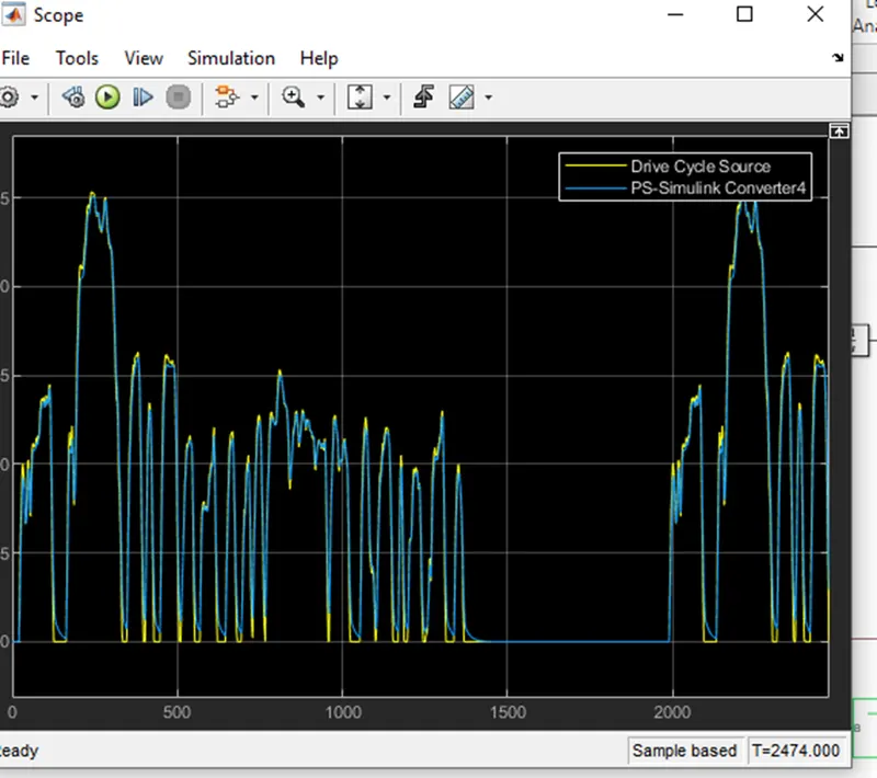
The blue line is a graph of the drive cycle source and the yellow line shows the corresponding velocity graph
2) Distance Covered IN 45 KM SPEED
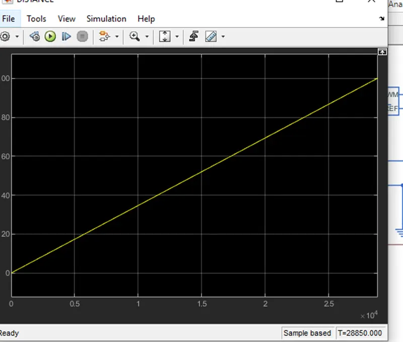
the yellow line shows the distance covered by the electrical car
3) SOC calculation FTP 57 DRVE CYCLE:
- the change of SOC
- the change of battery voltage
- the change of battery current
CONCLUSION:
from the above model and from the assumed parameters we found that the velocity of an electric vehicle is 100 KM in 28850 in sec