Project 1
PROJECT
1. Design a battery pack for a car roughly 150 Kw with 120 V. Use 3500 mAh 3.6V nominal NMC chemistry cell.
a. Design the battery pack configuration.
b. Draw the BMS topology for this battery pack.
AIM - Design the battery pack configuration ,Draw the BMS topology for this battery pack using given data and also Build 3s2p battary pack configaration by using the MATLAB/SIMULINK tool.
Theory -
Battery Management System -
A Battery management system(BMS) is said to be the brain of a battery pack. The BMS is a set of electronics that monitors and manages all of the battery’s performance. Most importantly, it keeps the battery from operating outside of its safety margins.
The primary function of the BMS is to protect the battery cells from damage caused by being overcharged or over-discharged. Additionally, the BMS calculates the remaining charge, monitors the battery’s temperature, monitors the battery’s health and safety by checking for loose connections and internal shorts.
The BMS also balances the charge across the cells to keep each cell functioning at maximum capacity.
Given,
Nominal voltage = 3.6V
Cell capacity = 3500mAh = 3.5Ah
Power= 150KW
Rated voltage = 120V
Battery Current= Power/Voltage
= 150000/120
= 1250 A
Number of Cells in Series -
No. of cells in series= Rated battery voltage/Nominal cell voltage
= 120/3.6
= 33.3
Case 1: Rounding off 33.3 to 33
Nominal battery voltage= Cell nominal voltage*33
= 3.6*33 = 118.8 V
Maximum battery voltage= Cell maximum voltage*33
= 4.2*33 = 138.6 V
Minimum battery voltage= Cell minimum voltage*33
= 2.7*33 = 89.1 V
Case 2: Rounding off 33.3 to 34
Nominal battery voltage= Cell nominal voltage*34
= 3.6*34 = 122.4 V
Maximum battery voltage= Cell maximum voltage*34
= 4.2*34 = 142.8 V
Minimum battery voltage= Cell minimum voltage*34
= 2.7*34 = 91.8 V
Table shown the above Case 1 and Case 2 results.
| Sr No | Number of Cells in Series | Nominal Voltage | Max Voltage | Min Voltage | Required Voltage |
| Case 1 | 33 | 118.8V | 138.6V | 89.1V | 120V |
| Case 2 | 34 | 122.4 | 142.8 | 91.8V | 120V |
The condition to choose the number of cells are
- Max Voltage of battery should be less than the Load Max Voltage
- Min Voltage of battery should be greater than the Load min Voltage
It is better to have Nominal Voltage Greater than Required Voltage so selecting Case 2
So, Number of Cells in Series = 34
Output Voltage = 122.4V
Number of Cells in Parallel -
No. of cells in parallel= Total current/Cell capacity
= 1250/3.5
= 357.4
Rounding off to Higher Number, No. of cells in parallel is taken as 358
The battery pack configuration is 34s358p
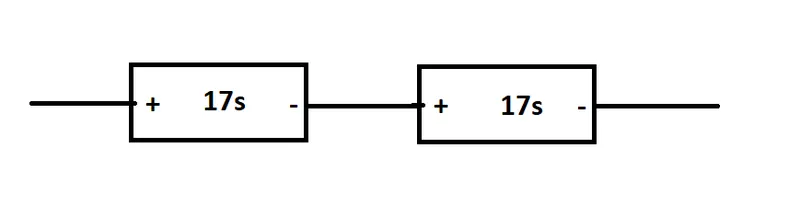
The 34 cells are connected in series like shown below
b. BMS Topology for Battery Pack -
Since Cells in Series = 34
Cells in Parallel = 358
Total No of Cells = Number of Cells in Series * Number of Cells in Parallel
= 34 * 358
Total No of Cells = 12172
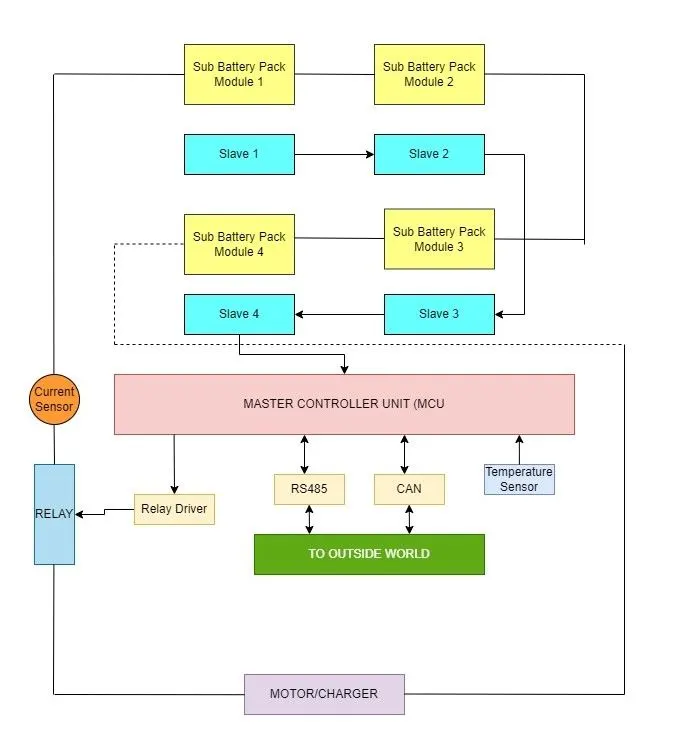
Cells are divided such that each Module will 17Cells in series and 179 Cells in Parallel so 1 module will consist of 3043 Cells. So 4 Such Modules will be required to form a Battery Pack with 122.4V.
Master and Slave Topology is selected for this Battery Pack configuration. Master and Slave Bms can handle more than 18 no of cells in series. So for above battery pack there will be 4 slaves and 1 Master MCU. Slaves wil collect data of its own module and give to other slave and that slave with its own module data with the previous module data will give to another Slave and the last slave will give all the data of 4 slaves to Master MCU. All the Slave will have 1 Analog Front End(AFE). Master and Slave have Scalability since more no of slaves can be added.
Below picture shows the Master and Slave BMS Topology.
2. Build a 3S2P battery pack configuration with generic battery block using Matlab/Simulink.
Procedure -
To Build 3S2P Battery Pack Configuration
Number of Cells in Series = 3
Number of Cells in Parallel = 2
Total Number of cells in Battery Pack = No. of cells in series * No. of cells in parallel
= 3 * 2
= 6
Total Number of cells in Battery Pack = 6 Cells
Step 1:
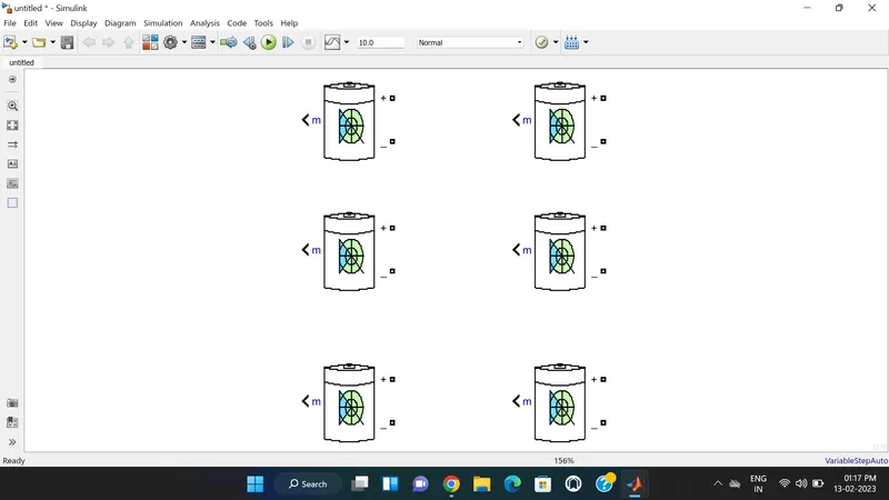
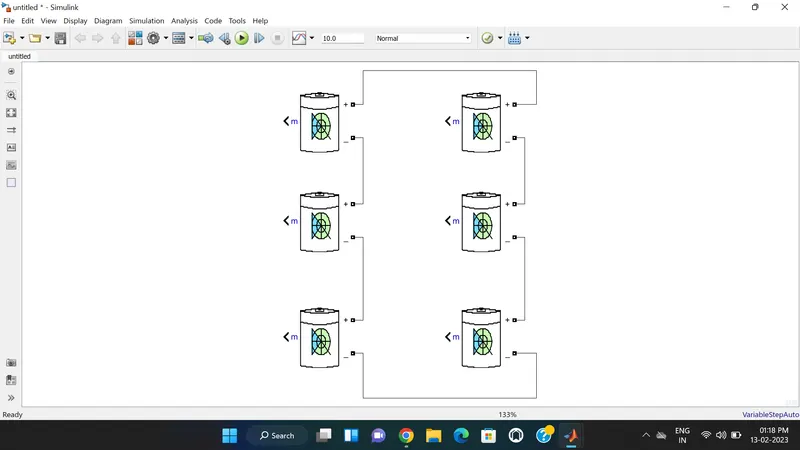
Arrangement of 6 cells. The Below figure shows 6 cells arranged to create a battery pack.
Step 2: Connecting Cells in Series
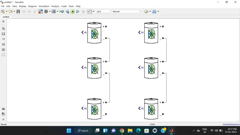
The figure below shows the battery connected in series and parallel combination. Batteries are connected from terminal to terminal in a way that the positive (+) terminal of one battery is connected with the negative (-) terminal of the other battery and negative terminal (-) of one battery is connected with the positive terminal (+) of the other battery.
Step 3: Connecting Cells is Parallel
The below figure shows the cells connected in parallel. For parallel connection, batteries are connected from terminals to same terminals of other batteries that is positive terminal (+) of one battery is connected with positive (+) terminal of other battery and negative terminal (-) of one battery with negative terminal (-) of other battery.
SIMULINK MODEL -
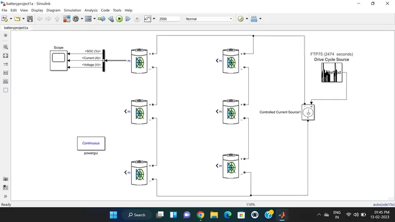
The scope output used for the battery pack consists of SOC (State of Charge), Current and Voltage. The controlled current source shows the direction of discharging current flow from Battery to Load. Drive cycle is applied to the Controlled current source which clearly shows the results according to the vehicle performance.We used the FTP75 drive cycle whose cycle time is 2474sec so, we selected 2500sec as the simulation time.
The parameter given inside the battery is given below:-
- Nominal voltage of a cell 7.2V
- Rated capacity of a cell 5.4Ah
- Maximum voltage of a cell 8.3807V
Nominal Voltage of the Battery Pack = No.of cell in series * Nominal voltage of a cell
= 3 * 7.2
= 21.6V
Nominal Voltage of the Battery Pack = 21.6V
Rated Capacity of the Battery Pack = No.of cell in Parallel* Rated Capacity of a Cell
= 2 * 5.4
= 10.8Ah
Rated Capacity of the Battery Pack = 10.8Ah
The Battery Pack Rating is 21.6V, 10.8Ah ,233.28Wh
Maximum Voltage of Battery Pack = Maximum Voltage of Cell * No. of Cells in Series
= 8.3807 * 3
= 25.14V
RESULTS -
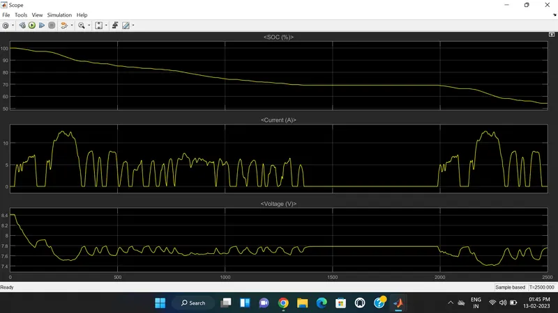
As the distance covered by the vehicle increases the Battery SOC gets reduced.when battery is fully charged is value is 100% then is starts decreasing as it covered the distanced. After 2500 sec it reduced to nearly 55%.
When the vehicle is in rest then no current flow through the battery and when it starts, the current get increased and decreased according to drive cycle shown in the above Current Plot.
The rated capacity of cell is 8.3807V is shown in the above voltage plot. As the vehicle covered the distance according to drive cycle the voltage of the cell get decreases which is clearly seen in above result.
CONCLUSION -
In this Project we understood that how to designed the Battery Pack for a car with 150KW 120V by using 3.6V 3.5Ah NMC Cell and BMS Topology is also selected for the Battery Pack. Also we created A 3S2P battery pack configuration with generic battery block using Matlab/Simulink.