Project 1
Aim:
Project 1
Objective:
- Design a battery pack for a car roughly 150 Kw with 120 V. Use 3500 mAh 3.6V nominal NMC chemistry cell.
- Design the battery pack configuration.
- Draw the BMS topology for this battery pack.
- Build a 3S2P battery pack configuration with generic battery block using MATLAB/Simulink.
Objective 1:
Design a battery pack for a car roughly 150 Kw with 120V. Use 3500 mAh 3.6V nominal NMC chemistry cell.
- Design the battery pack configuration.
- Draw the BMS topology for this battery pack.
Theory:
Given data:
Battery power capacity = 150Kw
Battery voltage capacity = 120V
Battery capacity = 3500 mAh
Nominal cell voltage = 3.6V
a. For designing the battery pack:
P = V*I
I = P/V = 150*10^3/120 = 1252 A
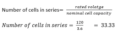
Cells in series:
Number of cells in series
Case A & B:
We haven’t given any maximum voltage capacity of battery
For case A we have 33 cells:
Nominal cell capacity = 33×3.6 = 118.80 V
For case B we have 34 cells:
Nominal cell capacity = 34×3.6 = 122.40 V
Here, we can use 33 cells in series which is under nominal capacity of battery.
Cells in parallel:
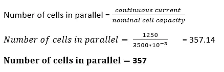
Battery configuration is 33S357P.
b. Draw the BMS topology for this battery pack.
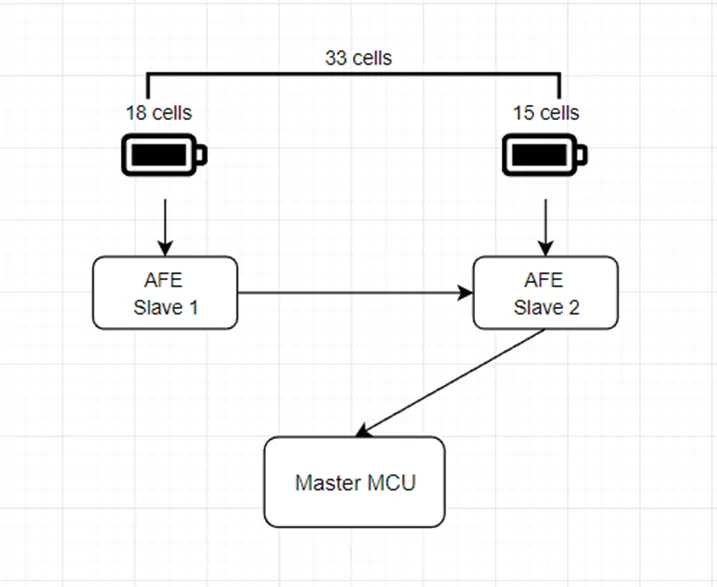
Here, we are using Master Slave Architecture.
Here, we have 33 number of cells.
For each we can connect maximum of 18 cell.
Here we can connect 18 & 15 cells.
File reference:
https://drive.google.com/file/d/1CvO9twyFgyOhK8Jub82lcJBbtVOseIQQ/view?usp=share_link
Refer to Master Slave Topology shown in the video:

Objective 2:
Build a 3S2P battery pack configuration with generic battery block using MATLAB/Simulink.
Theory:
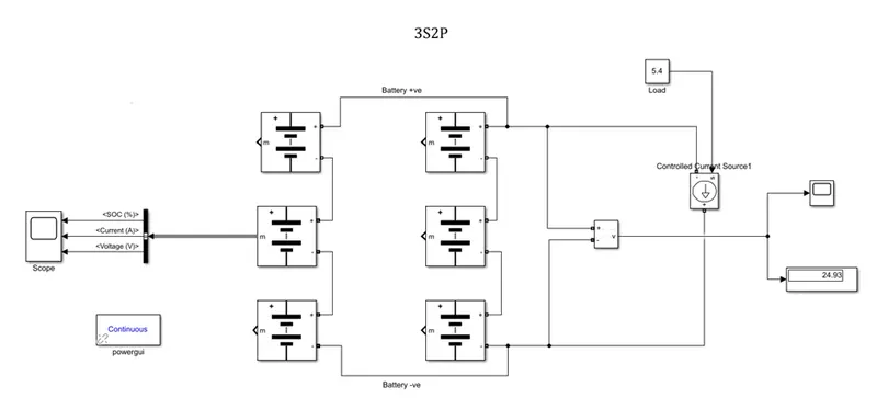
Here in this objective, we are designing a battery pack with configuration 3S2P.
Components:
- Battery packs
- Voltage sensor
- Controlled current source
- Bus operator
- Scopes
- Display
- Constant
- Continuous block
Steps to be followed:
- Take a simple battery.
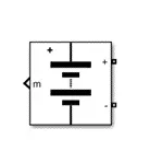
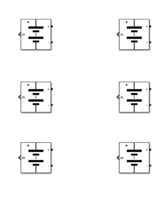
- Copy the above blocks make 6 blocks.
Arrange the battery block as given below.
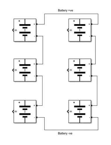
3. For series connection, we are connecting the battery +ve to next battery -ve (different terminal) and vice versa.
For parallel connection, we are connecting the battery +ve to the battery +ve(same terminal) and vice versa.
The given configuration is 3S2P
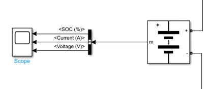
4. Connect the Battery to Bus and Bus to Battery.
5. Connect the Voltage measurement block to battery +ve and -ve respectively.
Connect display block to voltage measurement block.
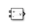
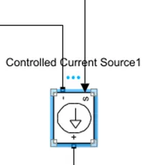
6. Use a Controlled Current Source for battery discharging and connect the load to source. Here, we are using 5.4.
Tip: The current sensor arrow pointing outwards represent discharging of battery.
7. After connecting the above parameters, the circuit will finally look like this.
Calculations:
Nominal battery pack voltage = Nominal cell V*no cells in series
Nominal battery pack voltage = 8.375 * 3 = 25.125
Nominal battery pack current = Nominal cell I*no cells in parallel
Nominal battery pack current = 2.75*2 = 5.50
Results:
SOC, Current and Voltage of battery:
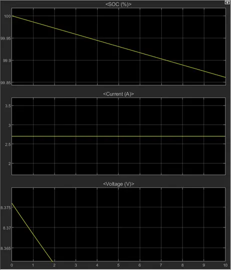
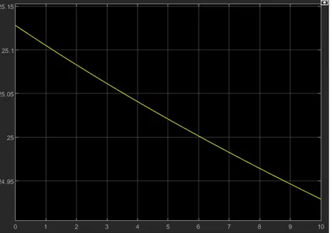
Voltage measurement output: